Marantz Flat Panel Television PD4220V Manuel utilisateur
- Catégorie
- Affichages publics
- Taper
- Manuel utilisateur
Ce manuel convient également à

Model PD4220V User Guide
Plasma Monitor

Introduction to the Plasma Monitor
Marantz’s Plasma Monitor is a seamless blend of cutting-
edge visual technology and sophisticated design. At each inch,
with a 16:9 aspect ratio, the Plasma Monitor certainly makes
a big impression. However, the monitor’s sleek techno-art
lines blend in well with your environment. Marantz Plasma
Monitor’s crisp, vivid image quality will transform data from
any graphic medium from PCs to DVD players- into art.
Marantz has made sure that a host of multimedia resources
can be easily connected and displayed as brilliantly as
intended on the Plasma Monitor.
The features you’ll enjoy include:
• Color Filter and black matrix
• The enhanced display in red uses a two-stage filtering
system.
• Flicker - and warp - free display provides excellent image
geometry even in screen corners
• Not affected by magnetic fields, no color drift or edge
distortion.
• VGA, SVGA, XGA, SXGA, UXGA computer signal
compatibility
• NTSC, PAL, SECAM, composite and S-Video signal
compatibility
• 480P, 1080I, 720P and HDTV signal compatibility
• PCs, VCRs, Laser Disc and DVD player source
compatibility
• AccuBlend scan conversion automatically converts VGA,
SVGA, XGA, SXGA and UXGA signals to the panel’s
native resolution.
• Advanced Mass Area Sampling Progressive Scan method
is employed.
• RGB (3*), Video (3), DVD/HD (2*), Audio input (3),
External Control input (1)
• AccuColor control system provides user selectable on-
screen color temperature settings
• New Drive Technology
• Component video input terminal for DVD, 15.75kHz (Y,
C
B, CR )
• Digital broadcasting source compatibility
• OSM menu-driven on screen control system that makes
image adjustments a snap
• Seven languages (English, German, French, Italian,
Spanish, Swedish, and Chinese)
* You can set the 5BNC input to be used as an RGB or component
input. When the 5BNC input is set for RGB, there are a total of
three RGB inputs; when the 5BNC input is set for component
there are a total of two DVD/HD inputs (see page 24).
Introduction
Contents of the Package
䡺 Plasma monitor
䡺 Power cord
䡺 Remote control with two AAA Batteries
䡺 Manuals
䡺 Safety metal fitting parts*
䡺 Ferrite cores, bands
䡺 Cable clamps
* Contents will differ according to the model.
* These are fittings for fastening the unit to a wall to prevent tipping
due to external shock when using the stand (optional). Fasten the
safety fittings to the holes in the back of the monitor using the
safety fitting mount screws (see page 1).
Options
• Wall mount unit
• Stand

Precautions
Please read this manual carefully before using your plasma
monitor and keep the manual handy for future reference.
CAUTION
RISK OF ELECTRIC SHOCK
DO NOT OPEN
CAUTION:
TO REDUCE THE RISK OF ELECTRIC
SHOCK, DO NOT REMOVE COVER. NO
USER-SERVICEABLE PARTS INSIDE.
REFER SERVICING TO QUALIFIED
SERVICE PERSONNEL.
This symbol warns the user that uninsulated
voltage within the unit may have sufficient
magnitude to cause electric shock.
Therefore, it is dangerous to make any kind
of contact with any part inside of this unit.
This symbol alerts the user that important
literature concerning the operation and
maintenance of this unit has been included.
Therefore, it should be read carefully in
order to avoid any problems.
WARNING
TO PREVENT FIRE OR SHOCK HAZARDS, DO NOT EXPOSE
THIS UNIT TO RAIN OR MOISTURE. ALSO DO NOT USE
THIS UNIT’S POLARIZED PLUG WITH AN EXTENSION CORD
RECEPTACLE OR OTHER OUTLETS, UNLESS THE
PRONGS CAN BE FULLY INSERTED. REFRAIN FROM
OPENING THE CABINET AS THERE ARE HIGH-VOLTAGE
COMPONENTS INSIDE. REFER SERVICING TO QUALIFIED
SERVICE PERSONNEL.
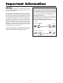
Important Information
Warnings and Safety Precaution
This plasma monitor is designed and
manufactured to provide long, trouble-free service.
No maintenance other than cleaning is required.
Please see the section “Plasma monitor cleaning
procedure” on the next page.
The plasma display panel consists of fine picture
elements (cells) with more than 99.99 percent active
cells. There may be some cells that do not produce
light or remain lit.
For operating safety and to avoid damage to the unit,
read carefully and observe the following instructions.
To avoid shock and fire hazards:
1. Provide adequate space for ventilation to avoid internal
heat build-up. Do not cover rear vents or install the unit
in a closed cabinet or shelves.
If you install the unit in an enclosure, make sure there
is adequate space at the top of the unit to allow hot air
to rise and escape. If the monitor becomes too hot, the
overheat protector will be activated and the monitor will
be turned off. If this happens, turn off the power to the
monitor and unplug the power cord. If the room where
the monitor is installed is particularly hot, move the
monitor to a cooler location, and wait for 60 minutes to
cool the monitor. If the problem persists, contact your
Marantz dealer for service.
2. Do not use this unit’s polarized plug with extension cords
or outlets unless the prongs can be completely inserted.
3. Do not expose the unit to water or moisture.
4. Avoid damage to the power cord, and do not attempt to
modify the power cord.
5. Unplug the power cord during electrical storms or if
the unit will not be used over a long period.
6. Do not open the cabinet which has potentially dangerous
high voltage components inside. If the unit is damaged in
this way the warranty will be void. Moreover, there is a
serious risk of electric shock.
7. Do not attempt to service or repair the unit. The
manufacturer is not liable for any bodily harm or damage
caused if unqualified persons attempt service or open
the back cover. Refer all service to authorized Marantz
Service Centers.

To avoid damage and prolong operating life:
1. Use only with 120V 50/60Hz AC power supply.
Continued operation at line voltages greater than 120 Volts
AC will shorten the life of the unit, and might even cause
a fire hazard.
2. Handle the unit carefully when installing it and do not
drop.
3. Set the unit away from heat, excessive dust, and direct
sunlight.
4. Protect the inside of the unit from liquids and small
metal objects. In case of accident, unplug the power
cord and have it serviced by an authorized Service
Center.
5. Do not hit or scratch the panel surface as this causes
flaws on the surface of the screen.
6. For correct installation and mounting it is strongly
recommended to use a trained, authorized dealer.
7. As is the case with any phosphor-based display (like a
CRT monitor, for example) light output will gradually
decrease over the life of a Plasma Display Panel.
8. To avoid sulfurization it is strongly recommended not to
place the unit in a dressing room in a public bath or hot
spring bath.
Plasma monitor cleaning procedure:
1. Use a soft dry cloth to clean the front panel and bezel
area. Never use solvents such as alcohol or thinner to
clean these surfaces.
2. Clean plasma ventilation areas with a vacuum cleaner
with a soft brush nozzle attachment.
3. To ensure proper ventilation, cleaning of the ventilation
areas must be carried out monthly. More frequent cleaning
may be necessary depending on the environment in which
the plasma monitor is installed.
Recommendations to avoid or minimize phosphor burn-in:
Like all phosphor-based display devices and all other gas
plasma displays, plasma monitors can be susceptible to
phosphor burn under certain circumstances. Certain
operating conditions, such as the continuous display of a
static image over a prolonged period of time, can result in
phosphor burn if proper precautions are not taken. To protect
your investment in this plasma monitor, please adhere to the
following guidelines and recommendations for minimizing
the occurrence of image burn:
* Always enable and use your computer’s screen saver
function during use with a computer input source.
* Display a moving image whenever possible.
* Change the position of the menu display from time to time.
* Always power down the monitor when you are finished
using it.
If the plasma monitor is in long term use or continuous
operation take the following measures to reduce the
likelihood of phosphor burn:
* Lower the Brightness and Contrast levels as much as
possible without impairing image readability.
* Display an image with many colors and color gradations
(i.e. photographic or photo-realistic images).
* Create image content with minimal contrast between light
and dark areas, for example white characters on black
backgrounds. Use complementary or pastel color whenever
possible.
* Avoid displaying images with few colors and distinct,
sharply defined borders between colors.
*
Note:
Burn-in is not covered by the warranty.
Contact Marantz Service Center for other recommended
procedures that will best suit your particular application
needs.

Précautions
Veuillez lire avec attention ce manuel avant d’utiliser le
moniteur à plasma et le conserver accessible pour s’y référer
ultérieurement.
ATTENTION
RISQUE D’ELECTROCUTION
NE PAS OUVRIR
MISE EN GARDE: AFIN DE REDUIRE LES RISQUES
D’ELECTRO-CUTION, NE PAS
DEPOSER LE COUVERCLE, IL N’Y A
AUCUNE PIECE UTILISABLE A
L’INTERIEUR DE CET APPAREIL. NE
CONFIER LES TRAVAUX D’ENTRETIEN
QU’A UN PERSONNEL QUALIFIE.
Ce symbole a pour but de prévenir l’utilisateur
de la présence d’une tension dangereuse, non
isolée se trouvant à l’intérieur de l’appareil.
Elle est d’une intensité suffisante pour
constituer un risque d’électrocution. Eviter le
contact avec les pièces à l’intérieur de cet
appareil.
Ce symbole a pour but de prévenir l’utilisateur
de la présence d’importantes instructions
concernant l’entretien et le fonctionnement de
cet appareil. Par conséquent, elles doivent être
lues attentivement afin d’éviter des problèmes.
AVERTISSEMENT
AFIN DE REDUIRE LES RISQUES D’INCENDIE OU
D’ELECTROCUTION, NE PAS EXPOSER CET APPAREIL
A LA PLUIE OU A L’HUMIDITE. AUSSI, NE PAS UTILISER
LA FICHE POLARISEE AVEC UN PROLONGATEUR OU
UNE AUTRE PRISE DE COURANT SAUF SI CES LAMES
PEUVENT ETRE INSEREES A FOND. NE PAS OUVRIR
LE COFFRET, DES COMPOSANTS HAUTE TENSION SE
TROUVENT A L’INTERIEUR. LAISSER A UN
PERSONNEL QUALIFIE LE SOIN DE REPARER CET
APPAREIL.
Mises en garde et précautions de
sécurité
Ce moniteur à plasma a été conçu et fabriqué pour
une utilisation fiable et durable. Il ne nécessite aucun
entretien en dehors du nettoyage. Voir la section
“Méthode de nettoyage du moniteur à plasma” plus loin.
Le panneau à affichage plasma est constitué de fines
particules d’images (cellules) dont plus de 99,99%sont
actives. Certaines d’entre elles ne produisent pas de
lumière ou restent allumées.
Pour des raisons de sécurité et pour éviter
d’endommager l’appareil, lire attentivement les
instructions suivantes.
Pour éviter les risques d’éléctrocution et d’incendie:
1. Laisser suffisament d’espace autour de l’appareil pour
la ventilation et éviter toute augmentation excessive de
la température interne. Ne pas couvrir les évents ou
l’installer dans un endroit trop exigu.
Si vous installez l’appareil dans un espace clos,
assurezvous qu’il y ait suffisamment d’espace au dessus
pour permettre à l’air chaud de s’élever et de s’évacuer.
Si la température du moniteur devient excessive, la
protection contre les surchauffes entrera en action et
coupera l’alimentation. Dans ce cas, éteindre l’appareil
et débrancher le câble d’alimentation. Si la température
de la pièce dans laquelle se trouve le moniteur est
particulièrement élevée, déplacer celui-ci dans un endroit
plus frais et attendre environ 60 minutes qu’il refroidisse.
Si le problème persiste, prendre contact avec le revendeur
Marantz pour le service après-vente.
2. Ne pas raccorder la prise d’alimentation polarisée de ce
périphérique à une rallonge ou une prise murale si les
fiches ne peuvent pas être complètement insérées.
3. Ne pas exposer à L’eau ou à l’humidité.
4. Eviter d’endommager le cordon d’alimentation, et ne pas
modifier le cordon d’alimentation.
5. Débrancher le câble d’alimentation électrique pendant les
orages ou les longues périodes d’inactivité.
6. Ne pas ouvrir le coffret. Des composants de haute
tension se trouvent à l’intérieur. Si l’appareil est
endommagé de cette manière, la garantie devient
caduque. De plus, il y a risque d’électrocution.
7. Ne pas essayer d’intervenir ou de réparer l’appareil. Le
fabricant décline toute responsabilité en cas de blessure
corporelle ou de dégâts matériels résultant d’une opération
d’entretien quelconque effectuée par des personnes non
qualifiées ou résultant de l’ouverture du couvercle arrière.
Confier toute réparation à un centre de service agréé
Marantz.
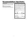
Recommandations importantes

Pour éviter des dommages et prolonger la durée de
service de l’appareil:
1. N’utiliser qu’une source d’alimentation de 120 V 50/
60 Hz CA. Le fait d’utiliser l’appareil en continu à des
tensions de ligne supérieures à 120 Volts CA réduit sa
durée de vie et risque de provoquer un incendie.
2. Manipuler l’appareil avec soin pendant son
déplacement et ne pas le faire tomber.
3. Eloigner l’appareil des endroits chauds, très poussiéreux
et exposés en plein soleil.
4. Eviter que des liquides et des petits objets métalliques
pénètrent à l’intérieur de l’appareil. En cas d’incident de
ce genre, débrancher le câble d’alimentation électrique
et confier le moniteur à un service après-vente agréé.
5. Ne pas frapper ou rayer la surface de la écran plasma,
car des défauts risquent de se produire sur la surface
de la écran plasma.
6. Pour un montage et une installation correcte, il est
fortement recommandé de faire appel à un revendeur
agréé et qualifié.
7. Comme c’est le cas pour tout affichage à base de
phosphore (comme un moniteur CRT, par exemple), la
puissance de lumière baisse graduellement au cours de
la vie du Panneau d’Affichage à Plasma.
8. Pour éviter tout risque de sulfuration, il est fortement
conseillé de ne pas installer l’appareil dans un vestiaire,
un bain public ou un bain de source thermale.
Méthode de nettoyage du moniteur à plasma:
1. Nettoyer le panneau avant et le cadre en procédant à l’aide
d’un chiffon doux et sec. Ne jamais utiliser de solvents
du type alcool ou diluant pour le nettoyage de ces surfaces.
2. Nettoyer les prises d’aération du plasma en procédant à
l’aide d’une brosse à poils doux fixée à un aspirateur.
3. Pour garantir la bonne ventilation du moniteur, nettoyer
les prises d’air tous les mois. Un nettoyage plus fréquent
peut s’avérer nécessaire selon les conditions
environnantes dans lesquelles le moniteur à plasma est
utilisé.
Pour éviter les risques de brûlage du luminophore, les
mesures suivantes sont recommandées:
Comme tous les périphériques d’affichage à base luminophore
et tous les autres affichages gaz plasma, les moniteurs plasma
peuvent être sujets au brûlage du luminophore dans certaines
circonstances. Certaines conditions d’utilisation, telles que
l’affichage continu d’une image statique pour une durée
prolongée, peuvent causer le brûlage du luminophore si
aucune précaution n’est prise. Pour protéger votre
investissement dans ce moniteur à plasma, veuillez suivre
les directives et les conseils suivantes pour minimiser
l’occurence le marquage de l’écran:
• Assurez-vous de mettre en marche et d’utliser
l’économisateur d’écran chaque fois que c’est possible
lorsque vous l’utilisez avec une source d’entrée
d’ordinateur.
• Affichez une image en mouvement aussi souvent que
possible.
• Changer la position de l’affichage de menu de temps à autre.
• Coupez toujours l’alimentation lorsque vous avez terminé
d’utiliser la moniteur.
Si le moniteur est en usage continu ou longue durée, prenez
les mesures suivantes afin d’éviter l’occurence le brûlage
du luminophore:
• Abaissez le niveau de l’image (contraste, luminosité)
autant que possible, sans faire perdre la lisibilité de
l’image.
• Affichez une image avec de nombreuses couleurs et
graduations de couleur (par ex. des images
photographiques ou photo-réalistes).
• Créez un contenu d’image avec un contraste minimal
entre les zones sombres et les zones claires, par exemple,
des caractères blancs sur un fond noir. Utilisez des
couleurs complémentaires ou pastels le plus souvent
possible.
•Évitez d’afficher des images avec peu de couleurs et des
limites nettes et clairement définies entre les couleurs.
*
Remarque:
Le brûlage de l’écran n’est pas couvert
par la garantie.
Contactez Marantz Service Center pour d’autres procédures
recommandées qui conviendront le mieux au besoin de votre
appareil.

How to Attach Options to the Plasma Monitor .... 1
Ventilation Requirements for enclosure mounting .......... 1
How to use the safety metal fittings and the screws for
safety metal fittings ................................................. 1
Part Names and Function .................................. 2
Front View .............................................................. 2
Rear View / Terminal Board ...................................... 3
Remote Control ........................................................ 4
Battery Installation and Replacement ...........................5
Using the wired remote control mode .......................... 6
Operating Range .......................................................... 6
Handling the remote control......................................... 6
Installation ...................................................... 7
Connecting Your PC or Macintosh Computer ............... 8
Connections with Equipment that have a Digital Interface ......
8
Connecting Your Document Camera ........................... 8
Connecting Your VCR or Laser Disc Player.................. 8
Connecting Your DVD Player ..................................... 8
Pin Assignments and Signal Levels
for 15 pin RGB (Analog) ......................................... 9
Pin Configuration and Signal Levels
of the RGB 3 Connector (DVI Connector) ................... 9
Creating a video wall ............................................. 10
Cable Management................................................ 10
Basic Operations ............................................. 11
POWER ................................................................ 11
To turn the unit ON and OFF: .................................... 11
VOLUME .............................................................. 11
To adjust the sound volume:...................................... 11
MUTE ................................................................... 11
To cancel the sound:.................................................. 11
DISPLAY ................................................................ 11
To check the settings: ................................................. 11
DIGITAL ZOOM ..................................................... 11
AUTO ADJUST ...................................................... 11
To adjust the size or quality of the picture automatically
.... 11
OFF TIMER ........................................................... 12
To set the off timer: ................................................... 12
To check the remaining time: ..................................... 12
To cancel the off timer: .............................................. 12
WIDE Operations ............................................. 13
Wide Screen Operation (manual) ........................... 13
When viewing videos or digital video discs .............. 13
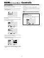
Wide Screen Operation with Computer Signals ......... 14
When “PICTURE SIZE” is set to “OFF” .................. 14
OSM Controls .................................................. 15
Menu Operations ................................................... 15
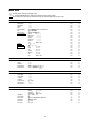
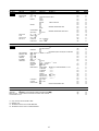
Menu Tree ............................................................. 16
Picture Settings Menu.............................................. 18
Adjusting the picture.................................................. 18
Setting the picture mode according to the brightness
of the room .............................................................. 18
Reducing noise in the picture ..................................... 19
Setting the color temperature ..................................... 19
Adjusting the color to the desired level ...................... 19
Changing the Gamma Curve ...................................... 20
Making the Low Tone adjustments ............................ 20
Adjusting the colors ................................................... 21
Audio Settings Menu .............................................. 21
Adjusting the treble, bass and left/right balance
and audio input select............................................... 21
Setting the allocation of the audio connectors ............ 22
Image Adjust Settings Menu .................................... 22
Adjusting the Position, Size, Fine Picture, Picture Adj
....... 22
Option1 Settings Menu ........................................... 23
Setting the on-screen menu ........................................ 23
Setting the BNC connectors ....................................... 24
Checking the signal being transmitted to RGB1 terminal ....
24
Setting a computer image to the correct RGB
select screen ............................................................. 24
Setting high definition images to the suitable
screen size................................................................ 25
Setting the Input Skip................................................. 25
Resetting to the default values.................................... 26
Option2 Settings Menu ........................................... 26
Setting the power management for computer images ..........
26
POWER/STANDBY indicator ................................... 27
Setting the picture to suit the movie ........................... 27
Reducing burn-in of the screen .................................. 27
Setting the gray level for the sides of the screen ......... 30
Setting the screen size for S1/S2 video input .............. 30
Setting the picture size for RGB input signals ............ 31
Setting the signal and black level for DVI signal........ 31
Option3 Settings Menu ........................................... 32
Using the timer .......................................................... 32
Setting the power on mode........................................ 33
Enabling/disabling the front panel controls ................ 34
Enabling/disabling remote control wireless
transmission ............................................................. 34
Loop Out setting ........................................................ 35
ID number setting ...................................................... 35
Video Wall setting...................................................... 36
Advanced OSM Settings Menu ................................ 39
Setting the menu mode .............................................. 39
Language Settings Menu ......................................... 40
Setting the language for the menus............................. 40
Color System Settings Menu .................................... 40
Setting the video signal format................................... 40
Source Information Menu ........................................ 40
Checking the frequencies, polarities of input signals,
and resolution .......................................................... 40
External Control ............................................. 41
Troubleshooting ............................................. 42
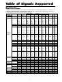
Contents

1
50
mm
(2")
50
mm
(2") 50
mm
(2")
Wall
Wall
50
mm
(2")
50
mm
(2")
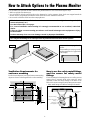
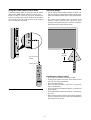
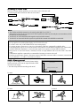
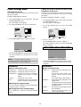
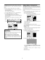
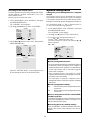
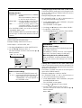
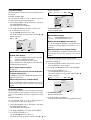
You can attach your optional mounts or stand to the plasma monitor in one of the following two ways:
* While it is upright. (See Drawing A)
* As it is laid down with the screen face down (See Drawing B). Lay the protective sheet, which was wrapped around the
monitor when it was packaged, beneath the screen surface so as not to scratch the screen face.
* Do not touch or hold the screen face when carrying the unit.
• This device cannot be installed on its own. Be sure to use a stand or original mounting unit. (Wall
mount unit, Stand, etc.)
* See the inside of the cover page.
• For correct installation and mounting it is strongly recommended to use a trained, authorized
dealer.
Failure to follow correct mounting procedures could result in damage to the equipment or injury
to the installer.
Product warranty does not cover damage caused by improper installation.
How to Attach Options to the Plasma Monitor
* Use only the mounting kit or stand provided by manufacturer and listed under Options.
Drawing B
Drawing A
Some models are equipped with
handles.
When installing or carrying, use the
handles attached to the upper back
of the display.
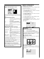
How to use the safety metal fittings
and the screws for safety metal
fittings
These are fittings for fastening the unit to a wall to prevent
tipping due to external shock when using the stand
(optional). Fasten the safety fittings to the holes in the
back of the monitor using the safety fitting mount screws.
* Safety metal fittings will differ according to the model.
Screw hole
Wall
Table Top
Safty metal fittings
Screw for Safty metal
fittings
Metal chain
(Not supplied)
Screw or Hook etc.
(Not supplied)
Ventilation Requirements for
enclosure mounting
To allow heat to disperse, leave space between surrounding
objects as shown on the diagram below when installing.

2
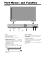
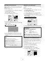
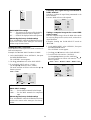
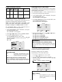
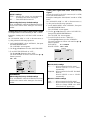
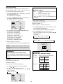
q Power
Turns the monitor’s power on and off.
w Remote sensor window
Receives the signals from the remote control.
e POWER/STANDBY indicator
When the power is on ............................. Lights green.
When the power is in the standby mode ... Lights red.
* POWER/STANDBY letter is printed on model
PD6140 and PD5040 only.
r INPUT SELECT / EXIT
Switches the input, in the following order.
The available inputs depend on the setting of “BNC
INPUT”.
RGB:
COMP.:
Functions as the EXIT buttons in the On-Screen Menu
(OSM) mode.
Front View
Part Names and Function
MENU/ENTER
INPUT SELECT
DOWN UP LEFT/
-
RIGHT/
+
/EXIT
VOLUME
POWER/STANDBY
MENU/ENTER
INPUT SELECT
DOWN UP LEFT/
-
RIGHT/
+
/EXIT
VOLUME
POWER/STANDBY
4
5
6
7
1
3
2
t LEFT/– and RIGHT/+
Enlarges or reduces the image. Functions as the
CURSOR (
/
) buttons in the On-Screen Menu
(OSM) mode.
y VOLUME DOWN and UP
Adjusts the volume. Functions as the CURSOR (▲/
▼) buttons in the On-Screen Menu (OSM) mode.
u MENU/ENTER
Sets the On-Screen Menu (OSM) mode and displays
the main menu.
→ VIDEO1 → VIDEO2 → VIDEO3 → HD/DVD/DTV
RGB/PC3 ← RGB/PC2 ← RGB/PC1←
→VIDEO1 → VIDEO2 → VIDEO3 → HD1/DVD1/DTV1
RGB/PC2 ← RGB/PC1 ← HD2/DVD2/DTV2 ←

3
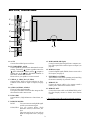
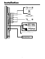
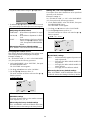
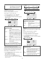
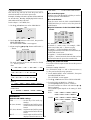
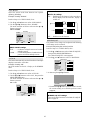
Rear View/ Terminal Board
A AC IN
Connect the included power cord here.
B EXT SPEAKER L and R
Connect speakers (optional) here. Maintain the correct
polarity. Connect the
(positive) speaker wire to the
EXT SPEAKER terminal and the (negative)
speaker wire to the
EXT SPEAKER terminal on
both LEFT and RIGHT channels.
Please refer to your speaker’s owner’s manual.
C VIDEO1, 2, 3 (BNC, RCA, S-Video)
Connect VCR’s, DVD’s or Video Cameras, etc. here.
VIDEO1 can be used for Input or Output (see page
10).
D AUDIO1, AUDIO2, AUDIO3
These are audio input terminals.
The input is selectable. Set which video image to allot
them from the audio menu screen.
E DVD1 / HD1
Connect DVD’s, High Definition or Laser Discs, etc.
here.
F RGB2/ DVD2/ HD2
RGB2: You can connect an analog RGB signal
and the syncronization signal.
DVD2/ HD2: You can connect DVDs, High
Definition sources, Laser Discs, etc.
here.
This input can be set for use with an
RGB or component source. (see page
24)
G RGB1 (mini D-Sub 15pin)
Connect an analog RGB signal from a computer, etc.
here. This input can be used for Input or Output. (see
page 10)
H RGB3
(DVI 24pin)
Connect a digital signal (TMDS) from a source with a
DVI output. (see page 8)
I EXTERNAL CONTROL
This terminal is used when operating and controlling
the monitor externally (by external control).
J REMOTE IN
Connect the remote cable* to the remote control’s
remote jack to obtain wired remote control.
K REMOTE OUT
Connect the remote cable* to the REMOTE IN jack of
the other display monitor to obtain wired remote
control.
* The 1/8 Stereo Mini cable must be purchased separately.
VIDEO
(
IN/OUT
)
VIDEO
1
VIDEO
2
VIDEO
3
AUDIO
1
DVD
1
/ HD
1
R
(
MONO
)
L
Y Cb/Pb Cr/ Pr
RGB
2
/ DVD
2
/ HD
2
RGB
1
R/
VD
G/ B/
HD
(
IN/OUT
)
DVI
(
Digital RGB
)
AUDIO
2
R
(
MONO
)
L
AUDIO
3
R
(
MONO
)
L
Cr/Pr Y Cb/Pb
RGB
3
AB
D
C
E
F
G
H
I
J
K
External Control
IN OUT
REMOTE

4
→ VIDEO1 → VIDEO2 → VIDEO3
RGB/PC DVD/HD
VIDEO
POSITION
/ CONTROL
MENU/ENTER
POINTER
ZOOM
OFF TIMER
EXIT
VOLUME
MUTE
WIDE DISPLAY
MULTI SELECT
AUTO ADJUST
ID SELECT CLEAR
POWER
ON
STANDBY
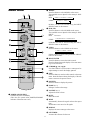
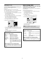
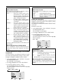
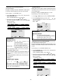
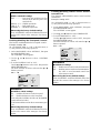
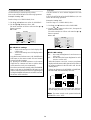
Remote Control
q POWER ON/STANDBY
Switches the power on/standby.
(This does not operate when POWER/STANDBY
indicator of the main unit is off.)
w RGB/PC
Press this button to select RGB/PC as the source.
The available sources depend on the setting of “BNC
INPUT”.
RGB:
COMP. :
RGB/PC can also be selected using the INPUT
SELECT button on the monitor.
e DVD / HD
Press this button to select DVD/HD as the source.
The available sources depend on the setting of “BNC
INPUT”.
RGB:
COMP.:
DVD/HD can also be selected using the INPUT
SELECT button on the monitor.
r VIDEO
Press this button to select VIDEO as the source.
VIDEO can also be selected using the INPUT SELECT
button on the monitor.
t MENU/ENTER
Press this button to access the OSM controls.
Press this button during the display of the main menu
to go to the sub menu.
y CURSOR (▲ / ▼ /
/
)
Use these buttons to select items or settings and to
adjust settings or switch the display patterns.
u EXIT
Press this button to exit the OSM controls in the main
menu. Press this button during the display of the sub
menu to return to the previous menu.
i POINTER
Press this button to display the pointer.
o ZOOM (+ /–)
Enlarges or reduces the image.
!0 VOLUME (+ /–)
Adjusts the audio volume.
!1 MUTE
Mutes the sound.
!2 WIDE
Automatically detects the signal and sets the aspect
ratio.
Wide button is not active for all signals.
!3 DISPLAY
Displays the source settings on the screen.
!4 OFF TIMER
Activates the off timer for the unit.
→ RGB/PC1 → RGB/PC2 → RGB/PC3
→ RGB/PC1 → RGB/PC3
HD/DVD/DTV
→ HD1/DVD1/DTV1 → HD2/DVD2/DTV2

5
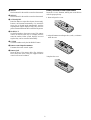
Battery Installation and Replacement
Insert the 2 “AAA” batteries, making sure to set them in
with the proper polarity.
1.Press and open the cover.
2.Align the batteries according to the (+) and (–) indication
inside the case.
3.Replace the cover.
!5 MULTI
Not functional for the models covered in this manual.
!6 SELECT
Not functional for the models covered in this manual.
!7 AUTO ADJUST
Press this button to adjust Fine Picture, Picture ADJ,
Position, and Contrast automatically, or to switch the
screen size to ZOOM mode automatically with the
superimposed caption displayed fully only when the
picture contains dark areas above and below the picture.
!8 ID SELECT
Set the ID number in the remote control. The remote
control can then be used only for a display with the
same ID number. When several displays are used
together they can be controlled individually.
!9 CLEAR
Clears the number set by the ID SELECT button.
@0 Remote control signal transmitter
Transmits the remote control signals.
@1 Remote Jack
Insert the plug of the remote cable (The 1/8 Stereo
Mini cable) here when using the supplied remote
control in the wired condition.

6
POWER/STANDBY
Approx.
7m/23ft
Using the wired remote control mode
Connect the remote cable* to the remote control’s remote
jack and the “REMOTE IN” terminal on the monitor.
When the cable is connected, the mode automatically
switches to wired remote control. When the wired remote
control mode is used, the remote control can be operated
even if no batteries are loaded.
Operating Range
* Use the remote control within a distance of about 7 m/
23ft. from the front of the monitor’s remote control sensor
and at horizontal and vertical angles of up to approximately
30°.
* The remote control operation may not function if the
monitor’s remote control sensor is exposed to direct
sunlight or strong artificial light, or if there is an obstacle
between the sensor and the remote control.
Handling the remote control
• Do not drop or mishandle the remote control.
• Do not get the remote control wet. If the remote control
gets wet, wipe it dry immediately.
• Avoid heat and humidity.
• When not using the remote control for a long period,
remove the batteries.
• Do not use new and old batteries together, or use different
types together.
• Do not take apart the batteries, heat them, or throw them
into a fire.
• When using the remote control in the wireless condition,
be sure to unplug the remote cable from the REMOTE
IN terminal on the monitor.
RGB
2
/
DVD
2
/
HD
2
RGB
1
R/
VD
G/ B/
HD
(
IN /OUT
)
DVI
(
Digital RGB
)
AUDIO
2
R
(
MONO
)
L
AUDIO
3
R
(
MONO
)
L
Cr/Pr Y Cb/Pb
RGB
3
External Control
IN OUT
REMOTE
External Control
IN OUT
REMOTE
Remote Control
Cable*
To Remote Jack
* The 1/8 Stereo Mini cable must be purchased separately.

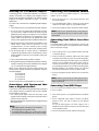
7
Installation
VIDEO
(
IN/OUT
)
VIDEO
1
VIDEO
2
VIDEO
3
AUDIO
1
DVD
1
/ HD
1
R
(
MONO
)
L
Y Cb/Pb Cr/Pr
RGB
2
/ DVD
2
/ HD
2
RGB
1
R/
VD
G/ B/
HD
(
IN/ OUT
)
DVI
(
Digital RGB
)
AUDIO
2
R
(
MONO
)
L
AUDIO
3
R
(
MONO
)
L
Cr/Pr Y Cb/Pb
RGB
3
External Control
IN OUT
REMOTE
VCR or Laser Disc Player
Document Camera
VIDEO 1-3
DVD Player
IBM VGA or
Compatibles
To Mini D-Sub 15 pin connector on the plasma monitor
To video inputs on
the plasma monitor
Monitor adapter for
Macintosh
Macintosh or Compatibles
(Desk top type)
Personal computer with a
digital signal output

8
Connecting Your PC or Macintosh Computer
Connecting your PC or Macintosh computer to your plasma
monitor will enable you to display your computer’s screen
image for an impressive presentation. The plasma monitor
supports the signals described on page 7 of Model
Information.
To connect a PC, Macintosh or compatible graphics adapter,
simply:
1. Turn off the power to your plasma monitor and computer.
2. If your PC does not support SXGA/XGA/SVGA/VGA
you will need to install an SXGA/XGA/SVGA/VGA
graphics board. Consult your computer’s owner’s manual
for your SXGA/XGA/SVGA/VGA configuration. If you
need to install a new board, see the manual that comes
with your new graphics board for installation instructions.
3. This plasma monitor provides signal compatibility up to
VESA 16001200 (UXGA). However, it is not
recommended to use this resolution due to image
readability on the monitor’s native pixel resolution panel.
4. Use the signal cable to connect your PC or Macintosh
computer to the plasma monitor. For Macintosh, use the
monitor adapter to connect to your computer’s video port,
if necessary.
5. Turn on the plasma monitor and the computer.
6. If the plasma monitor goes blank after a period of inactivity,
it may be caused by a screen saver installed on the computer
you’ve connected to the plasma monitor.
When using a Macintosh with the plasma monitor, the
following four display standards are supported using the
Macintosh adapter :
13" fixed mode
16" fixed mode
19" fixed mode
21" fixed mode
The 19" fixed mode is recommended for your monitor.
Connections with Equipment that
have a Digital Interface
Connections can be made with equipment that is equipped
with a digital interface compliant with the DVI (Digital
Visual Interface) standard.
* Use a DVI 24-pin signal cable and the ferrite cores
(supplied) when making connections to the RGB3 (DVI)
connector of the main unit.
Note that the RGB3 (DVI) terminal does not support analog
RGB input source.
Note:
1. Input TMDS signals conforming to DVI standards.
The TMDS input corresponds to 1 link.
2. To maintain display quality, use a cable with a quality
prescribed by DVI standards that is within 5 meters in length.
Connecting Your Document Camera
You can connect your plasma monitor to a document
camera. To do so, simply:
1. Turn off the power to your plasma monitor and
document camera.
2. Use a standard video cable to connect your document
camera to the Video input on your plasma monitor.
3. Turn on the plasma monitor and the document camera.
Note:
Refer to your document camera owner’s manual
for more information about your camera’s video output
requirements.
Connecting Your VCR or Laser Disc
Player
Use common RCA cables (not provided) to connect your
VCR or laser disc player to your plasma monitor. To make
these connections, simply:
1. Turn off the power to your plasma monitor and VCR
or laser disc player.
2. Connect one end of your RCA cable to the video output
connector on the back of your VCR or laser disc player,
connect the other end to the Video input on your plasma
monitor. Use standard RCA audio patch cords to
connect the audio from your VCR or laser disc player
to your plasma monitor (if your VCR or laser disc player
has this capability). Be careful to keep your right and
left channel connections correct for stereo sound.
3. Turn on the plasma monitor and the VCR or laser disc
player.
Note:
Refer to your VCR or laser disc player owner’s
manual for more information about your equipment’s video
output requirements.
Connecting Your DVD Player
You can connect your plasma monitor to a DVD player.
To do so, simply:
1. Turn off the power to your plasma monitor and DVD
player.
2. Use a component video cable to connect your DVD
player to the Y, Cb, and Cr inputs on your plasma
monitor.
Or use the DVD-player’s S-Video output. Use a
standard S-Video cable to connect to the S-Video input
on the plasma monitor.
3. Turn on the plasma monitor and the DVD player.

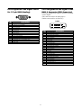
9
5 4 3 2 1
15 14 13 12 11
10 9 8 7 6
Pin Assignments and Signal Levels
for 15 pin RGB (Analog)
Pin Configuration and Signal of the
RGB 3 Connector (DVI Connector)
The unit is equipped with a type of connector commonly
used for digital.
(This cannot be used for an analog input.)
(TMDS can be used for one link only.)
Signal (Analog)
Red
Green or sync-on-green
Blue
No connection
Ground
Red ground
Green ground
Blue ground
No connection
Sync signal ground
No connection
Bi-directional DATA (SDA)
Horizontal sync or Composite sync
Vertical sync
Data clock
Pin No.
1
2
3
4
5
6
7
8
9
10
11
12
13
14
15
12345678
910111213141516
20191817 21 22 23 24
RGB 3
Pin No.
1
2
3
4
5
6
7
8
9
10
11
12
13
14
15
16
17
18
19
20
21
22
23
24
Signal (Digital)
T.M.D.S Data 2 -
T.M.D.S Data 2 +
T.M.D.S Data 2 Shield
No connection
No connection
DDC Clock
DDC Data
No connection
T.M.D.S Data 1 -
T.M.D.S Data 1 +
T.M.D.S Data 1 Shield
No connection
No connection
+5V Power
Ground
Hot Plug Detect
T.M.D.S Data 0 -
T.M.D.S Data 0 +
T.M.D.S Data 0 Shield
No connection
No connection
T.M.D.S Clock Shield
T.M.D.S Clock +
T.M.D.S Clock -

10
Note:
1. The VIDEO1 and RGB1 terminals can be used for either INPUT or OUTPUT.
When LOOP OUT is ON, do not connect an OUTPUT signal from another unit, that will place an extraordinary load on
the other unit and may damage it.
2. LOOP OUT can not be turned ON while signals are input to RGB1 terminal.
3. LOOP OUT can be turned ON while signals are input to RGB1 terminal if the POWER is switched ON.
Information
• To loop signals out to another plasma display, set the LOOP OUT to ON.
• To create a video wall, set the VIDEO WALL menu items properly.
• To connect monitors, please use a 1~2m (3.3~6.6 feet) BNC cable (any commercially available cable).
• If the image quality is poor, do not use the monitor’s out terminal. Use a distribution amplifier (any commercially
available distribution amplifier) to connect the split signals to the respective monitor INPUT terminals.
• Being used as a video wall function, maximaly 4-screen is rough-standard with lower than 1024768, 60Hz
signal.
• A distribution amplifier is particularly recommended when using a 9-screen video wall.
• From the second monitor onward, connections require a BNC-RCA conversion cable or connector, a mini D-Sub
15 pin cable-BNC (5) cable or a conversion connector.
Creating a video wall
With buit-in matrix display capability, you can create a 2×2 or 3×3 video wall.
• Connect signal cables and remote cables as shown below.
Video signal RGB/DVD/HD signal
VIDEO
(
IN/OUT
)
VIDEO
1
VIDEO
2
VIDEO
3
AUDIO
1
DVD
1
R
(
MONO
)
L
Y
IN OUT
REMOTE
BNC connector
RCA phono plug
OUT
VIDEO Signal
IN
IN
OUT
Remote
control
VIDEO Signal
Remote
control
RGB
2
/
DVD
2
/
HD
2
RGB
1
R/
VD
G/ B/
HD
(
IN /OUT
)
Cr/Pr Y Cb/ Pb
IN OUT
REMOTE
BNC connector
RGB signal/
DVD/HD signal
IN
OUT
IN
OUT
Remote
control
RGB signal/
DVD/HD signal
Remote
control
Cable Management
Using the cable clamps provided with the plasma display,
bundle at the back of the unit the signal and audio cables
connected to the display.
* The cable clamp will differ according to the model.
Back of the unit
mounting hooks/mounting holes
clamp
mounting hook
cables
To attach To detach
To attach To detach
clamp
mounting hole
cables
1. 2.
1. 2.

11
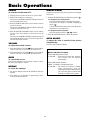
Basic Operations
POWER
To turn the unit ON and OFF:
1. Plug the power cord into an active AC power outlet.
2. Press the Power button (on the unit).
The monitor’s POWER/STANDBY indicator turns red
and the standby mode is set.
3. Press the POWER ON button (on the remote control)
to turn on the unit.
The monitor’s POWER/STANDBY indicator will light
up (green) when the unit is on.
4. Press the POWER STANDBY button (on the remote
control) or the Power button (on the unit) to turn off
the unit.
The monitor’s POWER/STANDBY indicator turns red
and the standby mode is set (only when turning off the
unit with the remote control).
VOLUME
To adjust the sound volume:
1. Press and hold the VOLUME button (on the remote
control or the unit) to increase to the desired level.
2. Press and hold the VOLUME
button (on the remote
control or the unit) to decrease to the desired level.
MUTE
To cancel the sound:
Press the MUTE button on the remote control to cancel
the sound; press again to restore.
DISPLAY
To check the settings:
1. The screen changes each time the DISPLAY button is
pressed.
2. If the button is not pressed for approximately three
seconds, the menu turns off.
DIGITAL ZOOM
Digital zoom specifies the picture position and enlarges
the picture.
1. Press the POINTER button to display the pointer. (
)
To change the size of the picture:
Press the ZOOM+ button and enlarge the picture.
The pointer will change to resemble a magnifying
glass. (
)
A press of the ZOOM- button will reduce the picture
and return it to its original size.
To change the picture position:
Select the position with the ▲▼
buttons.
2. Press the POINTER button to delete the pointer.
AUTO ADJUST
To adjust the size or quality of the picture
automatically:
Press the AUTO ADJUST button.
Information
AUTO ADJUST ON setting
When RGB (still picture) input
is selected......Fine Picture, Picture ADJ, Position,
and Contrast will be adjusted
automatically.
When RGB (motion picture),
VIDEO, or Y/Pb/Pr (component) input
is selected......The screen size switches to ZOOM
mode automatically with the
superimposed caption displayed fully
only when the picture contains dark
areas above and below the picture.

12
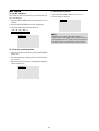
OFF TIMER
To set the off timer:
The off timer can be set to turn the power off after 30, 60,
90 or 120 minutes.
1. Press the OFF TIMER button to start the timer at 30
minutes.
2. Press the OFF TIMER button to the desired time.
3. The timer starts when the menu turns off.
→ 30 → 60 → 90 → 120 → 0
OFF TIMER 30
To check the remaining time:
1. Once the off timer has been set, press the OFF TIMER
button once.
2. The remaining time is displayed, then turns off after a
few seconds.
3. When five minutes remain the remaining time appears
until it reaches zero.
OFF TIMER 28
To cancel the off timer:
1. Press the OFF TIMER button twice in a row.
2. The off timer is canceled.
OFF TIMER 0
Note:
After the power is turned off with the off timer ...
A slight current is still supplied to the monitor. When you
are leaving the room or do not plan to use the system for a
long period of time, turn off the power of the monitor.

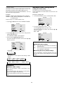
13
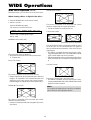
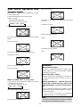
Wide Screen Operation
(manual)
With this function, you can select one of six screen sizes.
When viewing videos or digital video discs
1. Press the WIDE button on the remote control.
2. Within 3 seconds ...
Press the WIDE button again.
The screen size switches as follows:
→ NORMAL → FULL → STADIUM → ZOOM → 2.35:1 → 14:9
When a 720P or 1080I signal is input:
FULL ↔ 2.35:1
NORMAL size screen (4:3)
The normal size screen is displayed.
* The picture has the same size as video pictures with a
4 : 3 aspect ratio.
FULL size screen
The image is expanded in the horizontal direction.
* Images compressed in the horizontal direction (“squeezed
images”) are expanded in the horizontal direction and
displayed on the entire screen with correct linearity.
(Normal images are expanded in the horizontal direction.)
STADIUM size screen
The picture is expanded in the horizontal and vertical
directions at different ratios.
* Use this for watching normal video programs (4:3) with a
wide screen.
ZOOM size screen
The picture is expanded in the horizontal and vertical
direction, maintaining the original proportions.
* Use this for theater size (wide) movies, etc.
2.35:1 size screen
The squeezed film image is expanded to fulfill the entire
screen at a ratio of 2.35:1. Black bands do not appear at
the top and bottom but information is lost on the left and
right margins.
• This feature is available when the input signal is video,
component (480I, 480P, 576I, 576P, 720P, 1080I) or RGB
(525P or 625P signal from a scan converter).
* If black bands appear on the top and bottom in the full size
screen, select the 2.35:1 size screen to avoid phosphor burn-
in.
14:9 size screen
The image is displayed at a 14:9 aspect ratio.
* This feature is available when the input signal is video,
component (480I, 480P, 576I, 576P) or RGB (525P or 625P
signal from a scan converter).
Note:
Do not allow the displayed in 4:3 mode for an extended
period. This can cause a phosphor burn-in.
WIDE Operations
Information is lost on both sides.
Original image
La page est en cours de chargement...
La page est en cours de chargement...
La page est en cours de chargement...
La page est en cours de chargement...
La page est en cours de chargement...
La page est en cours de chargement...
La page est en cours de chargement...
La page est en cours de chargement...
La page est en cours de chargement...
La page est en cours de chargement...
La page est en cours de chargement...
La page est en cours de chargement...
La page est en cours de chargement...
La page est en cours de chargement...
La page est en cours de chargement...
La page est en cours de chargement...
La page est en cours de chargement...
La page est en cours de chargement...
La page est en cours de chargement...
La page est en cours de chargement...
La page est en cours de chargement...
La page est en cours de chargement...
La page est en cours de chargement...
La page est en cours de chargement...
La page est en cours de chargement...
La page est en cours de chargement...
La page est en cours de chargement...
La page est en cours de chargement...
La page est en cours de chargement...
La page est en cours de chargement...
La page est en cours de chargement...
La page est en cours de chargement...
La page est en cours de chargement...
La page est en cours de chargement...
La page est en cours de chargement...
La page est en cours de chargement...
La page est en cours de chargement...
La page est en cours de chargement...
La page est en cours de chargement...
La page est en cours de chargement...
-
 1
1
-
 2
2
-
 3
3
-
 4
4
-
 5
5
-
 6
6
-
 7
7
-
 8
8
-
 9
9
-
 10
10
-
 11
11
-
 12
12
-
 13
13
-
 14
14
-
 15
15
-
 16
16
-
 17
17
-
 18
18
-
 19
19
-
 20
20
-
 21
21
-
 22
22
-
 23
23
-
 24
24
-
 25
25
-
 26
26
-
 27
27
-
 28
28
-
 29
29
-
 30
30
-
 31
31
-
 32
32
-
 33
33
-
 34
34
-
 35
35
-
 36
36
-
 37
37
-
 38
38
-
 39
39
-
 40
40
-
 41
41
-
 42
42
-
 43
43
-
 44
44
-
 45
45
-
 46
46
-
 47
47
-
 48
48
-
 49
49
-
 50
50
-
 51
51
-
 52
52
-
 53
53
-
 54
54
-
 55
55
-
 56
56
-
 57
57
-
 58
58
-
 59
59
-
 60
60


Marantz Flat Panel Television PD4220V Manuel utilisateur
- Catégorie
- Affichages publics
- Taper
- Manuel utilisateur
- Ce manuel convient également à
dans d''autres langues
Documents connexes
Autres documents
-
NEC plasmasync 60xm5, px-60xm5a Manuel utilisateur
-
Pioneer PDP-6100HD Manuel utilisateur
-
-
Pioneer Flat Panel Television PDP-42MVE1 Manuel utilisateur
-
Integra Computer Monitor PLA-50V1 Manuel utilisateur
-
-
NEC PX-50XM5A Manuel utilisateur
-
-
-