Garland 36ER33-88 Owner Instruction Manual
- Catégorie
- Cuisinières
- Taper
- Owner Instruction Manual

Part # 4515576 Rev 2 (01/15/16)
Master Series
Infra-Red & Ceramic Broilers
Installation, Operation and Maintenance Manual
Original Instructions
models
M60XR
M60XRC
M60XS
M60XT
M100XR
M100XRC
M100XS
M100XT
M110XM

Part # 4515576 Rev 2 (01/15/16)Page 2
IMPORTANT INFORMATION
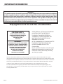
WARNING:
This product contains chemicals known to the state of California to cause cancer and/or birth defects
or other reproductive harm. Installation and servicing of this product could expose you to airborne
particles of glass wool/ceramic fibers. Inhalation of airborne particles of glass wool/ceramic fibers
is known to the state of California to cause cancer. Operation of this product could expose you to
carbon monoxide if not adjusted properly. Inhalation of carbon monoxide is known to the state of
California to cause birth defects or other reproductive harm.
Keep appliance area free and clear of combustibles.
Users are cautioned that maintenance and repairs must be performed by a Garland authorized service agent
using genuine Garland replacement parts. Garland will have no obligation with respect to any product that has been
improperly installed, adjusted, operated or not maintained in accordance with national and local codes or installation
instructions provided with the product, or any product that has its serial number defaced, obliterated or removed,
or which has been modified or repaired using unauthorized parts or by unauthorized service agents.
For a list of authorized service agents, please refer to the Garland web site at http://www.garland-group.com.
The information contained herein, (including design and parts specifications), may be superseded and is subject
to change without notice.
FOR YOUR SAFETY:
DO NOT STORE OR USE GASOLINE
OR OTHER FLAMMABLE VAPORS OR
LIQUIDS IN THE VICINITY OF
THIS OR ANY OTHER
APPLIANCE
WARNING:
IMPROPER INSTALLATION, ADJUSTMENT,
ALTERATION, SERVICE OR MAINTENANCE
CAN CAUSE PROPERTY DAMAGE, INJURY,
OR DEATH. READ THE INSTALLATION,
OPERATING AND MAINTENANCE
INSTRUCTIONS THOROUGHLY
BEFORE INSTALLING OR
SERVICING THIS EQUIPMENT
PLEASE READ ALL SECTIONS OF THIS MANUAL
AND RETAIN FOR FUTURE REFERENCE.
THIS PRODUCT HAS BEEN CERTIFIED AS
COMMERCIAL COOKING EQUIPMENT AND
MUST BE INSTALLED BY PROFESSIONAL
PERSONNEL AS SPECIFIED.
IN THE COMMONWEALTH OF MASSACHUSETTS
THIS PRODUCT MUST BE INSTALLED BY A
LICENSED PLUMBER OR GAS FITTER.
For Your Safety:
Post in a prominent location, instructions to be
followed in the event the user smells gas. This
information shall be obtained by consulting
your local gas supplier.

Part # 4515576 Rev 2 (01/15/16) Page 3
TABLE OF CONTENTS
IMPORTANT INFORMATION. . . . . . . . . . . . . . . . . . . . . . . . . . . . . . . . . . . . . . . . . . 2
SPECIFICATIONS . . . . . . . . . . . . . . . . . . . . . . . . . . . . . . . . . . . . . . . . . . . . . . . . . . . . 4
Technical Speci cations . . . . . . . . . . . . . . . . . . . . . . . . . . . . . . . . . . . . . . . . . . . . . . . . . . . . . . . . . .4
Electrical Supply . . . . . . . . . . . . . . . . . . . . . . . . . . . . . . . . . . . . . . . . . . . . . . . . . . . . . . . . . . . . . . . . .4
Individual Burner Input Ratings . . . . . . . . . . . . . . . . . . . . . . . . . . . . . . . . . . . . . . . . . . . . . . . . . . .4
Model Designations . . . . . . . . . . . . . . . . . . . . . . . . . . . . . . . . . . . . . . . . . . . . . . . . . . . . . . . . . . . . . .4
Clearances . . . . . . . . . . . . . . . . . . . . . . . . . . . . . . . . . . . . . . . . . . . . . . . . . . . . . . . . . . . . . . . . . . . . . . .4
GENERAL INFORMATION . . . . . . . . . . . . . . . . . . . . . . . . . . . . . . . . . . . . . . . . . . . . 5
STATUTORY REGULATIONS . . . . . . . . . . . . . . . . . . . . . . . . . . . . . . . . . . . . . . . . . . 5
INSTALLATION . . . . . . . . . . . . . . . . . . . . . . . . . . . . . . . . . . . . . . . . . . . . . . . . . . . . . . 6
Siting . . . . . . . . . . . . . . . . . . . . . . . . . . . . . . . . . . . . . . . . . . . . . . . . . . . . . . . . . . . . . . . . . . . . . . . . . . . .6
Ventilation Air . . . . . . . . . . . . . . . . . . . . . . . . . . . . . . . . . . . . . . . . . . . . . . . . . . . . . . . . . . . . . . . . . . .6
Gas Connection . . . . . . . . . . . . . . . . . . . . . . . . . . . . . . . . . . . . . . . . . . . . . . . . . . . . . . . . . . . . . . . . . .6
Electrical Connection . . . . . . . . . . . . . . . . . . . . . . . . . . . . . . . . . . . . . . . . . . . . . . . . . . . . . . . . . . . .6
Installation Notices . . . . . . . . . . . . . . . . . . . . . . . . . . . . . . . . . . . . . . . . . . . . . . . . . . . . . . . . . . . . . . .6
Installing Ceramic Radiants (model M60XR) . . . . . . . . . . . . . . . . . . . . . . . . . . . . . . . . . . . . . . .7
Appliances Equipped With Casters . . . . . . . . . . . . . . . . . . . . . . . . . . . . . . . . . . . . . . . . . . . . . . . .7
Appliances Equipped With Legs . . . . . . . . . . . . . . . . . . . . . . . . . . . . . . . . . . . . . . . . . . . . . . . . . .7
Testing & Adjustment . . . . . . . . . . . . . . . . . . . . . . . . . . . . . . . . . . . . . . . . . . . . . . . . . . . . . . . . . . . .7
FDO Heavy Duty Oven control . . . . . . . . . . . . . . . . . . . . . . . . . . . . . . . . . . . . . . . . . . . . . . . . . . . .8
OPERATION. . . . . . . . . . . . . . . . . . . . . . . . . . . . . . . . . . . . . . . . . . . . . . . . . . . . . . . . . 9
Broiler Section . . . . . . . . . . . . . . . . . . . . . . . . . . . . . . . . . . . . . . . . . . . . . . . . . . . . . . . . . . . . . . . . . . .9
Cast Iron Burner With Ceramic Tile - M60X . . . . . . . . . . . . . . . . . . . . . . . . . . . . . . . . . . . . . 9
Infra-Red Burners -M100XM, M110XM . . . . . . . . . . . . . . . . . . . . . . . . . . . . . . . . . . . . . . . . . 9
Ovens . . . . . . . . . . . . . . . . . . . . . . . . . . . . . . . . . . . . . . . . . . . . . . . . . . . . . . . . . . . . . . . . . . . . . . . . . .10
Standard Ovens . . . . . . . . . . . . . . . . . . . . . . . . . . . . . . . . . . . . . . . . . . . . . . . . . . . . . . . . . . . . . 10
Convection Ovens (RC) . . . . . . . . . . . . . . . . . . . . . . . . . . . . . . . . . . . . . . . . . . . . . . . . . . . . . . 10
PRODUCT APPLICATION . . . . . . . . . . . . . . . . . . . . . . . . . . . . . . . . . . . . . . . . . . . 11
Broiler . . . . . . . . . . . . . . . . . . . . . . . . . . . . . . . . . . . . . . . . . . . . . . . . . . . . . . . . . . . . . . . . . . . . . . . . . .11
Convection Ovens . . . . . . . . . . . . . . . . . . . . . . . . . . . . . . . . . . . . . . . . . . . . . . . . . . . . . . . . . . . . . .11
CARE & CLEANING . . . . . . . . . . . . . . . . . . . . . . . . . . . . . . . . . . . . . . . . . . . . . . . . . 12
Stainless Steel . . . . . . . . . . . . . . . . . . . . . . . . . . . . . . . . . . . . . . . . . . . . . . . . . . . . . . . . . . . . . . . . . .12
Oven Interior (Porcelain Enamel) . . . . . . . . . . . . . . . . . . . . . . . . . . . . . . . . . . . . . . . . . . . . . . . . .12
Broiler Section . . . . . . . . . . . . . . . . . . . . . . . . . . . . . . . . . . . . . . . . . . . . . . . . . . . . . . . . . . . . . . . . . .12
General Cleaning. . . . . . . . . . . . . . . . . . . . . . . . . . . . . . . . . . . . . . . . . . . . . . . . . . . . . . . . . . . . 12
M110XM . . . . . . . . . . . . . . . . . . . . . . . . . . . . . . . . . . . . . . . . . . . . . . . . . . . . . . . . . . . . . . . . . . . . 13
M100X (R/RC/S/TM). . . . . . . . . . . . . . . . . . . . . . . . . . . . . . . . . . . . . . . . . . . . . . . . . . . . . . . . . . 13
Instructions For Removal Of Grid Rack &
Grid Rack Frame. . . . . . . . . . . . . . . . . . . . . . . . . . . . . . . . . . . . . . . . . . . . . . . . . . . . . . . . . . . . . 13
WIRING DIAGRAM . . . . . . . . . . . . . . . . . . . . . . . . . . . . . . . . . . . . . . . . . . . . . . . . . 14

Part # 4515576 Rev 2 (01/15/16)Page 4
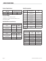
SPECIFICATIONS
Technical Speci cations
MINIMUM SUPPLY
PRESSURE
MANIFOLD
OPERATING PRESSURE
Natural Gas: 7” w.c. Natural Gas: 6” w.c.
Propane: 11” w.c. Propane: 10” w.c.
Electrical Supply
120V 60Hz, 1A – Infra-Red Burner Models.
120V 60Hz, 4.4A - Models with Infra-Red Burners and a
Convection Oven Base.
Individual Burner Input Ratings
Natural Gas
Burner
Input BTU/Hr
per Section
Ori ce Size
DMS
Cast Iron Burner With
Ceramic Tile
80,000 # 35
Infra-Red 70,000 # 50
Oven 40,000 # 33
Propane
Burner
Input BTU/Hr
per Section
Ori ce Size
DMS
Cast Iron Burner With
Ceramic Tile
80,000 # 48
Infra-Red 70,000 # 56
Oven 35,000 # 50
Model Designations
Model
Number
Broiler Burner Base
M60XR Cast Iron Burner With
Ceramic Tile
Standard Oven
M60XRC Cast Iron Burner With
Ceramic Tile
Convection Oven
M60XS Cast Iron Burner With
Ceramic Tile
Storage
M60XT Cast Iron Burner With
Ceramic Tile
Counter Top or
Modular Stand
M100XR Infra-Red Standard Oven
M100XRC Infra-Red Convection Oven
M100XS Infra-Red Storage
M100XT Infra-Red Counter Top or
Modular Stand
M110XM Infra-Red —
Clearances
INSTALLATION CLEARANCES
Model Number Sides Rear
M60XR 6” (152mm) 6” (152mm)
M60XRC 6” (152mm) 6” (152mm)
M60XS 6” (152mm) 6” (152mm)
M60XT 6” (152mm) 6” (152mm)
M100XR 6” (152mm) 6” (152mm)
M100XRC 6” (152mm) 6” (152mm)
M100XS 6” (152mm) 6” (152mm)
M100XT 6” (152mm) 6” (152mm)
M110XM 6” (152mm) 6” (152mm)

Part # 4515576 Rev 2 (01/15/16) Page 5
GENERAL INFORMATION
1. Check crate for possible damage sustained during transit.
Carefully remove unit from crate and again check for
damage. Any damage to the appliance must be reported
to the carrier immediately.
2. The wires for retaining the burners and other packing
material must be removed from units. Any protective
material covering stainless steel parts must also be
removed.
3. All equipment is shipped from the factory with legs
tted, unless otherwise speci ed. Where the range is to
be mounted on a dais or cove base, it is shipped without
legs. Legs must be tted to the oven where it is installed
on a combustible oor.
4. The type of gas and supply pressure that the equipment
was set-up for at the factory is noted on the data plate
and on the packaging. This type of gas supply must be
used.
5. Garland/U.S. Range products are not approved or
authorized for home or residential use, but are intended
for commercial applications only. Garland / U.S. Range
will not provide service, warranty, maintenance
or support of any kind other than in commercial
applications.
6. Do not remove permanently a xed labels, warnings or
data plates from the appliance, for this may invalidate the
manufacturer’s warranty.
STATUTORY REGULATIONS
The installation of this appliance must be carried out by
a competent person and in accordance with the relevant
regulations, codes of practice and the related publications of
the country and destination.
The installation must conform to the National Fuel Gas Code
ANSI Z223.1-latest edition, NFPA No. 54 – latest edition and
National Electrical Code ANSI/NFPA 70-latest edition and/or
local code to assure safe and e cient operation. In Canada,
the installation must comply with CSA B149.1 and local
codes where applicable.
In Canada, electrical connections must comply with
applicable sections of the Canadian Electrical Code, C22.1 -
latest edition.

Part # 4515576 Rev 2 (01/15/16)Page 6
INSTALLATION
Siting
The oor on which the appliance is to be sited must be
capable of adequately supporting the weight of the
appliance and any ancillary equipment.
Units with ovens must be tted with legs if installed on a
combustible oor.
Ventilation Air
The following notes are intended to give general guidance.
For detailed recommendations, refer to the applicable
code(s) in the country of destination.
Proper ventilation is highly essential for optimum
performance. The ideal method of ventilating open-top
equipment is the use of a properly designed canopy which
should extend six inches (152mm), beyond all sides of the
appliance(s) and six feet, six inches (1981mm) above the
oor.
A strong exhaust will create a vacuum in the room. For an
exhaust vent to work properly, replacement air must enter
the room. The amount of air that enters must be equal to the
amount exhausted.
All gas burners and pilots need su cient air to operate. Large
objects should not be placed in front of the appliance(s) that
would obstruct the ow of air into the front.
Gas Connection
The local gas authority should be consulted at the
installation planning stage in order to establish the
availability of an adequate supply of gas and to ensure
that the meter is adequate for the required ow rate. The
pipe work from the meter to the appliances must be of an
appropriate size.
All xed (non-mobile) appliances MUST be tted with a
manual gas-cock upstream of the appliance to provide a
means of isolation for servicing or cleaning purposes. A
union or similar means of disconnection must be provided
between the gas-cock and the appliance.
A manually operable valve must be tted to the gas supply
to the kitchen to enable it to be isolated in an emergency.
Wherever practical, this shall be located either outside the
kitchen or near to an exit in a readily accessible position.
Where it is not practical to do this, an automatic isolation
valve system shall be tted which can be operated from a
readily accessible position near to the exit.
At locations where the manual isolation valve is tted or
the automatic system can be reset, a notice MUST be tted
stating:
“ALL DOWNSTREAM BURNER AND PILOT VALVES MUST
BE TURNED OFF PRIOR TO ATTEMPTING TO RESTORE THE
SUPPLY. AFTER EXTENDED SHUT OFF, PURGE BEFORE
RESTORING GAS SUPPLY.”
Electrical Connection
(Models with Infra-Red Burners and/or Convection Oven
Bases)
IMPORTANT – This appliance must be electrically grounded
in accordance with local codes.
Installation Notices
Before assembly and connection check gas supply.
A. The type of gas for which the unit is equipped is stamped
on the data plate located behind the lower front panel.
Connect a unit stamped “NAT” only to natural gas;
connect one stamped “PRO” only to propane gas.
B. If it is a new installation have the gas authorities check
the meter size and piping to assure that the unit is
supplied with the necessary amount of gas pressure
required for operation.
C. If it is additional or replacement equipment have the
gas authorities check the pressure to make certain that
existing meter and piping will supply fuel to the unit with
no more than 1/2” water column pressure drop.
D. Legs must be tted to the oven where it is installed on a
combustible oor.
E. When installed without legs on a non-combustible curb
or plateform, the front of the unit should extend at least 3
inches or 76 mm such that the air vent is not blocked.
NOTE: When checking gas pressure be sure that all other
equipment on the same gas line is on.
The appliance and its individual shut-o valve must be
disconnected from the gas supply piping system during any
pressure testing of that system with pressures in excess of
1/2 PSIG (3.45kPa).
Adequate clearance must be provided for servicing and
proper operation.
THIS APPLIANCE IS NOT RECOMMENDED FOR RESIDENTIAL
INSTALLATION.

Part # 4515576 Rev 2 (01/15/16) Page 7
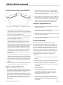
Installing Ceramic Radiants (model M60XR)
i
ii
iii
iv
ii
iii
iv
View: Looking into the front of broiler section.
i. Center Support ii. Ceramic Radiants iii. Side Support Rails iv. Burners
1. Pull forward the broiler rack of the ceramic broiler
section. Lift out rack insert and remove grease deflector
pan beneath rack assembly by raising it off the shoulder
bolts at the rear of the rack front plate.
2. Lower rack raising mechanism to its lowest position and
tie or wire the raising arm in place to avoid premature
release of the raising mechanism.
3. Start with the left side. Projections of the ceramic
radiants, will be down and the groove of the ceramic
radiants will be toward the center of the unit (See
sketch). Tilt the ceramic radiant to permit it to clear both
the side support and the center support and raise the
radiant above these 2 supports. Fit the groove of the
ceramic radiant into the flange of the center support
and lower its outer edge to rest on the top of the side
support. Slide this ceramic radiant to the rear and
repeat this with the two remaining ceramic radiants
overlapping.
4. Installation of the ceramic radiants on the right side is
similar to that as described above, except that you will
start from the front and work toward the rear. It may be
necessary to tilt the adjacent ceramic radiant upward
slightly to permit the interlocking of the final ceramic
radiants.
5. When all radiants have been installed, slide them as far
as possible to provide for proper flue movement.
Appliances Equipped With Casters
1. The installation shall be made with a connector that
complies with the Standard for Connectors for Moveable
Gas Appliances, ANSI Z21.69/CSA 6.16, Addenda
Z21.69B-2006/CSA 6.16B-2006 (or latest edition), and a
quick-disconnect device that complies with the Standard
for Quick Disconnects for Use with Gas Fuel, ANSI Z21.41/
CSA 6.9, Addenda Z21.41A-2005/CSA 6.16A-2005 (or
latest edition).
INSTALLATION Continued
2. The front casters on the appliance are equipped with
brakes to limit the movement of the appliance without
placing any strain on the connector or quick-disconnect
device or its associated piping.
3. Please be aware that the required restraint is attached to
a bracket (which is located on the rear caster closest to
the gas connection) and if disconnection of the restraint
is necessary, be sure to reconnect the device after the
appliance has been returned to its original position.
Appliances Equipped With Legs
1. Raise the front of the appliance an block. Do not lay the
appliance on its back.
2. Position leg insert in leg retainer opening and tap upward
until the insert seats at the collar ange.
3. Repeat leg insert installation for the other legs and adjust
all four legs to the same height.
4. Legs can be further adjusted to level the appliance and to
compensate for uneven ooring.
Testing & Adjustment
All ttings and pipe connections must be tested for
leaks. Use approved gas leak detectors, soap solution or
equivalent, checking over and around all the ttings and
pipe connections. DO NOT USE A FLAME! Accessibility to
all gas lines and ttings require that valve panel(s), lower
front panel(s), and/or oven rack(s) be removed. It may be
necessary to remove, or at least raise and securely prop
griddles, hot top, and/or top grates. All parts removed,
(including fasteners), should be stored safely for re-
installation.
1. Be sure that all valves and thermostats are in the “OFF”
position.
2. Turn on the main gas supply valve. Light all broiler pilots.
3. Leak test all valves and ttings as described at the
beginning of this section. Correct any leaks as required
and recheck.
4. Light the oven pilot.
5. If the range is equipped with an oven on/o valve
separate from the thermostat, turn this valve on. If
the oven thermostat dial has an “OFF” position the
thermostat is its own on/o valve.
6. In either case, now set the thermostat to 500°F (260°C).
Leak test all valves and ttings as described at the
beginning of this section. Correct any leaks as required
and recheck.

Part # 4515576 Rev 2 (01/15/16)Page 8
7. Shut o all valves and set thermostat dials to “OFF” or
lowest position.
All units are tested and adjusted at the factory, however,
burners and pilots should be checked upon installation and
adjusted if necessary.
CAUTION: Gas will ow to the top section burners even
if the broiler section pilots are not lit. Gas will not be
interrupted. It is the responsibility of the operator to
con rm the proper ignition of each burner as it is turned
on. Should ignition fail to occur 5 seconds after turning
a burner on, turn the burner o , wait 5 minutes, and try
again.
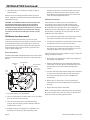
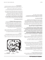
FDO Heavy Duty Oven control
The model FDO oven thermostat is a precision-made
instrument, carefully set at the factory to accurately control
oven temperatures from 150° to 500°F, (66° to 260°C). All
adjustments are accessible from the front of the appliance
after moving the dial. To remove the dial, grasp the outer
edges and pull straight out.
By-Pass Adjustment
The Robertshaw FDO snap/throttle thermostat requires that
the by-pass ame be properly adjusted. To adjust proceed as
follows:
4
5
0
5
0
0
5
5
0
1
5
0
3
0
0
2
5
0
3
0
0
3
5
0
4
0
0
Calibration
Lock Screws
By-pass Flame
Adjuster
Indicator Mark
Calibration
Plate
Dial
Stop
MODEL
FDO
1. Ensure pilot ame is lit and adjusted.
2. Turn oven temperature control to 200°F, (93°C), and allow
the oven to heat for three minutes.
3. Turn, the oven temperature control to the lowest
position, then turn slowly counter-clockwise until the
audible “click” is heard.
4. Making sure the oven temperature control dial is not
disturbed, turn the by-pass ame adjusting screw
clockwise to decrease, or counter-clockwise to increase
the ame on the burner to the lowest possible stable
ame. When properly adjusted, the by-pass ames will
cover the entire length of the burner.
Calibration Instructions
Field calibration is seldom necessary and should not
be resorted to unless experience with cooking results
undoubtedly indicate that the control is not maintaining
the temperature for which the dial is set. To check oven
temperatures when calibrating, use only a reliable mercury
thermometer, or preferably an oven pyrometer. To check
calibration, proceed as follows:
1. Place the thermocouple of the test instrument or reliable
mercury thermometer in the center of the oven.
2. Turn the oven temperature control knob to 400°F, (204°C),
and allow the oven to cycle at least three times.
3. Continue to monitor the oven temperature, recording
the readings at 5 minute intervals until three successive
readings are within 5°F, (2°C), of each other.
If the temperature does not read within 15°F, (8°C), of the dial
setting, recalibrate as follows.
1. Remove the oven temperature control dial, making sure
the setting is not disturbed.
2. Hold the calibration plate, (located directly behind the
control dial), and loosen the two calibration lock screws
until the plate can be rotated independently of the
control.
3. Turn the calibration plate until the temperature indicated
on the plate corresponds with the reading on the test
instrument. Hold the plate in place and tighten the
screws rmly.
4. Repeat step 3 in the previous section, checking the
temperature to ensure the adjustment has been made
properly.
5. Replace the temperature control dial.
NOTE: If adjustment of the calibration plate is prevented by
the position of the lock screws, the screws can be moved to
other holes that have been tapped for them.
INSTALLATION Continued

Part # 4515576 Rev 2 (01/15/16) Page 9
OPERATION
Broiler Section
Cast Iron Burner With Ceramic Tile - MX
Initial Operation:
When all gas connections have been inspected, proceed as
follows to put the unit into operation:
1. Open gas service valve located in your supply line.
2. With a lighted taper, light the broiler pilots located at the
front of the unit. There is one pilot per burner.
3. Pilot adjustment valves can be found on the manifold,
behind the control panel. The valves may be accessed
through holes in the control panel.
4. The pilot ame should be adjusted to provide a ame
7/8”(22mm) to 1”(25mm) in length.
Operation:
1. Turn the broiler valve to HIGH.
2. Immediately check ignition of the burners.
3. When ignition has been accomplished a blue ame will
cover the length of the burner.
4. Flames will ow upward over ceramic radiant bricks and
will glow red.
Shut-Down:
1. Turn all valves to the “OFF” position.
2. If the unit is to be shut down for an extended period of
time, close the in-line gas valve.
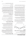
Infra-Red Burners -MXM, MXM
The GARLAND® Infra-Red Broiler is a direct radiant heavy
duty gas broiler utilizing four (4) extremely e cient gas
burners in each broiling section. The infra-red burners
provide for high speed broiling with rapid searing of product
so that natural juices and avor will be sealed in.
These special burners operate in a manner similar to that
of a conventional gas burner except that the radiation
surfaces consist of a series of ceramic blocks each containing
numerous small gas ports. These ceramic blocks are
connected utilizing a special compound that also seals all
seams of the radiating surface. The gas ame appears as a
red glow covering the entire ceramic surface.
A special wire mesh has been provided as an outside
surface beneath the ceramics to further increase the burner
e ciency. This mesh will provide for additional infra-red
energy.
Initial Operation:
1. Connect electrical supply.
2. Open gas service valve located in your supply line.
3. With a lighted taper, light the broiler pilots located at the
front of the unit. There is one pilot per pair of burners.
4. Pilot adjustment valves can be found on the manifold,
behind the control panel. The valves may be accessed
through holes in the control panel.
5. The pilots should be adjusted so that ame extends 1/2”
to 3/4” (12mm to 25mm) beyond the pilot shield.
Operation:
1. Switch on (1) the main power switch.
2. Turn the broiler valve to HIGH.
3. Immediately check ignition of the burners.
4. When ignition has been accomplished a blue ame will
cover the surface of the ceramics for 10-15 seconds.
5. The haze will disappear and the ceramics will glow red.
Shut-Down:
1. Turn all valves to the “OFF” position.
2. Switch o (0) the main power switch.
3. If the unit is to be shut down for an extended period of
time, close the in-line gas valve.

Part # 4515576 Rev 2 (01/15/16)Page 10
CAUTION: Should burner ignition fail within 5 seconds,
turn the burner valve o and repeat steps 1 through 5. If
ignition continues to fail, consult your factory authorized
service agency.
Ovens
Standard Ovens
Lighting:
1. Push in the main / pilot gas valve and turn it counter-
clockwise to the IGNITION position.
2. Lower the front kick panel.
3. Holding the oven gas valve fully in, press the red piezo
igniter button several times.
4. When the pilot burner is lit, continue holding in the oven
gas valve for 20 seconds, then release it. If the pilot goes
out, wait ve minutes and try again.
5. When the pilot ame is established, push the gas
valve in again and turn it counter-clockwise to the full
ON position, then set the thermostat to the desired
temperature.
Shut-Down:
1. Turn all valves to the OFF position and the safety device
will disengage within 60 seconds.
2. If the unit is to be shut down for an extended time, close
the in-line gas valve.
Re-lighting:
1. Turn all gas valves o .
2. Wait ve minutes.
3 Follow procedure under “Lighting” at left.
OPERATION Continued
Convection Ovens (RC)
Lighting:
Same as standard oven.
Start-Up:
1. Activate the power switch to COOK position.
2. Turn oven valve ON.
3. Turn thermostat to desired setting.
Cool Down:
1. Turn thermostat and oven valve OFF.
2. Open door.
3. Activate power to the COOL DOWN position.
The motor on your range convection oven is maintenance
free since it is constructed with self-lubricating sealed ball
bearings. It is designed to provide durable service when
treated with ordinary care. We have a few suggestions to
follow on the care of your motor.
A When the motor is operating, it cools itself internally by
air entering the rear of the motor case, provided proper
clearance has been allowed.
B. Since the blower wheel is in the oven cavity it is at the
same temperature as the oven. If the motor is stopped
while the oven is hot, the heat from the blower wheel is
conducted down the shaft and into the armature of the
motor. This action could shorten the motor life.
C. We recommend, at the end of the bake or roasting
period, when the oven will be idle for any period of time
or before shutting down completely, that the doors be
left open, and by use of the cool down position on the fan
switch, the fan continues to run for at least 20 minutes.
Note: The convection oven motor should never be turned
“OFF” during cooking or when the oven is “HOT”.

Part # 4515576 Rev 2 (01/15/16) Page 11
PRODUCT APPLICATION
Broiler
The following information is intended for use as a guide.
There are many variables that will e ect the operation. As an
example, the temperature of the product when it is placed
on the rack for broiling will e ect both the broiling time and
the quality of the nished product.
The broiler rack can be easily raised or lowered to provide for
the desired distance of the product from the heat source and
is readily pulled out for ease of loading and unloading.
It is suggested that all products be dipped in salt-free
oil before broiling to facilitate browning and to aid in
preventing the product from sticking to the broiler rack.
It must again be stressed that the times above are intended
as a general guide only. The technique of the operator and
experience with infra-red broiling will e ect time, burner
setting and rack position.
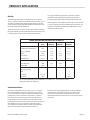
SUGGESTED BROILING TIME (EACH SIDE) IN MINUTES
Type of Product Thickness “
(mm)
Rare
Minutes
Medium
Minutes
Well Done
Minutes
Beef
Filet Mignon, Porterhouse 1 (25) 2 1/2 4 5 1/2
T-bone, Club Rib 1 1/2 (38) 2 1/2 4 5 1/2
Sirloin 2 (51) 3 1/2 5 1/2 6 1/2
Strip Sirloin 3/4 (19) 2 1/2 3 1/2 5
Ground Steak 1/2 (13) 1 1/2 2 2 1/2
Lamb
Loin, Rib Chops 1 (25) 3 1/2 4 1/2 -
Double Rib 2 (51) 4 6 -
Fish (Low burner setting,
low rack position)
*Fish - - - 5
Fish Steak 1/2 (13) - - 4
Fish Steak 1 (25) - - 4 1/2
* It is recommended that thin let- ounder, sole, uke, etc., - be folded over before
cooking to increase its thickness.
Convection Ovens
Generally, a temperature 25°F to 50°F (-4°C to 10°C) lower
than that speci ed in recipes for standard ovens should
be used. Cooking time may be reduced, depending on the
product. A 2% to 5% reduction in cook time is a general
rule. Keep a close check on any product being prepared
for the rst time. The size of the load, temperature of the
product going in and moisture content are the major factors
that in uence necessary cook times and temperatures.
Successfully prepared products should be recorded with
their times and temperatures for future reference.
Preheat the oven thoroughly before loading. It will take
approximately 15 minutes for the oven to reach 350°F
(177°C). Best results will be attained when the oven is
allowed to preheat for 30 minutes or more thorough heat
saturation.

Part # 4515576 Rev 2 (01/15/16)Page 12
Center the load on the oven racks to allow for proper heat
circulation around the sides. The oven will hold three, 18” x
26” (457mm x 660mm) sheet pans, six 12” x 20” x 2.5” (305mm
x 508mm x 64mm) steam table pans, or one 17.75”x 25.75”
(451mm x 654mm), roast pan. Never place pans directly on
the oven bottom. Always use the lowest rack position that will
allow air to circulate within the oven cavity. Load and unload
food as quickly as possible to prevent excessive temperature
drop. For even baking avoid using warped pans. Do not use
a deep pan for shallow cakes, cookies, etc., as heat circulation
across the top of these items is essential for browning. To
prevent excessive shrinkage, roast meat at a low temperature;
250°F to 325°F (121°C to 163°C).
When rethermalizing frozen products, preheat the oven 50°F
(10°C), higher than the cooking temperature to compensate
heat loss during and after loading. Return the thermostat to
the cooking temperature after loading.
To conserve energy, turn the oven o when not in use. If you
cover pans with aluminum foil, be sure to crimp it tightly
around the edges to prevent the foil from blowing o in
the oven. Any food or other or other matter that becomes
lodged in the fan must be removed as soon as the oven is
cool.
PRODUCT APPLICATION Continued
CARE & CLEANING
Stainless Steel
For routine cleaning just wash with hot water and detergent
solution. Wash just a small area at a time or the water will
evaporate leaving the chemicals behind causing streaking.
Rinse the washed area with a clean sponge dipped in a
sanitizing solution and wipe dry with soft clean cloth before
it can dry.
Use a paste (of water and a mild scouring powder) if you
have to, but never rub against the grain. All stainless steel has
been polished in one direction. Rub with the polish lines to
preserve the original nish. Then thoroughly rinse as before.
To prevent ngerprints there are several stainless steel
polishes on the market the leave and oily waxy lm. Do not
use on surfaces that will be in contact with food.
Stainless steel may discolor if overheated. These stains can
usually be removed by vigorous rubbing with a scouring
powder paste.
Use only stainless steel, wood or plastic tools if necessary
to scrape o heavy deposits of grease and oil. Do not use
ordinary steel scrapers or knives, as particles of the iron may
become imbedded and rust. STEEL WOOL SHOULD NEVER BE
USED.
Oven Interior (Porcelain Enamel)
NOTE: Disconnect line cord (if applicable) from power
supply before cleaning or servicing.
1. Before cleaning oven interior, remove all oven racks and
guides. Oven racks and guides can be cleaned with a mild
soap and warm water or run through a dishwasher.
2. The porcelain interior can be cleaned with oven cleaners
such as “Easy-O ” or “Dow Oven Cleaner”. Follow product
manufacturer’s instructions for proper use.
Broiler Section
General Cleaning
Remove, empty and wash the broiler grease drawer or
container at least once a day.
On a single broiler unit the grease drawer is located inside
the valve panel. On a double broiler the grease from the
upper broiler section drains into a container suspended
from the front of the unit. The grease from the lower broiler
section drains through the hopper into a grease drawer
located inside the valve panel.

Part # 4515576 Rev 2 (01/15/16) Page 13
Remove and clean the grid rack inserts and grease drip chute
daily. Pull the grid rack forward and lift the grease rack insert
out of the frame. Remove the grease drip chute by pulling it
forward out of the rack frame guides.
MXM
The M110XM lter should be removed and cleaned every
one to two days, depending on usage. The lter can be
cleaned by hand with dish detergent or run though the
dishwasher.
MX (R/RC/S/TM)
The M100 series of broilers have an air fan assisted motor
with a stainless steel lter screen to ensure a clean source of
primary air for your broiler burner combustion system. The
lter screen is located internally in the unit behind the broiler
grease tray assembly. It is recommended that you have your
service technician remove, clean and inspect this lter screen
when you do you regular equipment maintenance.
Grease Filter Removal on the M100X’s
1. It is recommended that this procedure be done when the
range is cool and not in use.
2. Remove all the control knobs.
3. Remove the grease tray.
4. Remove the screws for the valve panel and then remove
this panel.
5. Reach inside to access the grease lter screen. (Located
behind the grease tray area.) The protective cover over the
lter screen will snap o by carefully pulling downward by
hand.
6. Rinse the lter cover and lter with warm water and base
dish detergent soap.
7. Dry the lter screen and cover, then carefully snap back in
place.
8. Return the valve control panel with screws.
9. Ensure the grease tray has been replaced back into
position.
10. Carefully place the control knobs back into position.
CARE & CLEANING Continued
Instructions For Removal Of Grid Rack &
Grid Rack Frame
Remove the broiler grid racks as follows:
1. Bring the grid rack down to the lowest adjustment
position.
2. Pull the entire grid rack out of the broiler as far as
possible.
3. Remove grid rack grease drip chute (located below wire
rack) by grasping hold of the chute and pulling forward
out of the frame guides.
4. Remove wire racks by lifting the front of each wire rack
over the rack front plate.
5. Pull the empty grid rack frame assembly as far forward
as possible (until the stops hit the front of the carriage
assembly), lift up on the handle and pull the rack
frame forward so the stops clear the carriage assembly.
Continue pulling the rack frame forward until the rear
bearings reach the notches in the carriage tracks and lift
the rear of the rack up and out of the carriage; the entire
frame is now free from the unit.
6. Place the rack raising lever in the highest position for
safety purposes.
Before cleaning the hopper, replace the grease drawer
to receive any drippings and solid particles freed by the
cleaning. The additional internal grease diverter should be
removed from the top section and cleaned at this time. The
diverter is removed by raising the rack assembly and lifting
up the front of the diverter. After disengaging the screws at
the front of the unit, pull the diverter forward and remove
from the unit.
Carriage mechanisms should be kept clean, particularly
around the roller bearings. If the roller bearings have been
washed clean or appear to be dry, they should be lubricated
using salt-free vegetable oil or a non-toxic high temperature
bearing lubricant.
Infra-Red Burners must be cleaned periodically by a service
professional.

Part # 4515576 Rev 2 (01/15/16)Page 14
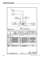
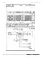
WIRING DIAGRAM

Part # 4515576 Rev 2 (01/15/16) Page 15
Notes

GARLAND
1177 KAMATO ROAD, MISSISSAUGA, ONTARIO, CANADA, L4W1X4
8884427526
WWW.GARLANDGROUP.COM
To learn how Manitowoc Foodservice and its leading brands can equip you, visit our global web site at
www.manitowocfoodservice.com, then discover the regional or local resources available to you.
©2014 Manitowoc Foodservice except where explicitly stated otherwise. All rights reserved.
Every new piece of Manitowoc Foodservice equipment comes with KitchenCare™ and you choose the level of service that meets
your operational needs from one restaurant to multiple locations.
StarCare – Warranty & lifetime service, certi ed OEM parts, global parts inventory, performance audited
ExtraCare — CareCode, 24/7 Support, online/mobile product information
LifeCare – Install & equipment orientation, planned maintenance, KitchenConnect™, MenuConnect
Talk with KitchenCare™ • 1-844-724-CARE • www.mtwkitchencare.com

Part # 4515576 Rev 2 (01/15/16) Page 15
SCHÉMA DE CÂBLAGE

Part # 4515576 Rev 2 (01/15/16)Page 14
5. Tirer l’ensemble du cadre vide aussi loin que possible
(jusqu’à ce que les butées touchent l’avant de l’ensemble
du chariot), soulever la poignée et tirer le cadre de
crémaillère vers l’avant de manière à ce que les butées
puissent se dégager de l’ensemble du chariot. Continuer
de tirer le cadre vers l’avant jusqu’à ce que les roulements
arrière atteignent les encoches des rails du chariot et
soulever l’arrière de la crémaillère et le sortir du chariot.
Tout le cadre est maintenant séparé de l’appareil.
6. Placer le levier de levage de crémaillère dans la position la
plus haute pour des raisons de sécurité.
ENTRETIEN ET NETTOYAGE Suite
Avant de nettoyer la trémie, remettre en place le tiroir à
graisse a n d’y recueillir toutes des particules ou gouttes
consécutives au nettoyage. Un dé ecteur à graisse interne
supplémentaire doit être retiré de la section supérieure
et être nettoyé à ce moment. Le dé ecteur est retiré en
soulevant l’ensemble de crémaillère et en soulevant la partie
avant du dé ecteur. Après avoir dégagé les vis à l’avant
de l’appareil, tirer le dé ecteur vers l’avant et le retirer de
l’appareil.
Les mécanismes du chariot doivent être maintenus propres,
surtout autour des roulements à rouleaux. Si les roulements
à rouleaux ont été lavés ou semblent être secs, ils doivent
être lubri és avec de l’huile végétale sans sel ou un lubri ant
pour roulements non toxique et résistant aux températures
élevées.
Les brûleurs à infrarouge doivent être nettoyés
périodiquement par un professionnel de service

Part # 4515576 Rev 2 (01/15/16) Page 13
L’acier inoxydable peut se décolorer s’il est trop chau é. Ces
taches peuvent être éliminées en frottant vigoureusement
avec de la crème à base de poudre à récurer.
Utiliser uniquement des outils en acier inoxydable, en
bois ou en plastique pour gratter si nécessaire les résidus
tenaces de graisses ou d’huiles. Ne pas utiliser de grattoirs
ni de couteaux en acier ordinaire, car des particules de fer
risquent de s’incruster dans les surfaces et rouiller. NE JAMAIS
UTILISER DE LAINE D’ACIER.
Intérieur Du Four (Fini En Émail Vitri é)
REMARQUE : Débrancher le cordon d’alimentation
électrique (le cas échéant) de la source électrique avant de
procéder au nettoyage ou à l’entretien.
1. Avant de nettoyer l’intérieur du four, enlever les grilles
et guides du four (en cas de base “four à convection”).
Ces pièces peuvent être nettoyées avec de l’eau tiède
savonneuse ou être mises dans le lave-vaisselle.
2 Les surfaces intérieures en émail vitri é peuvent être
nettoyées avec du produit de nettoyage pour fours
comme le “Easy-O ” ou “DOW Oven Cleaner”. Suivre les
instructions du fabricant du produit pour une utilisation
correcte.
Section Rôtissoire
Nettoyage Et Entretien
Retirer, vider et laver le tiroir ou contenant à graisse de la
rôtissoire une fois par jour au moins.
Pour un appareil à rôtissoire simple, le tiroir à graisse se
trouve à l’intérieur du panneau des robinets. Sur les appareils
à deux rôtissoires, la graisse de la section haute se vide dans
un contenant suspendu à l’avant de l’appareil. La graisse de
la section basse se vide par la trémie dans le tiroir à graisse se
trouvant à l’intérieur du panneau des robinets.
Retirer et nettoyer les inserts de crémaillère de grille et la
trémie à graisse tous les jours. Tirer la crémaillère de grille
vers l’avant et soulever l’insert hors du cadre. Retirer la trémie
à graisse en la tirant vers l’avant pour la libérer des guides du
cadre de crémaillère.
MXM
Le ltre de l’appareil M110XM doit être retiré et nettoyé tous
les jours ou tous les deux jours, en fonction de l’utilisation. Le
ltre peut être nettoyé à la main avec du produit de lavage à
vaisselle ou bien lavé dans le lave-vaisselle.
MX (R/RC/S/TM)
L’appareil M100 comporte un ventilateur pour la combustion
assistée avec un ltre en acier inoxydable a n d’assurer
une bonne qualité d’air au processus de combustion. Le
ltre est situé à l’intérieur, derrière le tirroir à graisse. Il est
recommandé qu’un technicien enlève, nettoie et inspecte le
ltre lors de l’entretien régulier de votre appareil.
Comment sortir le ltre.
1. Il est fortement recommandé que l’appareil soit refroidit
et non ulilisé.
2. Enlever tous les boutons de commande.
3. Enlever le tirroir à graisse.
4. Enlever les vis du panneau de commande, ensuite
enlever le panneau lui-même.
5. Enfoncer la main á l’intérieur pour acceder au ltre. (Situé
derrière la zone du tirroir á graise.) le capot protecteur du
ltre peut se détacher sans outil en tirant vers le bas.
6. Rincer le capot protecteur et le ltre avec de l’eau chaude
et du produit à vaisselle.
7. Sécher le ltre et le capot, ensuite les réinstaller avec
précaution.
8. Réinstaller le panneau de commande avec les vis.
9. S’assurer que le tirroir à graisse soit bien remis à sa place.
10 Remettre tous les boutons de commandes.
Instructions De Démontage De La Crémaillère Et
Du Cadre De Crémaillère De Grille
Retirer les crémaillères de grille de la rôtissoire comme suit :
1. Mettre la crémaillère de grille à la position la plus basse
possible de réglage.
2. Tirer l’ensemble de crémaillère de grille hors de la
rôtissoire aussi loin que possible.
3. Retirer la trémie à graisse de la crémaillère de grille (se
trouvant sous la grille) en saisissant la trémie et en la
tirant vers l’avant hors des guides du cadre.
4. Retirer les crémaillères de grilles en soulevant l’avant de la
chaque grille par-dessus la plaque avant de la crémaillère.
ENTRETIEN ET NETTOYAGE Suite
La page est en cours de chargement...
La page est en cours de chargement...
La page est en cours de chargement...
La page est en cours de chargement...
La page est en cours de chargement...
La page est en cours de chargement...
La page est en cours de chargement...
La page est en cours de chargement...
La page est en cours de chargement...
La page est en cours de chargement...
La page est en cours de chargement...
La page est en cours de chargement...
-
 1
1
-
 2
2
-
 3
3
-
 4
4
-
 5
5
-
 6
6
-
 7
7
-
 8
8
-
 9
9
-
 10
10
-
 11
11
-
 12
12
-
 13
13
-
 14
14
-
 15
15
-
 16
16
-
 17
17
-
 18
18
-
 19
19
-
 20
20
-
 21
21
-
 22
22
-
 23
23
-
 24
24
-
 25
25
-
 26
26
-
 27
27
-
 28
28
-
 29
29
-
 30
30
-
 31
31
-
 32
32


Garland 36ER33-88 Owner Instruction Manual
- Catégorie
- Cuisinières
- Taper
- Owner Instruction Manual
dans d''autres langues
- English: Garland 36ER33-88
Documents connexes
-
Garland E20 Series Manuel utilisateur
-
Garland M100XR Mode d'emploi
-
Garland Broiler Manuel utilisateur
-
-
-
-
-
U.S. Range E20 Series spécification
-
-
