NAPOLEON Acies Series Guide d'installation
- Taper
- Guide d'installation

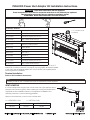
PVALX3/5 Power Vent Adaptor Kit Installation Instructions
Wolf Steel Ltd., 24 Napoleon Rd., Barrie, ON L4M 0G8 Canada • 1(866)820-8686 • www.napoleonreplaces.com
W415-2248 / 08.10.17
You will need:
Included in PVALX3:
W010-1777 Assembly, firestop spacer
W500-0551 Plate, dilution
W175-0309 Connector, reducer 5/8” to 4/7”
W750-0445 Wire, Linear Power Vent (3’)
Included in PVALX5:
W010-1777 Assembly, firestop spacer
W500-0551 Plate, dilution
W410-0029 Liner, 5’ stainless steel
W410-0017 Flex Liner, 7”
W175-0001 Coupler, 4”
W175-0013 Coupler, 7”
W175-0309 Connector, reducer 5/8” to 4/7”
W750-0444 Wire, Linear Power Vent (5’)
Your appliance uses 5” and 8” flexible venting. When installing the GPV, the 4”/7”
reducer (W175-0309) is required. The reducer must be properly secured and sealed
to unit using high temperature sealant W573-0007 Mill Pac (not supplied) before
continuing with vent installation.
INSTALLER: Leave these instructions with the appliance.
These instructions are to be used in conjunction with those for the GPV and your appliance.
This information supercedes that your appliance installation manual.
CONSUMER: Retain these instructions for future reference.
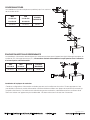
Terminal Installation
Refer to GPV installation instructions
4” x 7” Reducer (must
be sealed)
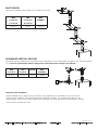
It is recommended that the gas power vent be used with a gas appliance that is
equipped with Electronic Ignition. When installing the venting, these parameters
supersede the Vent Installation Section in the appliance's Installation and
Operating Instructions, use the following guidelines:
Maximum horizontal vent run with no rise is 80 feet total.
H = HORIZONTAL RUN V = VERTICAL RUN
MAX H+V MIN H+V MAX ELBOWS
80 FEET 10 FEET SIX 90°
V
H2
H1
V
D
Elbow 1
Elbow 2
Elbow 3
Elbow 5
Elbow 4
Elbow 6
H3
H2
H1
V1
V2
V3
VENT LENGTHS
If installing a PVALX5, the 4” stainless liner must be used directly off the appliance.
note:

Wolf Steel Ltd., 24 Napoleon Rd., Barrie, ON L4M 0G8 Canada • 1(866)820-8686 • www.napoleonreplaces.com
W415-2248 / 08.10.17
V
H2
H1
V
D
Elbow 1
Elbow 2
Elbow 3
Elbow 5
Elbow 4
Elbow 6
H3
H2
H1
V1
V2
V3
Downward venting installations are only allowed when the appliance is set to Intermittent Pilot Ignition (I.P.I.) Electronic Ignition
(E.I.). If an anti-condensation switch is being used, downward vertical venting is not allowed.
Multi-elbow installations are possible up to a maximum of six 90°.
MAX
V1+V2+V3+
H1+H2+H3
MIN
V1+V2+V3+
H1+H2+H3
MAX
ELBOWS
80 FEET 10 FEET SIX 90°
MULTI ELBOW
V
H2
H1
V
D
Elbow 1
Elbow 2
Elbow 3
Elbow 5
Elbow 4
Elbow 6
H3
H2
H1
V1
V2
V3
MAX
H1+H2+V
MIN
H1+H2+V
MAX D MAX
ELBOWS
80 FEET 10 FEET 8 FEET SIX 90°
DOWNWARD VERTICAL VENTING
77.4
Vertical installations may display a very active fl ame. If this appearance is not desirable, the vent exit may be
restricted using a restrictor vent kit (the appropriate kit has been supplied). This will reduce the velocity of the
exhaust gases, slowing down the fl ame pattern and creating a more traditional gentle fl ame appearance. Specifi c
instructions are included with the kit.
Restrictor Plate Installation
Certain

Wolf Steel Ltd., 24 Napoleon Rd., Barrie, ON L4M 0G8 Canada • 1(866)820-8686 • www.napoleonreplaces.com
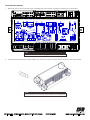
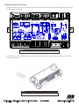
1. Identify all wires to avoid confusion when reinstalling the control board. Disconnect all wires from control board.
Wire connections will only fit in designated locations.
note:
It may be easier to remove the control board from the appliance.
note:
LAMP
COMFORT
FAN
2. Using a flat head screwdriver carefully release the 4 tabs (2 per side) to remove the top cover from the control board.
Control Board Installation
W415-2248 / 08.10.17

3. Remove the jumper (JP1) from the control board. (This activates the power vent function).
4. Replace the control board cover and all wire harness connections except for the power cord (x1), it will be replaced with
the new wire harness (provided).
5. Connect the new wire harness in locations (x1) and (x12) as shown on the top of the control board.
6. Cut the yellow wire loop (APS) located in (x5) and connect them to the orange and red wires of the new wire harness and
secure grounds to the base.
7. Connect the other end to the wire harness provided with the GPV.
8. Test your appliance by turning it on using the remote.
Wolf Steel Ltd., 24 Napoleon Rd., Barrie, ON L4M 0G8 Canada • 1(866)820-8686 • www.napoleonreplaces.com
W415-2248 / 08.10.17
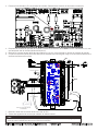
BATTERY HOLDER COMPLETE
LAMP
COMFORT
FAN
WITH PROGRAM BUTTON
WIRE HARNESS
THERMAL SENSORTHERMAL SENSOR
PILOT
BLACK
WHITE
GREEN
BLACK
GPV
RED
ORANGE
(APS)
YELLOW
LOOP CUT
IN HALF
RESET BUTTON
There is a 15 second pre-purge before the burner will light and a 120 second post-purge once the appli-
ance is turned off before the blower stops.
note:
X5
X1
X12

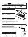
Instructions d’Installation de la Terminaison Mécanique PVALX3/5
Wolf Steel Ltd., 24 Napoleon Rd., Barrie, ON L4M 0G8 Canada • 1(866)820-8686 • www.napoleonreplaces.com
W415-2248 / 08.10.17
Vous aurez besoin:
L’ensemble PVALX3 comprend:
W010-1777 Assemblage de l’espaceur coupe-feu
W500-0551 Plaque de dilution
W175-0309 Raccord, réducteur 5/8” à 4/7”
W750-0445 Fil, Terminaison Mécanique Linéaire (3’)
L’ensemble PVALX5 comprend:
W010-1777 Assemblage de l’espaceur coupe-feu
W500-0551 Plaque de dilution
W410-0029 Revêtement, 5’ en acier inoxydable
W410-0017 Revêtement flexible, 7”
W175-0001 Attelage, 4”
W175-0013 Attelage, 7”
W175-0309 Raccord, réducteur 5/8” à 4/7”
W750-0444 Fil, Terminaison Mécanique Linéaire (5’)
Votre appareil utilise les conduits flexibles de 5” et de 8”. Quand le GPV est installé,
vous devez utiliser un réducteur 4”/7” (W175-0309). Le réducteur doit être fixé et scellé
à l’appareil avec du scellant à haute température Mill Pac W573-0007 (non fourni)
avant de continuer l’installation de l’évacuation.
INSTALLATEUR: Laissez ces instructions avec l’appareil.
Ces instructions doivent être utilisées conjointement avec celles du GPV et votre appareil.
Cet information remplacent les instructions d’installation dans le manuel de votre appareil.
PROPRIÉTAIRE: Conservez ce manuel pour consultation ultérieure.
Installation de la Terminaison
Référez-vous aux instructions d’installation du GPV
Réducteur 4” x 7” (doit
être scellé)
Il est conseillé d’utiliser la terminaison mécanique avec un appareil au gaz muni
d’un allumage électronique. Lors de l’installation de l’évacuation, les paramètres
suivants remplaceront la section « installation des évents » dans le manuel
d’installation/opération, utiliser les directives suivantes:
La déviation horizontale maximale sans élévation est de 80 pieds en tout.
H = COURSE HORIZONTALE V = COURSE VERTICALE
MAX H+V MIN H+V COUDES MAX
80 PIEDS 10 PIEDS SIX 90°
V
H2
H1
V
D
Elbow 1
Elbow 2
Elbow 3
Elbow 5
Elbow 4
Elbow 6
H3
H2
H1
V1
V2
V3
LONGUEURS DES CONDUITS D’ÉVACUATION
Si vous installé le PVALX5, le revêtement inoxydable de 4” doit être utiliser directement à partir de l’appareil.
note:

Wolf Steel Ltd., 24 Napoleon Rd., Barrie, ON L4M 0G8 Canada • 1(866)820-8686 • www.napoleonreplaces.com
W415-2248 / 08.10.17
V
H2
H1
V
D
Elbow 1
Elbow 2
Elbow 3
Elbow 5
Elbow 4
Elbow 6
H3
H2
H1
V1
V2
V3
Les installations d’évacuations descendantes sont seulement permises quand l’appareil est réglé à Allumage intermittent de
la veilleuse (I.P.I.) Allumage électronique (E.I.). L’évacuation verticale descendante n’est pas permise avec l’utilisation
d’un interrupteur anticondensation.
Les installations à coudes multiples sont possibles jusqu’à un maximum
de six coudes de 90°.
MAX
V1+V2+V3+
H1+H2+H3
MIN
V1+V2+V3+
H1+H2+H3
COUDES
MAXIMUM
80 PIEDS 10 PIEDS SIX 90°
COUDES MULTIPLES
V
H2
H1
V
D
Elbow 1
Elbow 2
Elbow 3
Elbow 5
Elbow 4
Elbow 6
H3
H2
H1
V1
V2
V3
MAX
H1+H2+V
MIN
H1+H2+V
MAX D COUDES
MAXIMUM
80 PIEDS 10 PIEDS 8 PIEDS SIX 90°
ÉVACUATION VERTICALE DESCENDANTE
77.4
Certaines confi gurations d’évacuation verticales peuvent avoir une fl amme très active. Si cette apparence n’est
pas désirée, la sortie du conduit d’évacuation doit être réduite en utilisant une plaque de restriction (la trousse ap-
propriée a été fournie). Ceci diminuera la vélocité des gaz de combustion, ralentissant ainsi le mouvement de la
fl amme et créant une apparence plus traditionnelle. Les instructions sont incluses avec l’ensemble.
Installation de la plaque de restriction

Wolf Steel Ltd., 24 Napoleon Rd., Barrie, ON L4M 0G8 Canada • 1(866)820-8686 • www.napoleonreplaces.com
1. Identifié toutes les fils pour prévenir confusion lorsque le panneau de contrôle doit être réinstallé. Débranchez toutes les
fils du panneau de contrôle.
Connexions des câbles ne rentrera pas dans des endroits désignés.
note:
Il peut être plus facile d’enlever le panneau de contrôle.
note:
LAMP
COMFORT
FAN
2. Avec l’aide d’un tournevis à tête plâte, soigneusement relâcher les 4 pattes (2 par côté) pour enlever le couvercle du
panneau de contrôle.
Installation du Panneau de Contrôle
W415-2248 / 08.10.17

3. Enlever le fil de dérivation (JP1) du panneau de contrôle. (Cela activera le fonction du terminaison mécanique).
4. Remplacer le couvercle du panneau de contrôle et toutes les connections de fils sauf le cordon d’alimentation (x1); cela
sera remplacer avec le nouveau harnais de fils (fourni).
5. Branchez le nouveau harnais de fils dans les locations (x1) et (x12) comme illustré sur le haut du panneau de contrôle.
6. Coupez le boucle de fil jaune (APS) situé dans (x5) et branchez-le au fils orange et rouge sur le nouveau harnais de fils et
sécurisez les fils de terre au base.
7. Branchez l’autre côté au harnais de fils fourni avec le GPV.
8. Testez votre appareil en le tournant par utilisation du télécommande.
Wolf Steel Ltd., 24 Napoleon Rd., Barrie, ON L4M 0G8 Canada • 1(866)820-8686 • www.napoleonreplaces.com
W415-2248 / 08.10.17
BATTERY HOLDER COMPLETE
LAMP
COMFORT
FAN
WITH PROGRAM BUTTON
WIRE HARNESS
THERMAL SENSORTHERMAL SENSOR
PILOT
BLACK
WHITE
GREEN
BLACK
GPV
RED
ORANGE
(APS)
YELLOW
LOOP CUT
IN HALF
RESET BUTTON
Il y a une deuxième purge de 15 secondes préalable avant que le brûleur s’allume et une purge après 120
seconds quand l’appareil est éteint avant l’arrêt de la soufflerie.
note:
X5
X1
X12
ROUGE
VERT
BLANC
NOIR
NOIR
HARNAIS DE FILS
CAPTEUR THERMIQUE
VEILLEUSE
CAS DE PILES FOURNI AVEC BOUTON
DE PROGRAMME
-
 1
1
-
 2
2
-
 3
3
-
 4
4
-
 5
5
-
 6
6
-
 7
7
-
 8
8


NAPOLEON Acies Series Guide d'installation
- Taper
- Guide d'installation
dans d''autres langues
Documents connexes
-
NAPOLEON Vector Series Guide d'installation
-
NAPOLEON LVX62N2X Manuel utilisateur
-
-
-
NAPOLEON Bayfield GDS25N-1 Le manuel du propriétaire
-
-
-
-