
In-Sight
®
CIO-MICRO and
Quick Start Guide
CIO-MICRO-CC I/O Modules


1
P/N 597-0129-01 Copyright © 2010 Cognex Corporation. All Rights Reserved.
Declaration of Conformity
Manufacturer Cognex Corporation
One Vision Drive
Natick, MA 01760 USA
Declares this
-marked Machine Vision System Product
Product Type: Type 821-0016-1R, Type 821-0016-2R, Type 821-0017-1R, Type 821-0017-2R
Complies With: 2004/108/EC
Compliance
Standards:
EN 55022:2006 Class A
EN 61000-6-2:2005
EN 61000-3-2:2006
EN 61000-3-3:1995 +A1:2001 +A2:2005
European
Representative:
COGNEX INTERNATIONAL
Immeuble “Le Patio”
104 Avenue Albert 1er
92563 Rueil Malmaison Cedex - France
Safety and Regulatory
FCC FCC Part 15, Class A
This device complies with Part 15 of the FCC Rules. Operation is subject to the following two
conditions: (1) This device may not cause harmful interference, and (2) this device must accept any
interference received, including interference that may cause undesired operation.
This equipment generates, uses, and can radiate radio frequency energy and, if not installed
and used in accordance with the instruction manual, may cause harmful interference to radio
communications. Operation of this equipment in a residential area is likely to cause harmful
interference in which case the user will be required to correct the interference at their own expense.
KCC CGX-CIO-MICRO (CIO-MICRO only)
NRTL TÜV SÜD AM SCC/NRTL OSHA Scheme for UL/CAN 60950-1
CB TÜV SÜD AM, IEC/EN 60950-1. CB report available upon request.
RoHS RoHS 6 Compliant
Note: For the most up-to-date regulations and conformity information, refer to the In-Sight online support site:
http://www.cognex.com/Support/InSight

2
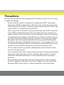
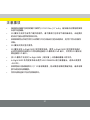
Precautions
Observe these precautions when installing the I/O module to reduce the risk of injury
or equipment damage:
Power for the I/O module is intended to be supplied by a NRTL listed power •
supply with a 24VDC output rated at 750 mA or more, a maximum short circuit
current rating of less than 8A, a maximum power rating of less than 100VA, and
marked Class 2 or Limited Power source (LPS).
Never connect the I/O module to a power source other than 24VDC connected •
to the 24VDC terminal block pins on the I/O module. Any other connection or
voltage creates a risk of fi re or shock and can damage the module components.
The shield ground connections of the RS-232 port, LAN port, PoE port, I/O port •
and Frame Ground terminal are internally connected. The system grounding is
designed to be at a zero ground potential; this zero ground potential extends
through the cable and to peripheral equipment (e.g., a vision system, PLC, etc.).
To ensure safe operating conditions, it is strongly recommended that all ground
connections are checked to ensure that a zero ground potential is met.
The I/O module must be grounded by attaching the module’s Frame Ground •
terminal to a frame ground.
Do not install the I/O module in areas directly exposed to environmental hazards •
such as excessive heat, dust, moisture, humidity, impact, vibration, corrosive
substances, fl ammable substances, or static electricity without a protective
enclosure.
Route all cables and wires away from high-voltage power sources to reduce •
the risk of damage or malfunction due to over-voltage, line noise, electrostatic
discharge (ESD), power surges, or other irregularities in the power supply.

3
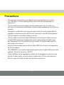
Precautions
The maximum torque that can be applied to the terminal block connectors •
is 0.1921 Nm (1.7 in-lb). Applying torque above this limit can damage the
connectors.
The I/O module does not contain user-serviceable parts. Do not make any •
electrical or mechanical modifi cations. Unauthorized modifi cations may void your
warranty.
Changes or modifi cations not expressly approved by the party responsible for •
regulatory compliance could void the user’s authority to operate the equipment.
The I/O module is intended for indoor use only.•
The I/O module supports In-Sight 5600 series vision systems. When using an •
In-Sight 5600 series vision system, the vision system’s Ethernet cable must
be connected to the I/O module’s PoE port and its I/O Module cable must be
connected to the I/O port.
Access to the encoder inputs on the In-Sight 5604 (Line Scan) is not supported •
by the I/O module.
HS COMMON is not used for high-speed outputs with In-Sight 5600 series vision •
systems. The return must use –24VDC.
Cable shielding can be degraded or cables can be damaged or wear out more •
quickly if a bend radius or service loop is tighter than 10X the cable diameter.
Service loops should be included with all cable connections.•

4
1
3
4
OR
2
8
7
6
5
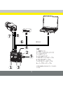
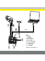
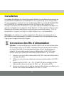
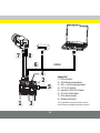
Legend*
1 = Power Wires
2 = Frame Ground Wire
3 = Input and Output Wires
4 = CC-Link Wires
5 = RS-232 Serial Cable
6 = RJ-45 LAN Cable
7 = I/O Module Cable
8 = Ethernet Cable
*The legend numbers also correspond with the
numbered Installation steps.

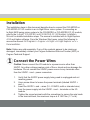
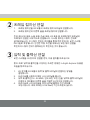
5
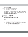
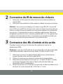
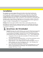
1
Connect the Power Wires
Caution: Never connect the I/O module to a power source other than
24VDC. Any other voltage creates a risk of fi re or shock and can damage the
hardware. Do not connect the 24VDC power source to any terminals other
than the 24VDC + and – power connectors.
Verify that the 24VDC power supply being used is unplugged and not 1.
receiving power.
Use a screw driver to loosen the power terminals (labeled 24VDC + 2.
and –).
Insert the 24VDC + and – wires (16 - 22 AWG, solid or stranded wire) 3.
from the power supply into the 24VDC + and – terminals on the I/O
module.
Tighten the screw terminals with the screwdriver to secure the wire leads 4.
in the terminal block; the maximum torque is 0.1921 Nm (1.7 in-lb).
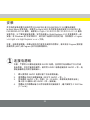
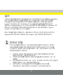
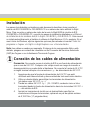
Installation
The installation steps in this document describe how to connect the CIO-MICRO or
CIO-MICRO-CC I/O module to an In-Sight Micro vision system. If connecting an
In-Sight 5600 series vision system to the CIO-MICRO or CIO-MICRO-CC I/O module,
refer to the In-Sight
®
CIO-MICRO and CIO-MICRO-CC I/O Modules Installation
Manual for detailed installation steps. The manual is installed with In-Sight Explorer
4.3.0 and higher software. From the Windows Start menu, select the following to
access the manual: All Programs > Cognex > In-Sight > In-Sight Explorer x.x.x >
Documentation.
Note: Cables are sold separately. If any of the contents appear to be missing or
damaged, immediately contact your Cognex Authorized Service Provider (ASP) or
Cognex Technical Support.

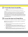
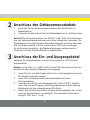
6
3
Connect the Input and Output Wires
If connecting the vision system to an I/O device, complete the following steps.
Note: Refer to the In-Sight
®
Explorer Help fi le for details on confi guring the
discrete input and output lines.
Determine how I/O devices will be connected to the I/O module’s input 1.
and output terminals.
Use a screw driver to loosen the appropriate screw terminals.2.
Connect the input and output wires (16 - 22 AWG, solid or stranded wire) 3.
to the input and output terminals and the other end of the cables to the
applicable I/O device.
Tighten the screw terminals with the screwdriver to secure the wire leads 4.
in the terminal block; the maximum torque is 0.1921 Nm (1.7 in-lb).
2
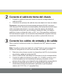
Connect the Frame Ground Wire
Connect a frame ground wire to the I/O module’s Frame Ground 1.
terminal.
Connect the other end of the frame ground wire to frame ground.2.
Caution: The shield ground connections of the RS-232 port, LAN port, PoE
port, I/O port and Frame Ground terminal are internally connected. The
system grounding is designed to be at a zero ground potential; this zero
ground potential extends through the cable and to peripheral equipment (e.g.,
a vision system, PLC, etc.). To ensure safe operating conditions, it is strongly
recommended that all ground connections are checked to ensure that a zero
ground potential is met.

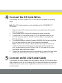
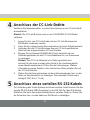
7
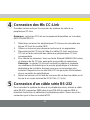
4
Connect the CC-Link Wires
If connecting the vision system to a CC-Link device, complete the following
steps.
Note: The CC-Link terminals are only available on the CIO-MICRO-CC
I/O module.
Determine how CC-Link devices will be connected to the I/O module’s 1.
CC-Link terminals.
Use a screw driver to loosen the appropriate screw terminals.2.
Connect the CC-Link wires (using a CC-Link specifi ed cable) to the 3.
CC-Link terminals and the other end of the cables to the applicable
CC-Link devices.
To reduce emissions, attach a Steward 28A0640-0A2 ferrite around the 4.
CC-Link wire bundle, as close to the connector as possible.
Note: The CC-Link network is daisy-chained and requires a terminal
resistor for the fi rst and last devices in the chain. Make certain that
your connections are correct. Refer to the CC-Link web site for more
information and specifi cation details.
Tighten the screw terminals with the screwdriver to secure the wire leads 5.
in the terminal block; the maximum torque is 0.1921 Nm (1.7 in-lb).
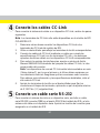
5
Connect an RS-232 Serial Cable
If connecting the vision system to a serial device, plug an RS-232 serial cable
(DB9 connector) into the I/O module’s RS-232 port and connect the other end
of the cable to the serial device. Tighten the connector screws to secure it to
the I/O module.

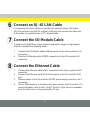
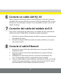
8
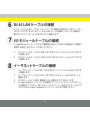
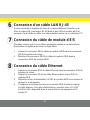
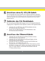
7
Connect the I/O Module Cable
If using the In-Sight Micro vision system’s acquisition trigger or high-speed
outputs, complete the following steps.
Connect the I/O Module cable’s M8 connector to the vision system’s I/O 1.
connector.
Plug the I/O Module cable’s DB15 connector into the I/O module’s I/O 2.
connector.
8
Connect the Ethernet Cable
Connect the Ethernet cable’s M12 connector to the vision system’s PoE 1.
connector.
Connect the Ethernet cable’s RJ-45 connector to the I/O module’s PoE 2.
port.
Restore power to the I/O module’s 24VDC power supply and turn it on if 3.
necessary.
Use In-Sight Explorer to confi gure the vision system and I/O module. For 4.
more information, refer to the In-Sight
®
Explorer Help, which is available
from the Help menu or by pressing the F1 key.
6
Connect an RJ-45 LAN Cable
If connecting the vision system to an Ethernet network, plug a LAN cable
(RJ-45 connector) into the I/O module’s LAN port and connect the other end
of the cable to a switch/router or PC, as applicable.

9
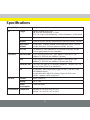
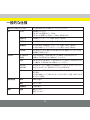
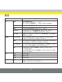
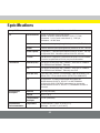
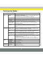
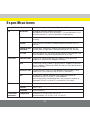
Specifi cations
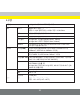
Compatibility In-Sight Micro and 5600 series vision systems
I/O Trigger Optically isolated trigger input;
ON: 20 to 28V (24V nominal), < 7.5mA;
OFF: 0 to 3V (8V nominal threshold), < 250μA; Resistance ~10,000 Ohms
Inputs 8 general purpose, optically isolated discrete (Maximum 30VDC, 10.4 mA)
Outputs 8 general purpose, optically isolated discrete (Maximum 30VDC, 100 mA)
High Speed
Outputs
In-Sight Micro: 2 optically isolated discrete (Maximum 28VDC, 100 mA)
In-Sight 5600 series: 2 discrete (Maximum 28VDC, 200 mA)
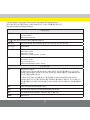
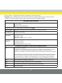
CC-Link CIO-MICRO-CC only. Standard CC-Link terminal connectors. See the
CC-Link specifi cations for more information.
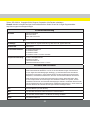
Connectors Ethernet (LAN) RJ-45 10/100 port (IEEE 802.3 Type 10Base-T; IEEE 802.3u Type
100Base-TX; IEEE 802.3ab 100Base-T Ethernet)
PoE RJ-45 10/100 port (IEEE 802.3 Type 10Base-T; IEEE 802.3u Type
100Base-TX; IEEE 802.3ab 100Base-T Ethernet) with PoE
Serial (RS-232) 1 RS-232C port (4800 to 115,200 baud), 8 data bits, 1 stop bit, RxD, TxD,
and fl ow control (RTS/CTS & XON/XOFF)
I/O In-Sight Micro: DB15 I/O providing Trigger, HS OUT 0, HS OUT 1 and
HS COMMON signals.
In-Sight 5600 series: DB15 I/O providing Trigger, HS OUT 0 and
HS OUT 1 signals, 24VDC and ground.
Electrical Current 600mA (maximum)
Voltage 24V +/- 10%
Power
Consumption
14.4W (maximum)
Environmental Temperature Operating: 0°C to 45°C (32°F to 113°F)
Storage: -10°C to 65°C (14°F to 149°F)

10
“”

11

12

13
1
3
4
2
8
7
6
5

14
1

15
2
3

16
4
5

17
6
7
8

18
La page est en cours de chargement...
La page est en cours de chargement...
La page est en cours de chargement...
La page est en cours de chargement...
La page est en cours de chargement...
La page est en cours de chargement...
La page est en cours de chargement...
La page est en cours de chargement...
La page est en cours de chargement...
La page est en cours de chargement...
La page est en cours de chargement...
La page est en cours de chargement...
La page est en cours de chargement...
La page est en cours de chargement...
La page est en cours de chargement...
La page est en cours de chargement...
La page est en cours de chargement...
La page est en cours de chargement...
La page est en cours de chargement...
La page est en cours de chargement...
La page est en cours de chargement...
La page est en cours de chargement...
La page est en cours de chargement...
La page est en cours de chargement...
La page est en cours de chargement...
La page est en cours de chargement...
La page est en cours de chargement...
La page est en cours de chargement...
La page est en cours de chargement...
La page est en cours de chargement...
La page est en cours de chargement...
La page est en cours de chargement...
La page est en cours de chargement...
La page est en cours de chargement...
La page est en cours de chargement...
La page est en cours de chargement...
La page est en cours de chargement...
La page est en cours de chargement...
La page est en cours de chargement...
La page est en cours de chargement...
La page est en cours de chargement...
La page est en cours de chargement...
La page est en cours de chargement...
La page est en cours de chargement...
La page est en cours de chargement...
La page est en cours de chargement...
La page est en cours de chargement...
-
 1
1
-
 2
2
-
 3
3
-
 4
4
-
 5
5
-
 6
6
-
 7
7
-
 8
8
-
 9
9
-
 10
10
-
 11
11
-
 12
12
-
 13
13
-
 14
14
-
 15
15
-
 16
16
-
 17
17
-
 18
18
-
 19
19
-
 20
20
-
 21
21
-
 22
22
-
 23
23
-
 24
24
-
 25
25
-
 26
26
-
 27
27
-
 28
28
-
 29
29
-
 30
30
-
 31
31
-
 32
32
-
 33
33
-
 34
34
-
 35
35
-
 36
36
-
 37
37
-
 38
38
-
 39
39
-
 40
40
-
 41
41
-
 42
42
-
 43
43
-
 44
44
-
 45
45
-
 46
46
-
 47
47
-
 48
48
-
 49
49
-
 50
50
-
 51
51
-
 52
52
-
 53
53
-
 54
54
-
 55
55
-
 56
56
-
 57
57
-
 58
58
-
 59
59
-
 60
60
-
 61
61
-
 62
62
-
 63
63
-
 64
64
-
 65
65
-
 66
66
-
 67
67


Cognex In-Sight CIO-MICRO Guide de démarrage rapide
- Taper
- Guide de démarrage rapide
- Ce manuel convient également à
dans d''autres langues
Documents connexes
-
Cognex In-Sight Micro 1010C Manuel utilisateur
-
-
Cognex In-Sight 7430 Guide de démarrage rapide
-
Cognex In-Sight 5100 Manuel utilisateur
-
-
Cognex 1AAB Manuel utilisateur
-
-
-
