Victron energy SmartSolar MPPT 150/35 Le manuel du propriétaire
- Taper
- Le manuel du propriétaire

Manual
EN
Handleiding
NL
Manuel
FR
Anleitung
DE
Manual
ES
Användarhandbok
SE
Appendix
SmartSolar charge controller MPPT 150/35


1
EN NL FR DE ES SE Appendix
1. General Description
1.1 Charge current up to 35A and PV voltage up to 150V
The SmartSolar MPPT 150/35 charge controller is able to
charge a lower nominal-voltage battery from a higher nominal
voltage PV array.
The controller will automatically adjust to a 12V, 24V or a 48V
nominal battery voltage.
1.2 Ultra-fast Maximum Power Point Tracking (MPPT)
Especially in case of a clouded sky, when light intensity is
changing continuously, an ultra fast MPPT controller will
improve energy harvest by up to 30% compared to PWM charge
controllers and by up to 10% compared to slower MPPT
controllers.
1.3 Advanced Maximum Power Point Detection in case of
partial shading conditions
If partial shading occurs, two or more maximum power points
may be present on the power-voltage curve.
Conventional MPPTs tend to lock to a local MPP, which may not
be the optimum MPP.
The innovative SmartSolar algorithm will always maximize
energy harvest by locking to the optimum MPP.
1.4 Outstanding conversion efficiency
No cooling fan. Maximum efficiency exceeds 98%. Full output
current up to 40°C (104°F).
1.5 Extensive electronic protection
Over-temperature protection and power derating when
temperature is high.
PV short circuit and PV reverse polarity protection.
PV reverse current protection.
1.6 Internal temperature sensor
Compensates absorption and float charge voltages for
temperature.
1.7 Automatic battery voltage recognition
The controller will automatically adjust itself to a 12V, 24V or a
48V system one time only. If a different system voltage is
required at a later stage, it must be changed manually, for
example with the Bluetooth app, see section 1.11.

2
1.8 Flexible charge algorithm
Fully programmable charge algorithm, and eight preprogrammed
algorithms, selectable with a rotary switch.
1.9 Adaptive three step charging
The SmartSolar MPPT Charge Controller is configured for a three
step charging process: Bulk – Absorption – Float.
1.9.1. Bulk
During this stage the controller delivers as much charge current
as possible to rapidly recharge the batteries.
1.9.2. Absorption
When the battery voltage reaches the absorption voltage setting,
the controller switches to constant voltage mode.
When only shallow discharges occur the absorption time is kept
short in order to prevent overcharging of the battery. After a deep
discharge the absorption time is automatically increased to make
sure that the battery is completely recharged. Additionally, the
absorption period is also ended when the charge current
decreases to less than 2A.
1.9.3. Float
During this stage, float voltage is applied to the battery to
maintain it in a fully charged state.
When the battery voltage drops below float voltage during at least
1 minute a new charge cycle will be triggered.
1.9.4. Equalization
See section 3.8.
1.10 Remote on-off
The MPPT 150/35 can be controlled remotely by a VE.Direct non
inverting remote on-off cable (ASS030550300). An input HIGH
(Vi > 8V) will switch the controller on, and an input LOW (V < 2V,
or free floating) will switch the controller off.
Application example: on/off control by a VE.Bus BMS when
charging Li-ion batteries.

3
EN NL FR DE ES SE Appendix
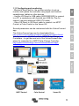
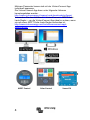
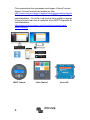
1.11 Configuring and monitoring
- Bluetooth Smart built-in: the wireless solution to set-up,
monitor and update the controller using Apple and Android
smartphones, tablets or other devices.
- Use the VE.Direct to USB cable (ASS030530000) to connect
to a PC, a smartphone with Android and USB On-The-Go
support (requires additional USB OTG cable).
- Use a VE.Direct to VE.Direct cable to connect to a MPPT
Control, a Color Control or the Venus GX.
Several parameters can be customized with the VictronConnect
app.
The VictronConnect app can be downloaded from
http://www.victronenergy.nl/support-and-downloads/software/
Use the manual – VictronConnect - MPPT Solar Charge
Controllers – to get the most out of the VictronConnect App
when it’s connected to a MPPT Solar Charge Controller:
http://www.victronenergy.com/live/victronconnect:mppt-
solarchargers
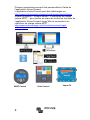
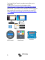
MPPT Control
Color Control
Venus GX

4
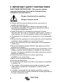
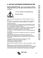
2. IMPORTANT SAFETY INSTRUCTIONS
SAVE THESE INSTRUCTIONS - This manual contains
important instructions that shall be followed during
installation and maintenance.
● Please read this manual carefully before the product is
installed and put into use.
● This product is designed and tested in accordance with
international standards. The equipment should be used for
the designated application only.
● Install the product in a heatproof environment. Ensure
therefore that there are no chemicals, plastic parts, curtains or
other textiles, etc. in the immediate vicinity of the equipment.
● The product is not allowed to be mounted in a user accessible
area.
● Ensure that the equipment is used under the correct operating
conditions. Never operate it in a wet environment.
● Never use the product at sites where gas or dust explosions
could occur.
● Ensure that there is always sufficient free space around the
product for ventilation.
● Refer to the specifications provided by the manufacturer of the
battery to ensure that the battery is suitable for use with this
product. The battery manufacturer's safety instructions should
always be observed.
● Protect the solar modules from direct light during
installation, e.g. cover them.
● Never touch uninsulated cable ends.
● Use only insulated tools.
● Connections must always be made in the sequence described
in section 3.6.
● The installer of the product must provide a means for cable
strain relief to prevent the transmission of stress to the
connections.
● In addition to this manual, the system operation or service
manual must include a battery maintance manual applicable to
the type of batteries used.
Danger of explosion from sparking
Danger of electric shock

5
EN NL FR DE ES SE Appendix
3. Installation
WARNING: DC (PV) INPUT NOT ISOLATED FROM BATTERY
CIRCUIT
CAUTION: FOR PROPER TEMPERATURE COMPENSATION
THE AMBIENT CONDITION FOR CHARGER AND BATTERY
MUST BE WITHIN 5°C.
3.1. General
● Mount vertically on a non-flammable substrate, with the power
terminals facing downwards. Observe a minimum clearance of 10 cm
under and above the product for optimal cooling.
● Mount close to the battery, but never directly above the battery (in
order to prevent damage due to gassing of the battery).
● Improper internal temperature compensation (e.g. ambient
condition battery and charger not within 5°C) can lead to reduced
battery lifetime.
We recommend installing the the Smart Battery Sense option in
case of larger temperature differences or extreme ambient
temperature conditions.
● Battery installation must be done in accordance with the storage
battery rules of the Canadian Electrical Code, Part I.
● The battery and PV connections must be guarded against
inadvertent contact (e.g. install in an enclosure or install the optional
WireBox M).
3.2 Grounding
● Battery grounding: the charger can be installed in a positive or
negative grounded system.
Note: apply a single ground connection (preferably close to the
battery) to prevent malfunctioning of the system.
● Chassis grounding: A separate earth path for the chassis ground is
permitted because it is isolated from the positive and negative
terminal.
● The USA National Electrical Code (NEC) requires the use of an
external ground fault protection device (GFPD). These MPPT
chargers do not have internal ground fault protection. The system
electrical negative should be bonded through a GFPD to earth ground
at one (and only one) location.
● The charger must not be connected with grounded PV arrays. (one
ground connection only)
● The plus and minus of the PV array should not be grounded. Ground
the frame of the PV panels to reduce the impact of lightning.

6
WARNING: WHEN A GROUND FAULT IS INDICATED,
BATTERY TERMINALS AND CONNECTED CIRCUITS MAY BE
UNGROUNDED AND HAZARDOUS.
3.3. PV configuration (also see the MPPT Excel sheet on our
website)
● Provide a means to disconnect all current-carrying conductors
of a photovoltaic power source from all other conductors in a
building or other structure.
● A switch, circuit breaker, or other device, either ac or dc, shall
not be installed in a grounded conductor if operation of that
switch, circuit breaker, or other device leaves the grounded
conductor in an ungrounded state while the system remains
energized.
● The controller will operate only if the PV voltage exceeds
battery voltage (Vbat).
● PV voltage must exceed Vbat + 5V for the controller to start.
Thereafter minimum PV voltage is Vbat + 1V.
● Maximum open circuit PV voltage: 150V.
For example:
24V battery and mono- or polycristalline panels
● Minimum number of cells in series: 72 (2x 12V panel in series
or one 24V panel).
● Recommended number of cells for highest controller efficiency:
144 cells (4x 12V panel or 2x 24V panel in series).
● Maximum: 216 cells (6x 12V or 3x 24V panel in series).
48V battery and mono- or polycristalline panels
● Minimum number of cells in series: 144 (4x 12V panel or
2x 24V panel in series).
● Maximum: 216 cells.
Remark: at low temperature the open circuit voltage of a 216 cell
solar array may exceed 150V, depending on local conditions and
cell specifications. In that case the number of cells in series must
be reduced.
3.4 Cable connection sequence (see figure 1)
First: connect the battery.
Second: connect the solar array (when connected with reverse
polarity, the controller will heat up but will not charge the battery).

7
EN NL FR DE ES SE Appendix
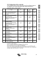
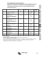
3.5 Configuration of the controller
Fully programmable charge algorithm (see the software page on
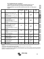
our website) and eight preprogrammed charge algorithms,
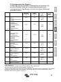
selectable with a rotary switch:
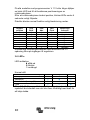
Pos
Suggested battery
Type
Absorption
V
Float
V
Equalize
V
@%I
nom
dV/dT
mV/°C
0
Gel Victron long life (OPzV)
Gel exide A600 (OPzV)
Gel MK
28,2 27,6
31,8
@8%
-32
1
Gel Victron deep discharge
Gel Exide A200
AGM Victron deep discharge
Stationary tubular plate
(OPzS)
28,6 27,6
32,2
@8%
-32
2
Default setting
Gel Victron deep discharge
Gel Exide A200
AGM Victron deep discharge
Stationary tubular plate
(OPzS)
28,8 27,6
32,4
@8%
-32
3
AGM spiral cell
Stationary tubular plate
(OPzS)
Rolls AGM
29,4 27,6
33,0
@8%
-32
4
PzS tubular plate traction
batteries or
OPzS batteries
29,8 27,6
33,4
@25%
-32
5
PzS tubular plate traction
batteries or
OPzS batteries
30,2 27,6
33,8
@25%
-32
6
PzS tubular plate traction
batteries or
OPzS batteries
30,6 27,6
34,2
@25%
-32
7
Lithium Iron Phosphate
(LiFePo
4
) batteries
28,4 27,0 n.a. 0
Note 1: divide all values by two in case of a 12V system and multiply by two
in case of a 48V system.
Note 2: equalize normally off, see sect. 3.8 to activate.
(do not equalize VRLA Gel and AGM batteries)
Note 3: any setting change performed with Bluetooth or via VE.Direct will
override the rotary switch setting. Turning the rotary switch will override prior
settings made with Bluetooth or VE.Direct.

8
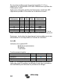
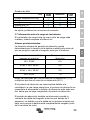
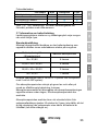
On all models with software version V 1.12 or higher a binary
LED code helps determining the position of the rotary switch.
After changing the position of the rotary switch, the LEDs will
blink during 4 seconds as follows:
Thereafter, normal indication resumes, as described below.
Remark: the blink function is enabled only when PV power is
present on the input of the controller.
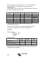
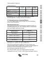
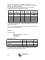
3.6 LEDs
LED indication:
permanent on
blinking
off
Regular operation
LEDs
Bulk
Absorption
Float
Bulk (*1)
Absorption
Automatic equalisation (*2)
Float
Note (*1): The bulk LED will blink briefly every 3 seconds when
the system is powered but there is insufficient power to start
charging.
Fault situations
LEDs
Bulk
Absorption
Float
Charger temperature too high
Charger over-current
Charger over-voltage
Internal error (*3)
Note (*2): E.g. calibration and/or settings data lost, current sensor
issue.
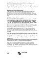
Switch
position
LED
Bulk
LED
Abs
LED
Float
Blink
frequency
0
1
1
1
Fast
1
0
0
1
Slow
2
0
1
0
Slow
3
0
1
1
Slow
4
1
0
0
Slow
5
1
0
1
Slow
6
1
1
0
Slow
7
1
1
1
Slow

9
EN NL FR DE ES SE Appendix
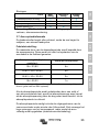
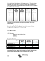
3.7 Battery charging information
The charge controller starts a new charge cycle every morning,
when the sun starts shining.
Default setting:
The maximum duration of the absorption period is determined
by the battery voltage measured just before the solar charger
starts up in the morning:
Battery voltage Vb (@start-up) Maximum absorption time
Vb < 23,8V 6h
23,8V < Vb < 24,4V 4h
24,4V < Vb < 25,2V 2h
Vb > 25,2V 1h
(divide voltages by 2 for a 12V system and multiply by two in
case of a 48V system)
If the absorption period is interrupted due to a cloud or due to a
power hungry load, the absorption process will resume when
absorption voltage is reached again later on the day, until the
absorption period has been completed.
The absorption period also ends when the output current of the
solar charger drops to less than 2Amps, not because of low
solar array output but because the battery is fully charged (tail
current cut off).
This algorithm prevents over charge of the battery due to daily
absorption charging when the system operates without load or
with a small load.
User defined algorithm:
Any setting change performed with Bluetooth or via VE.Direct will
override the rotary switch setting. Turning the rotary switch will
override prior settings made with Bluetooth or VE.Direct.

10
3.8 Automatic equalization
Automatic equalization is default set to ‘OFF’. With the Victron
Connect app (see sect 1.11) this setting can be configured with a
number between 1 (every day) and 250 (once every 250 days).
When automatic equalization is active, the absorption charge will
be followed by a voltage limited constant current period (see table
in section 3.5). The current is limited to 8% of the bulk current for
all VRLA (Gel or AGM) batteries and some flooded batteries, and
to 25% of the bulk current for all tubular plate batteries and the
user defined battery type. The bulk current is the rated charger
current unless a lower maximum current setting has been
chosen.
In case of all VRLA batteries and some flooded batteries
(algorithm number 0, 1, 2 or 3) automatic equalization ends when
the voltage limit maxV has been reached, or after t = (absorption
time)/8, whichever comes first.
For all tubular plate batteries and the user defined battery type
automatic equalization ends after t = (absorption time)/2.
When automatic equalisation is not completely finished within one
day, it will not resume the next day, and the next equalisation
session will take place as determined by the day interval.

11
EN NL FR DE ES SE Appendix
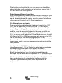
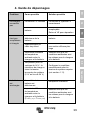
4. Troubleshooting
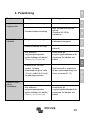
Problem
Possible cause
Solution
Charger does not
function
Reversed PV connection Connect PV correctly
Reverse battery
connection
Non replacable fuse
blown.
Return to VE for repair
The battery is not fully
charged
A bad battery connection
Check battery
connection
Cable losses too high
Use cables with larger
cross section
Large ambient
temperature difference
between charger and
battery (T
ambient_chrg
>
T
ambient_batt
)
Make sure that
ambient conditions
are equal for charger
and battery
Only for a 24V or 48V
system: wrong system
voltage chosen by the
charge controller
Set the controller
manually to the
required system
voltage (see section
1.11)
The battery is being
overcharged
A battery cell is defect
Replace battery
Large ambient
temperature difference
between charger and
battery (T
ambient_chrg
<
T
ambient_batt
)
Make sure that
ambient conditions
are equal for charger
and battery

12
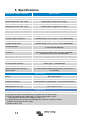
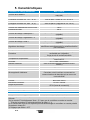
5. Specifications
SmartSolar charge controller MPPT 150/35
Battery voltage
12/24/48V Auto Select (36V: manual)
Maximum battery current
35A
Nominal PV power, 12V 1a,b)
500W (MPPT range 15V to 130V)
Nominal PV power, 24V 1a,b)
1000W (MPPT range 30V to 130V)
Nominal PV power, 48V 1a,b)
2000W (MPPT range 60V to 130V)
Max. PV short circuit current 2)
40A
Maximum PV open circuit voltage
150V
Peak efficiency
98%
Self consumption
10mA
Charge voltage 'absorption'
Default setting: 14,4V / 28,8V / 57,6V (adjustable)
Charge voltage 'equalization' 3)
Default setting: 16,2V / 32,4V / 64,8V (adjustable)
Charge voltage 'float'
Default setting: 13,8V / 27,6V / 55,2V (adjustable)
Charge algorithm
Multi-stage adaptive (eight preprogrammed algorithms)
or user defined algorithm
Temperature compensation
-16mV / -32mV / -68mV / °C
Protection
Battery reverse polarity (fuse, not user accessible)
Output short circuit / Over temperature
Operating temperature
-30 to +60°C (full rated output up to 40°C)
Humidity
95%, non-condensing
Maximum altitude
5000m (full rated output up to 2000m)
Environmental condition
Indoor type 1, unconditioned
Pollution degree
PD3
Data communication port and
remote on/off
VE.Direct (see the data communication white paper on
our website)
ENCLOSURE
Colour
Blue (RAL 5012)
Power terminals
16mm² / AWG6
Protection category
IP43 (electronic components), IP 22 (connection area)
Weight
1,25kg
Dimensions (h x w x d)
130 x 186 x 70 mm
STANDARDS
Safety
EN/IEC 62109-1, UL 1741, CSA C22.2
1a) If more PV power is connected, the controller will limit input power.
1b) The PV voltage must exceed Vbat + 5V for the controller to start.
Thereafter the minimum PV voltage is Vbat + 1V.
2) A higher short circuit current may damage the controller in case of reverse
polarity connection of the PV array.
3) Default setting: OFF

13
EN NL FR DE ES SE Appendix


1
EN NL FR DE ES SE Appendix
1. Algemene beschrijving
1.1 Laadstroom tot 35A en PV-spanning tot 100V
De SmartSolar MPPT 100/35 laadcontroller kan een accu met
een lagere nominale spanning laden vanaf een PV-paneel met
een hogere nominale spanning.
De controller past zich automatisch aan aan een nominale
accuspanning van 12V, 24V of 48V.
1.2 Ultrasnelle Maximum Power Point Tracking (MPPT)
Vooral als het bewolkt is en de lichtintensiteit voortdurend
verandert, verbetert een ultrasnelle MPPT-controller de
energieopbrengst tot 30% in vergelijking met PWM-
laadcontrollers en tot 10% in vergelijking met tragere MPPT-
controllers.
1.3 Advanced Maximum Power Point Detection in het geval
van wisselende schaduw
In het geval van wisselende schaduw kan de vermogen-
spanningscurve twee of meer maximale vermogenspunten
bevatten.
Conventionele MPPT's benutten meestal plaatselijke MPP,
hetgeen mogelijk niet het optimale MPP is.
Het innovatieve SmartSolar-algoritme maximaliseert de
energieopbrengst altijd door het optimale MPP te benutten.
1.4 Uitstekend omzettingsrendement
Geen koelventilator. Het maximale rendement bedraagt meer
dan 98%. Volledige uitgangsstroom tot 40°C (104°F).
1.5 Uitgebreide elektronische beveiliging
Beveiliging tegen overtemperatuur en vermogensvermindering
bij hoge temperaturen.
Beveiliging tegen PV-kortsluiting en omgekeerde PV-polariteit.
Beveiliging tegen PV-sperstroom.

2
1.6 Interne temperatuursensor
Compenseert absorptie- en druppelladingsspanningen voor
temperatuur.
1.7 Automatische herkenning van de accuspanning
De controller past zich slechts een keer automatisch aan aan
een 12V-, 24V- of een 48V-systeem. Als op een later moment
een andere systeemspanning is vereist, moet deze handmatig
worden gewijzigd, bijvoorbeeld met de Bluetooth-app, zie
paragraaf 1.11.
1.8 Flexibel laadalgoritme
Volledig programmeerbaar laadalgoritme en acht
voorgeprogrammeerde algoritmes die met een draaischakelaar
gekozen kunnen worden.
1.9 Adaptief drietraps laden
De SmarSolar MPPT-laadcontroller is geconfigureerd voor een
drietraps oplaadproces: Bulklading, absorptielading en
druppellading.
1.9.1. Bulklading
Tijdens deze fase levert de controller zoveel mogelijk laadstroom
om de accu's snel op te laden.
1.9.2. Absorptielading
Als de accuspanning de ingestelde absorptiespanning bereikt,
schakelt de controller over op de constante spanningsmodus.
Als enkel lichte ontladingen optreden, wordt de absorptietijd kort
gehouden om overlading van de accu te voorkomen. Na een
diepe ontlading wordt de absorptietijd automatisch verhoogd om
ervoor te zorgen dat de accu opnieuw volledig wordt geladen.
Daarnaast wordt de absorptietijd ook beëindigd als de laadstroom
onder 2A daalt.
1.9.3. Druppellading
Tijdens deze fase wordt de druppelladingsspanning toegepast op
de accu om deze volledig opgeladen te houden.
Wanneer de accuspanning minimaal 1 minuut onder de
druppelladingsspanning daalt, wordt een nieuwe laadcyclus
geactiveerd.
1.9.4. Egalisatie
Zie hoofdstuk 3.8.

3
EN NL FR DE ES SE Appendix
1.10 Aan/uit op afstand
De MPPT 150/35 kan op afstand worden bestuurd door een
VE.Direct niet-omvormende kabel voor het op afstand in- of
uitschakelen (ASS030550300). De ingang HIGH (Vi > 8V)
schakelt de controller in en de ingang LOW (V < 2V, of ‘free
floating’) schakelt de controller uit.
Toepassingsvoorbeeld: in-/uitschakelen op afstand door een
VE.Bus BMS voor het opladen van lithium-ionaccu's.
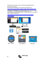
1.11 Configuratie en bewaking
- Bluetooth Smart ingebouwd: De draadloze oplossing om de
controller in te stellen, te bewaken en te updaten via Apple- of
Android-smartphones, -tablets of andere apparaten.
- Gebruik de VE.Direct naar USB-kabel (ASS030530000) om
verbinding te maken met een pc, een smartphone met Android
en USB On-The-Go support (extra USB OTG-kabel vereist).
- Gebruik een VE.Direct naar VE.Direct-kabel om verbinding te
maken met een MPPT Control, een Color Control of de Venus
GX.

4
Meerdere parameters kunnen worden aangepast met de
VictronConnect-app.
De VictronConnect-app kan worden gedownload op
http://www.victronenergy.nl/support-and-downloads/software/
Gebruik de handleiding - VictronConnect - MPPT Solar Charge
Controllers - om optimaal gebruik te maken van de
VictronConnect App wanneer deze verbonden is met een MPPT
Solar Charge Controller:
http://www.victronenergy.com/live/victronconnect:mppt-
solarchargers
MPPT Control
Color Control
Venus GX
La page est en cours de chargement...
La page est en cours de chargement...
La page est en cours de chargement...
La page est en cours de chargement...
La page est en cours de chargement...
La page est en cours de chargement...
La page est en cours de chargement...
La page est en cours de chargement...
La page est en cours de chargement...
La page est en cours de chargement...
La page est en cours de chargement...
La page est en cours de chargement...
La page est en cours de chargement...
La page est en cours de chargement...
La page est en cours de chargement...
La page est en cours de chargement...
La page est en cours de chargement...
La page est en cours de chargement...
La page est en cours de chargement...
La page est en cours de chargement...
La page est en cours de chargement...
La page est en cours de chargement...
La page est en cours de chargement...
La page est en cours de chargement...
La page est en cours de chargement...
La page est en cours de chargement...
La page est en cours de chargement...
La page est en cours de chargement...
La page est en cours de chargement...
La page est en cours de chargement...
La page est en cours de chargement...
La page est en cours de chargement...
La page est en cours de chargement...
La page est en cours de chargement...
La page est en cours de chargement...
La page est en cours de chargement...
La page est en cours de chargement...
La page est en cours de chargement...
La page est en cours de chargement...
La page est en cours de chargement...
La page est en cours de chargement...
La page est en cours de chargement...
La page est en cours de chargement...
La page est en cours de chargement...
La page est en cours de chargement...
La page est en cours de chargement...
La page est en cours de chargement...
La page est en cours de chargement...
La page est en cours de chargement...
La page est en cours de chargement...
La page est en cours de chargement...
La page est en cours de chargement...
La page est en cours de chargement...
La page est en cours de chargement...
La page est en cours de chargement...
La page est en cours de chargement...
La page est en cours de chargement...
La page est en cours de chargement...
La page est en cours de chargement...
La page est en cours de chargement...
La page est en cours de chargement...
La page est en cours de chargement...
La page est en cours de chargement...
La page est en cours de chargement...
La page est en cours de chargement...
La page est en cours de chargement...
La page est en cours de chargement...
La page est en cours de chargement...
La page est en cours de chargement...
-
 1
1
-
 2
2
-
 3
3
-
 4
4
-
 5
5
-
 6
6
-
 7
7
-
 8
8
-
 9
9
-
 10
10
-
 11
11
-
 12
12
-
 13
13
-
 14
14
-
 15
15
-
 16
16
-
 17
17
-
 18
18
-
 19
19
-
 20
20
-
 21
21
-
 22
22
-
 23
23
-
 24
24
-
 25
25
-
 26
26
-
 27
27
-
 28
28
-
 29
29
-
 30
30
-
 31
31
-
 32
32
-
 33
33
-
 34
34
-
 35
35
-
 36
36
-
 37
37
-
 38
38
-
 39
39
-
 40
40
-
 41
41
-
 42
42
-
 43
43
-
 44
44
-
 45
45
-
 46
46
-
 47
47
-
 48
48
-
 49
49
-
 50
50
-
 51
51
-
 52
52
-
 53
53
-
 54
54
-
 55
55
-
 56
56
-
 57
57
-
 58
58
-
 59
59
-
 60
60
-
 61
61
-
 62
62
-
 63
63
-
 64
64
-
 65
65
-
 66
66
-
 67
67
-
 68
68
-
 69
69
-
 70
70
-
 71
71
-
 72
72
-
 73
73
-
 74
74
-
 75
75
-
 76
76
-
 77
77
-
 78
78
-
 79
79
-
 80
80
-
 81
81
-
 82
82
-
 83
83
-
 84
84
-
 85
85
-
 86
86
-
 87
87
-
 88
88
-
 89
89


Victron energy SmartSolar MPPT 150/35 Le manuel du propriétaire
- Taper
- Le manuel du propriétaire
dans d''autres langues
Documents connexes
-
Victron energy BlueSolar MPPT 100/30 Le manuel du propriétaire
-
-
-
-
-
-
-
-
-