Morningstar GFPD-150V Manuel utilisateur
- Taper
- Manuel utilisateur

www.morningstarcorp.com
MORNINGSTAR
World’s Leading Solar Controllers & Inver ters
For the most recent manual updates, please visit our website.
InstallatIon and operatIon Manual
GROUND-FAULT
PROTECTION DEVICE
150V MODEL

ii 1
TABLE OF CONTENTS
1.0 Important Safety Instructions.............................. 1
2.0 Dimensions and Features...................................... 7
3.0 Installation.................................................................. 8
3.1.0 Mounting the GFPD-150V Box................... 8
3.1.1 Paired to a Tristar.................................... 8
3.1.2 Coupling..................................................... 9
3.1.3 Vertical Mounting.................................... 9
3.1.4 Stand-Alone Use.......................................10
3.2.0 Wiring the GFPD-150V Box.........................10
3.2.1 Pre-Wired GFPD-150V / Breaker
Assembly...................................................10
3.2.2 Completing Wiring..................................11
4.0 GFPD-150V Operation...........................................14
4.1 Ground-Fault Detection...................................14
4.2 LED Indications and Audible Warnings......14
4.3 Test Button Uses................................................14
5.0 Troubleshooting........................................................16
5.1 Faults and Corrections.....................................16
6.0 Warranty......................................................................18
7.0 Technical Specifications..........................................19
8.0 Certifications................................................ 21
1.0 IMPORTANT SAFETY INSTRUCTIONS
SAVE THESE INSTRUCTIONS.
This manual contains important safety instructions for
the GFPD-150V. The instructions shall be followed
during installation, operation and maintenance of the
Ground-Fault Protection Device. The following sym-
bols are used throughout this manual to indicate
potentially dangerous conditions or important safety
instructions.
CONSERVER CES INSTRUCTIONS.
Ce manuel contient des instructions de sécurité impor-
tantes pour le GFPD-150V. Les instructions doivent
être suivies pendant l'installation, exploitation et
entretien de l'appareil de Protection de fuite à la terre.
Les symboles suivants sont utilisés tout au long de ce
manuel pour indiquer des conditions potentiellement
dangereuses ou des consignes de sécurité impor-
tantes.
WARNING: Indicates a potentially dangerous
condition. Use extreme caution when performing this
task.
CAUTION: Indicates a critical procedure for safe and
proper operation of the GFPD-150V.
NOTE: Indicates a procedure or function that is
important for the safe and proper operation of the
GFPD-150V.
AVERTISSEMENT: Indique une condition
potentiellement dangereuse. Faites preuve d’une
prudence extrême lors de la réalisation de cette
tâche.
PRUDENCE: Indique une procédure critique pour
l’utilisation sûre et correcte du GFPD-150V.

2 3
REMARQUE: Indique une procédure ou fonction
importante pour l’utilisation sûre et correcte du GFPD-
150V.
WARNING: A battery can present a risk of electrical
shock or burn from large amounts of short-circuit
current, fire, or explosion from vented gases.
Observe proper precautions.
CAUTION: When replacing batteries, use properly
specified sizes, types, and ratings based on
application and system design.
CAUTION: Proper disposal of batteries is required.
refer to local regulations or codes for requirements.
AVERTISSEMENT: Une batterie peut présenter a
risque de choc électrique ou de brûlure de grandes
quantités de court-circuit curlouer, incendie ou explo-
sion de ventilé gaz.
PRUDENCE: Observer les précautions adéquates.
Quand remplacer l'utilisation de piles correctement
spécifié tailles, types, et cotes fondées sur l'application
et conception des systèmes.
PRUDENCE: Élimination appropriée des batpiles
est nécessaire. Se ré férer au local règlements ou
codes pour exigentments.
NOTE: The GFPD-150V must be used with
grounded systems, and will interrupt ground-fault
current by disconnecting the positive and negative
PV conductors, and not the earth ground
conductor. Properly grounded batteries will
always maintain any earth bond even in ground-
fault conditions.
REMARQUE: Le DPDT-150V doit être utilisé avec
mise à la terre des systèmes et interrompt la fuite à
la terre courant en débranchant le positif et négatif
Conducteurs de PV et pas la mise à la terre
chef d’orchestre. Les piles correctement mise à la
terre sera toujours maintenir une liaison à la terre
même en sol fonctionnement anormal.
Lisez toutes les instructions et les avertissements figu-
rant dans le manuel avant de commencer l’installation.
♦ Le GFPD-150V ne contient aucune pièce réparable
par l’utilisateur. Ne démontez pas ni ne tentez de
réparer le appareil.
♦ Déconnectez toutes les sources d’alimentation du
contrôleur avant d’installer ou de régler le
GFPD-150V.
♦ Le GFS-1 (unité de détection) ne contient aucun
fusible ou interrupteur. Ne tentez pas de réparer.
♦ Installation circuit externe se déconnecte au besoin.
WARNING: To reduce the risk of electrical shock,
do not perform any service other than that
specified in the operating instructions, unless you
are qualified to do so.
AVERTISSEMENT: Pour réduire le risque de choc
électrique, n'effectuez aucune opération
d'entretien autre que celui spécifié dans la notice
d'utilisation, sauf si vous êtes qualifié pour cela.
Read all of the instructions and cautions in the manual
before beginning installation.
♦ There are no user serviceable parts inside the GFPD-
150V. Do not disassemble or attempt to repair the
device.
♦ Disconnect all sources of power to the device before
installing or adjusting the GFPD-150V.
♦ There are no fuses or disconnects inside the GFS-1
(sensing unit). Do not attempt to repair.
♦ Install external circuit disconnects as required.
Safety Information
Informations de Sécurité

4 5
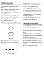
♦ The grounding terminal lug is located in the wiring
compartment and is identified by the symbol below:
Ground Symbol
♦ The GFPD-150V is to be connected in DC circuits
only. These DC connections are identified by the
symbol below:
Direct Current Symbol
Installation Safety Precautions
♦ Mount the GFPD-150V indoors. Prevent exposure
to the elements and do not allow water to enter the
device.
♦ Use insulated tools when working with batteries.
♦ Avoid wearing jewelry during installation.
♦ The battery bank must be comprised of batteries of
same type, make, and age.
♦ Do not smoke in the vicinity of the battery bank.
♦ Power connections must remain tight to avoid ex-
cessive heating from a loose connection.
♦ Use properly sized conductors.
Précautions de Sécurité D'installation
♦ Mont le GFPD-150V à l'intérieur. Éviter l'exposition
aux intempéries et ne permettent pas de l'eau
d'entrer dans le périphérique.
♦ Utiliser des outils isolés lorsque vous travaillez avec
des piles.
♦ Éviter de porter des bijoux lors de l'installation.
♦ La Banque de batterie doit être composée de piles
de même type, marque et l'âge.
♦ Ne pas fumer à proximité de la Banque de batterie.
♦ Connexions d'alimentation doivent rester serrées
pour éviter un échauffement excessif d'une mauvaise
connexion.
♦ Utilisez la bonne taille des conducteurs.
The GFPD-150V must be installed by a qualified
technician in accordance with electrical regulations of
the country where the product is installed.
Using the GFPD-150V grounding terminal lug (in
the wiring compartment), a permanent and reliable
conductor to the earth ground must be established.
The grounding conductor must be secured against
any accidental detatchment.
The knock-outs in GFPD-150V wiring compartment
must protect wires with conduit or rings.

6 7
♦ La cosse de mise à la terre se trouve dans le
compartiment de câblage et est identifiée par le
symbole ci-dessous:
Symbole de la terre
♦ Le GFPD-150V doit être raccordé dans les circuits en
courant continu. Ces connexions DC sont identifiées
par le symbole ci-dessous:
Symbole courant continu
♦
Le GFPD-150V doit être installé par un technicien
qualifié conformément à la réglementation électrique
du pays où le produit est installé.
♦
À l'aide de la cosse de terre (dans le compartiment
de câblage) GFPD-150V, chef d'orchestre permanent et
fiable pour la prise de terre doit être établi.
♦
Le conducteur de terre doit être protégée contre tout
détachement accidentel.
♦
L'apport défonçables dans compartiment de câblage
GFPD-150V doivent être protégés avec conduit ou
anneaux.
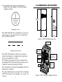
Figure 1. GFPD-150V Box Dimensions
Figure 2. GFPD-150V Box and Major Features
2.0 DIMENSIONS AND FEATURES
10.60 in.
[ 269 mm ]
5.02 in.
[ 128 mm ]
4.39 in.
[ 112 mm]
Four Power
Termination
Posts (underside)
Conduit / Wire
Knock-Outs
Equipment
Ground
Terminations
Wiring
Aperture
Case
Test / Reset
Button
Breakers
Bi-color LED -
red and green

8 9
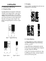
3.0 INSTALLATION
8
3.1.0 Mounting the GFPD-150V Box
3.1.1 Paired to a TriStar
The GFPD-150V box can be paired with a Morningstar
150V MPPT TriStar charge controller in several ways. A
suggested mounting configuration is with the GFPD-
150V box to the left of the vertically mounted controller
with the two small knock-outs and one large knock-out
from each unit lining up as shown in Figure 3. Two
optional mounting configurations are shown in Figures
4 and 5.
Figure 4. Option 1
Figure 3. Suggested Mounting
Figure 5. Option 2
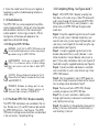
3.1.2 Coupling
3.1.3 Vertical Mounting
1. If TriStar controller has not been installed, refer to
TriStar MPPT-150V operator's manual for mounting
instructions, and install.
2. Align GFPD-150 box in desired position and mark
the four (4) corner mounting hole locations through the
wiring box.
Remove the GFPD box.
3. Drill 3/32” (2.5 mm) holes at the drill marks. Align
the GFPD box over the holes, and
secure the device
with four (4) #10 mounting screws.
Coupling hardware is provided for joining the two cases
using knock-outs as shown below:

10 11
3.2.0 Wiring the GFPD-150V Box
WARNING: Verify that the GFPD-150V breakers and
the solar and battery disconnect switches (required) are
open before wiring the GFPD-150V Box.
CAUTION: Wiring methods must conform to the U.S.
National Electrical Code or Canandian Electrical Code
and ANSI/NFPA 70.
AVERTISSEMENT : Vérifiez que les attaquants GFPD-
150V et les sectionneurs solaires et batterie (obliga-
toire) sont ouvertes avant de câbler la boîte GFPD-
150V.
PRUDENCE: Méthodes de câblage doit être con-
forme au Code électrique National américain ou
Canandian Code électrique et ANSI/NFPA 70.
3.2.1 Pre-Wired GFPD-150V / Breaker Assembly
The GFPD-150V and breakers are assembled at the fac-
tory. Breaker shunt, (C) and (NO) leads are pre-wired to
the GFPD-150V terminals - See Figure 6. The GFPD-
150V external voltage source connections are described
in the next section - Completing Wiring.
3.2.2 Completing Wiring - See Figures 6 and 74. Fasten the mated faces of the two units together at
two places using the included coupling hardware as
shown above.
3.1.4 Stand-Alone Use
The GFPD-150V can also be coupled with non-Morn-
ingstar charge controllers. Wiring will mirror the proce-
dure described in Section 3.2.2, but connecting to
another product’s terminal lugs instead of a TriStar’s.
Configuration of the boxes will depend on the
application and controller design.
Step 1. With GFPD-150V / breaker assembly free
from box, run the solar array (+) (from PV disconnect)
and (-) wires through left knock-out and GFPD-150V
Wiring Aperture. Run the (+) and (-) breaker<-> con-
troller wires into GFPD-150V box through mated
knock-outs.
Step 2. Crimp the supplied ring terminals on the ends
of the (+) and (-) solar<->breaker conductors, and
connect solar array (+) wire to post (4) (load side), and
solar array (-) wire to post (2) (line side) using the sup-
plied hardware (see Figure 6).
Step 3. Crimp the supplied ring terminals on the
breaker side ends of the (+) and (-) breaker <->con-
troller conductors. Connect breaker side (+) wire to
post (1) (line side), and breaker side (-) wire to post (3)
(load side) using the supplied hardware (see Figure 6).
Step 4. Connect controller side breaker<->controller
wires to controller (+) and (-) solar terminal lugs. Close
GFPD-150V breakers.
Step 5. Run the supplied (+) and (-) GFPD power ter-
minal wires through a convenient knock-out for connec-
tion to voltage source described in Step 9.
Step 6. Position and fasten GFPD-150V / Breaker
assembly into place in the GFPD-150V box.
Step 7. Run (+) and (-) controller<->battery wires
through right knock-out, and connect to controller’s (+)
and (-) battery terminal lugs.
Step 8. Wire battery (+) through battery disconnect to
battery (+) terminal, and connect. Connect battery (-)
wire to battery (-) terminal.

12 13
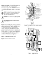
Figure 6. Pre-Wired GFPD-150V / Breaker Assembly
Figure 7. Completing Wiring
Power Posts 1-4
3
4
2
1
Trip Signal Wire (typ. of
2). Terminated with
insulated 600V 10-32
ring terminal (typ. of 2)
Power
Terminals
Feedback Signal / C
and NO Wires - no
polarity. Connected
to labeled breaker
assembly blades.
Not for use - no
connection should
be made here
Insulated 600V 0.11in. female
quick disconnect (typ. of 2)
Shunt Post
Load Side
Line Side
Shunt Post
PV (+)
TERMINAL
LUG
3
4
2
1
PV INPUTS
BATTERY (+)
TERMINAL
LUG
(+)
(+)
(-)
(-)
(-)
TO
BATTERY
COMMON
TERMINAL
LUGS
TIE CASE and
OTHER DEAD
METAL to EARTH
GROUND
(-)
(+)
Step 9. Using supplied in-line fuse holder and 5A fuse,
install fuse 6 to 12 in. from (+) battery terminal.
Connect (+) and (-) wires from GFPD-150V to external
10-72V source (usually system battery) (+) and (-) termi-
nals.
NOTE: Do not tap from a lower voltage battery
bank section that is part of a higher voltage
bank. An imbalance will occur.
WARNING: The PV system must be properly grounded
AVERTISSEMENT: Le système PV doit être correcte-
ment mise à la terre.
Step 10. Ground the PV system properly by electrically
connecting each individual metallic component such as
PV frames, conduit, combiner boxes, controllers,
inverters, GFDIs, and any other dead metal to Earth
ground. Locate the system ground on the battery side
at either a battery (+) or battery (-) terminal depending
on system polarity. Install the grounding system in
accordance with local codes and regulations.
Step 11. Close battery disconnect switch.
Step 12. Close solar disconnect switch.

14 1514
4.0 GFPD-150V OPERATION
4.1 Ground-Fault Detection
4.2 LED Indications and Audible Warnings
Ground-fault protection is used in electrical systems to
prevent current from following any unintended paths. It
is critical to detect any stray current, and to interrupt
(break) the circuit until safe operation can be restored.
Any current imbalance between the (+) and (-) conduc-
tors of a circuit indicates a ground-fault. Morningstar’s
GFPD-150V will detect this condition, and break the
circuit on both the (+) and (-) legs, ensuring interruption.
A bi-color LED and buzzer indicate operating status, a
ground-fault event, module/wiring faults and low battery
voltage.
GFPD-150V Condition LED / Buzzer Indication
Start-up Three green flashes
Normal Solid green
Ground-fault Detected or
Ground-fault Trip
Solid red + buzzer (3 sec.
beep / min.)
Ground-fault Error Red flashing + buzzer
Wiring Error or Open
Breaker Alarm
Red / green flashing
Low Battery Voltage
Threshold Reached
Buzzer (beep 3x / min.)
Critical Fault Red / red / green / green
4.3 Test Button Uses
The test button can be used for three purposes:
1. With the GFPD-150V in normal mode, pressing the
test button conducts a system test that opens the
breaker, shows a red solid LED, and sounds the buzzer.
2. When a ground-fault error has occurred, pressing the
test button resets the GFPD-150V to the normal
condition.
3. When a wiring error / open breaker alarm has
occurred, pressing the test button resets the GFPD-150V
to the normal condition.

16 17
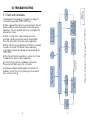
Figure 8. Diagnostic Flow Diagram Conditions
NORMAL
(LED SOLID GREEN)
WIRING ERROR or
OPEN BREAKER
ALARM (LED RED /
GREEN FLASHING)
GF DETECTED or GF
TRIP (LED RED SOLID +
BUZZER)
GF ERROR (LED RED
FLASHING + BUZZER)
LOW
BATTERY
BUZZER
TEST BUTTON
PRESSED
TEST BUTTON
PRESSED
START-UP SEQUENCE (LED
THREE GREEN FLASHES)
TEST BUTTON
PRESSED (System
Test)
GROUND
FAULT
CLOSE
BREAKER
MANUALLY
NOTE: IF GF CURRENT
STILL PRESENT OR
BREAKER OPEN
SYMBOLS:
/ Sequencing
+ Simultaneous
CRITICAL FAULT (LED
RED / RED / GREEN /
GREEN FLASHING)
5.0 TROUBLESHOOTING
5.1 Faults and Corrections
The diagnostic flow diagram in Figure 8 on page 17
illustrates the possible GFPD-150V faults.
♦ When a ground-fault error has occurred, push the test
button and then close the breaker to resume normal
operation. Have a qualified technician investigate the
ground-fault cause.
♦ When a wiring error / open breaker alarm has
occurred, correct wiring error and/or close breaker.
Push the test button to resume normal operation.
♦ When the minimum requirement of 9 Volts is reached,
a buzzer will sound. To resume normal operation,
re-charge or replace the voltage source powering the
GFPD-150V.
♦ Push the test button to perform a system test. Close
the breaker to resume normal operation.
♦ A critical fault indicates a hardware malfunction.
Please contact Morningstar for instructions.
♦ If previous trouble-shooting does not correct the
problem, re-start the unit by removing in-line source
fuse, and re-installing.

18 19
6.0 WARRANTY
LIMITED WARRANTY Morningstar Solar Controllers and Inverters
The GFPD-150V is warrantied to be free from defects in materials and
workmanship for a period of FIVE (5) years from the date of shipment to the
original end user. Morningstar will, at its option, repair or replace any such
defective products.
CLAIMS PROCEDURE
Before requesting warranty service, check the Operator’s Manual
to be certain that there is a problem with the controller. Return
the defective product to your authorized Morningstar distributor
with shipping charges prepaid. Provide proof of date and place of
purchase.
To obtain service under this warranty, the returned products must
include the model, serial number, detailed reason for the failure, the
module type, array size, type of batteries and system loads. This
information is critical to a rapid response to your warranty claim.
Morningstar will pay the return shipping charges if the repairs are
covered under the warranty.
WARRANTY EXCLUSIONS AND LIMITATIONS:
This warranty does not apply under the following conditions:
♦ Damage by accident, negligence, abuse or improper use
♦ PV or load currents exceeding the ratings of the product
♦ Unauthorized product modification or attempted repair
♦ Damage occurring during shipment
♦ Damage results from acts of nature such as lightning and weather extremes
THE WARRANTY AND REMEDIES SET FORTH ABOVE ARE EXCLUSIVE AND IN
LIEU OF ALL OTHERS, EXPRESS OR IMPLIED. MORNINGSTAR SPECIFICALLY
DISCLAIMS ANY AND ALL IMPLIED WARRANTIES, INCLUDING, WITHOUT
LIMITATION, WARRANTIES OF MERCHANTABILITY AND FITNESS FOR A
PARTICULAR PURPOSE. NO MORNINGSTAR DISTRIBUTOR, AGENT OR
EMPLOYEE IS AUTHORIZED TO MAKE ANY MODIFICATION OR EXTENSION
TO THIS WARRANTY.
MORNINGSTAR IS NOT RESPONSIBLE FOR INCIDENTAL OR
CONSEQUENTIAL DAMAGES OF ANY KIND, INCLUDING BUT NOT LIMITED
TO LOST PROFITS, DOWN-TIME, GOODWILL OR DAMAGE TO EQUIPMENT
OR PROPERTY.
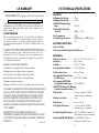
7.0 TECHNICAL SPECIFICATIONS
ELECTRICAL:
♦ Maximum Solar Voltage................150 vdc
♦ Maximum Solar Current................ 85 adc
♦ GFPD-150V Supply Voltage
Range ............................................. 10-72 vdc
♦ Ground-Fault Current Trip
Threshold....................................... 300mA +/- 10%
♦ Self-consumption ........................... <1W
♦ Transient Surge Protection ........... 3000W Battery and 1500W Signal
Port
ELECTRONIC PROTECTIONS:
♦ Reverse Polarity
♦ Disconnected Feedback Signal Circuit Detection
MECHANICAL:
♦ Dimensions (in/cm)....................... 10.6 x 5.1 x 4.4 / 26.8 x 12.8 x 11.2
♦ Enclosure.......................................Type 1 Indoors
♦ Weight........................................... 4.39 lbs / 1.99 kgs
♦ Sensing Aperture Diameter..........0.79 in. (20.0 mm)
♦ Breaker Power Posts....................1/4 in. - 20 Studs
♦ Recommended Breaker Power
Post Nut Torque
............................30-35 in-lb (3.4-4 Nm)
♦ Recommended GFPD-150V
Sensing Unit Terminal Torque....
...3.5 in-lb (0.4 Nm)
♦ GFPD-150V Sensing Unit - Minimum
Conductor Temperature Rating....75°C
♦ Battery Wire..................................33 ft. two-conductor 18 AWG -
stranded copper or aluminum
♦ Battery Fuse Holder.......................In-line
♦ Battery Fuse....................................5A, min. 125 vdc
♦ Trip Signal Wire Harness................6 in. two-conductor 18 AWG
stranded copper or aluminum
♦ Feedback Signal Wire Harness......4.5 / 6.5 in. 600V two-conductor 14
AWG stranded copper or aluminum
♦ Mounting (GFPD-150V Module)....35 mm DIN Rail or Panel
Mount with (2)-#6-32 screws
R18-12/16

20 21
7.0 TECHNICAL SPECIFICATIONS (Cont.)
ENVIRONMENTAL:
♦ Operating Temperature Range.....-40°C to +50°C
♦ Storage Temperature Range ........ -55°C to +85°C
♦ Humidity Tolerance.........................Up to 100%
♦ Tropicalization ................................ PCB Conformal Coating
MS-001125 v1.5
©2017 Morningstar Corporation
8.0 CERTIFICATIONS
♦ Meets U.S. NEC 690.5 requirements for use as a
GFDI / GFPD
♦ ETL Listed to UL 1741 and CSA C22.2
No. 107.1-01
♦ EMC Directives Immunity, Emmissions, Safety
♦ FCC Class B Part 15
♦ CE
♦ RoHS
♦ ISO 9000
-
 1
1
-
 2
2
-
 3
3
-
 4
4
-
 5
5
-
 6
6
-
 7
7
-
 8
8
-
 9
9
-
 10
10
-
 11
11
-
 12
12


Morningstar GFPD-150V Manuel utilisateur
- Taper
- Manuel utilisateur
dans d''autres langues
- English: Morningstar GFPD-150V User manual
Documents connexes
-
Morningstar TS-MPPT 150V Manuel utilisateur
-
-
Morningstar Tristar MPPT Solar Charging System Controller Manuel utilisateur
-
Morningstar TS-MPPT 600V Manuel utilisateur
-
-
-
Autres documents
-
Victron energy SmartSolar MPPT 150/35 Le manuel du propriétaire
-
-
-
-