
Solar Charging System Controller
Installation, Operation and
Maintenance Manual
MAXIMUM POWER POINT TRACKING
.....
Solar Battery Charging
.....
Load Control
.....
Diversion Control
TM
For the most recent manual revisions, see the version at:
www.morningstarcorp.com
MODELS
TS-45
TS-60
TS-60M
www.morningstarcorp.com
TM

i MORNINGSTAR CORPORATION
Table of Contents
Important Safety Instructions ................................................................... 1
1.0 TriStar Description ........................................................................... 7
1.1 Versions and Ratings
.....................................................................7
1.2 Operating Modes
....................................................................... 7
1.3 Adjustability
............................................................................... 8
1.4 General Use
............................................................................. 8
1.5 Safety and Regulatory Information
............................................ 10
1.6 Optional Accessories........................................................................
11
2.0 Installation ..............................................................
..............................
12
2.1 General Information
.................................................................... 12
2.2 Installation Overview
................................................................ 13
2.3 Installation Steps
..................................................................... 14
1. Remove the Cover
................................................................ 15
2. Mounting
.................................................................. .............. 15
3. Adjust DIP Switches
.............................................................. 16
4. Remote Temperature Sensor
................................................. 21
5. Battery Voltage Sense
............................................................. 22
6. System Wiring and Power-up
................................................. 23
7. RS-232 Adjustments
.............................................................. 26
8. Finish Installation
................................................................... 26
3.0 Operation ........................................................................................ 27
3.1 Operator’s Tasks
........................................................................ 27
3.2 Push-button......................................................................................
27
3.3 LED Indications
......................................................................... 28
3.4 Protections and Fault Recovery
................................................. 29
3.5 Data-Logging
............................................................................. 32
3.6 Inspection and Maintenance
...................................................... 32
4.0 Solar Battery Charging................................................................. 34
4.1 PWM Battery Charging
................................................................ 34
4.1.1 Four Stages of Solar Charging.........................................34
4.1.2 Battery Charging Notes.................................................... 34
4.2 Standard Battery Charging Programs
........ ................................. 35
4.3 Temperature Effects & Battery Voltage Sense
................................ 36
4.3.1 Remote Temperature Sensor (RTS)................................36
4.3.2 Battery Voltage Sense......................................................37
4.4 Equalization.......................................................................................
38
4.4.1 Standard Equalization Programs......................................39
4.4.2 Typical qualizations...........................................................39
4.4.3 Preparation for equalization..............................................40
4.4.4 When to Equalize..............................................................40
4.4.5 Equalize a Sealed Battery?..............................................40
4.5 Float..................................................................................................41
(continued)
This page inside front
COVER 2
(Please do not print this copy)

1 MORNINGSTAR CORPORATIONii TABLE OF CONTENTS
5.0 Load & Lighting Control ............................................................... 42
5.1 General Load & Lighting Control Notes
............................................42
5.1.1 Inductive Loads.............................................................42
5.1.2 Parallel TriStars....................................................................42
5.1.3 Reverse Polarity...................................................................42
5.2 Load Control Settings
.................................................................. 42
5.3 LVD Warning
..................................................................................44
6.0 Diversion Charge Control
....................................................................
44
6.1 Diversion Charge Control...................
.......................................... 44
6.2 Diversion Current Ratings
.......................................................... 45
6.3 Standard Diversion Battery Charging Programs
.......................... 45
6.3.1 Battery Charging References......................................46
6.4 Selecting the Diversion Load
...............................................................
47
6.4.1 Suitable Loads for Diversion...
............................... .........
.47
6.4.2 Defintion of Terms........................................................47
6.4.3 Load Power Ratings.....................................................48
6.4.4 Maximum Diversion Load............................................48
6.4.5 Minimum Diversion Load.............................................49
6.5 NEC Requirements
.................................................................... 50
6.5.1 Second Independent Means.......................................50
6.5.2 150 Percent Rating..................................................... 50
6.6 Additional Information.....
..............................................................50
7.0 Custom Settings with PC Software...........................................51
7.1 Connection to a Computer
............................................................51
7.2 Using the PC Software
.................................................................51
7.3 Changing Set-points
.....................................................................52
7.4 Finish
...........................................................................................52
8.0 Self-Test / Diagnostics.........................................................................53
8.1 General Troublshooting..............................................................53
8.2 Troubleshooting Solar Charging................................................ 54
8.3 Troubleshooting Load Control................................................... 54
8.4 Troubleshooting Diversion Control.................................. ..........54
9.0 Battery Information (reference).......................................................... 55
9.1 Sealed Batterie
s...........................................................................55
9.2 Flooded Batteries
....................................................................... 56
9.3 L-16 Cells
.................................................................................. 57
10.0 Warranty...............................................................................................58
11.0 Specifications...................................................................................... 59
Appendix 1 - Load and Lighting Control DIP Switch Settings ......................61
Appendix 2 - Diversion Charge Control DIP SwitchSettings........................66
Appendix 3 - LED Indications........................................................................ 70
12.0 Certifications...................................................................................... 73
continued...
IMPORTANT SAFETY INSTRUCTIONS
SAVE THESE INSTRUCTIONS.
This manual contains important safety, installation, operating and mantenance
instructions for the TriStar-PWM solar controller.
The following symbols are used throughout this manual to indicate potentially
dangerous conditions or mark important safety instructions:
WARNING: Indicates a potentially dangerous condition. Use extreme caution
when performing this task.
CAUTION: Indicates a critical procedure for safe and proper operation of the
controller.
NOTE: Indicates a procedure or function that is important to the safe and
proper operation of the controller.
CONSIGNES IMPORTANTES DE SÉCURITÉ
CONSERVEZ CES INSTRUCTIONS.
Ce manuel contient des instructions importantes de sécurité, d’installations et
d’utilisation du contrôleur solaire. TriStar-PWM. Les symboles suivants sont utilisés
dans ce manuel pour indiquer des conditions potentiellement dangereuses ou des
consignes importantes de sécurité.
AVERTISSEMENT: Indique une condition potentiellement dangereuse. Faites
preuve d’une prudence extrême lors de la réalisation de cette tâche.
PRUDENCE: Indique une procédure critique pour l’utilisation sûre et correcte
du contrôleur.
REMARQUE: Indique une procédure ou fonction importante pour l’utilisation
sûre et correcte du contrôleur.
Safety Information
• Read all of the instructions and cautions in the manual before beginning
installation.
• There are no user serviceable parts inside the TriStar-PWM. Do not
disassemble or attempt to repair the controller.

3 MORNINGSTAR CORPORATION2
IMPORTANT SAFETY INSTRUCTIONS
WARNING: RISK OF ELECTRICAL SHOCK.
NO POWER OR ACCESSORY TERMINALS ARE ELECTRICALLY
ISOLATED FROM DC INPUT, AND MAY BE ENERGIZED WITH HAZARD-
OUS SOLAR VOLTAGE. UNDER CERTAIN FAULT CONDITIONS, BATTERY
COULD BECOME OVER-CHARGED. TEST BETWEEN ALL TERMINALS AND
GROUND BEFORE TOUCHING.
• External solar and battery disconnects are required.
• Disconnect all sources of power to the controller before installing or adjusting
the TriStar-PWM.
• There are no fuses or disconnects inside the TriStar-PWM Do not attempt to
repair.
Informations de Sécurité
• Lisez toutes les instructions et les avertissements gurant dans le manuel
avant de commencer l’installation.
• Le TriStar-PWM ne contient aucune pièce réparable par l’utilisateur. Ne dé-
montez pas ni ne tentez de réparer le contrôleur.
AVERTISSEMENT: RISQUE DE CHOC ÉLECTRIQUE. NON
ALIMENTATION OU AUX BORNES D’ACCESSOIRES SONT ISOLÉS
ÉLECTRIQUEMENT DE L’ENTRÉE DE C.C ET DOIT ÊTRE ALIMENTÉS À UNE
TENSION DANGEREUSE SOLAIRE. SOUS CERTAINES CONDITIONS DE
DÉFAILLANCE, LA BATTERIE POURRAIT DEVENIR TROP CHARGÉE. TEST
ENTRE TOUTES LES BORNES ET LA MASSE AVANT DE TOUCHER.
• External solaire et la batterie se déconnecte sont nécessaires.
• Déconnectez toutes les sources d’alimentation du contrôleur avant d’installer
ou de régler le TriStar-PWM.
• Le TriStar MPPT ne contient aucun fusible ou interrupteur. Ne tentez pas de
réparer.
• Installez des fusibles/coupe-circuits externes selon le besoin.
Installation Safety Precautions
WARNING: This unit is not provided with a GFDI
device. This charge controller must be used with an external GFDI
device as required by the Article 690 of the National Electrical Code for the
installation location.
• Mount the TriStar-PWM indoors. Prevent exposure to the elements and do not
allow water to enter the controller.
• Install the TriStar-PWM in a location that prevents casual contact. The TriStar-
PWM heatsink can become very hot during operation.
• Use insulated tools when working with batteries.
• Avoid wearing jewelry during installation.
. . .
• The battery bank must be comprised of batteries of same type, make, and
age.
• IEC 62109 certified for use in negative ground or floating systems only
• Do not smoke near the battery bank.
• Power connections must remain tight to avoid excessive heating from a loose
connection.
• Use properly sized conductors and circuit interrupters.
• The grounding terminal is located in the wiring compartment and is identied
by the symbol below:
Ground Symbol
• This charge controller is to be connected to DC circuits only. These DC
connections are identied by the symbol below:
Direct Current Symbol
The TriStar-PWM controller must be installed by a qualied technician in
accordance with the electrical regulations of the country where the product is
installed. A means of disconnecting all power supply poles must be provided.
These disconnects must be incorporated in the xed wiring.
A permanent, reliable earth ground must be established with connection to the
TriStar-PWM wiring compartment ground terminal.
The grounding conductor must be secured against any accidental detachment.
The knock-outs in the TriStar-PWM wiring compartment must protect wires with
conduit or rubber rings.
Précautions de Sécurité D’installation
AVERTISSEMENT: L’appareil n’est pas fourni avec
un dispositif GFDI. Ce contrôleur de charge doit être utilisé avec un
dispositif GFDI externe tel que requis par l’Article 690 du Code électrique
national de l’emplacement de l’installation.
• Montez le TriStar-PWM à l’intérieur. Empêchez l’exposition aux éléments et la
pénétration d’eau dans le contrôleur.
• Installez le MPPT ProStar dans un endroit qui empêche le contact occasion-
nel. Le dissipateur de chaleur TriStar-PWM peut devenir très chaud pendant

5 MORNINGSTAR CORPORATION4 IMPORTANT SAFETY INSTRUCTIONS
PRUDENCE: Lorsque le remplacement des
piles, utilisez correctement nombre spécifié,
tailles, types et les évaluations basées sur conception de
système et d’application.
CAUTION: Do not open or mutilate batteries.
Released electrolyte is harmful to skin, and
may be toxic.
PRUDENCE: Ne pas ouvrir ou mutiler les piles.
L’électrolyte est nocif pour la peau et peut être
toxique.
• Servicing of batteries should be performed, or supervised, by personnel
knowledgeable about batteries, and the proper safety precautions.
• Be very careful when working with large lead-acid batteries. Wear eye protection
and have fresh water available in case there is contact with the battery acid.
• Remove watches, rings, jewelry and other metal objects
before working with batteries.
• Wear rubber gloves and boots
• Use tools with insulated handles and avoid placing tools or metal objects on top of
batteries.
•
Disconnect charging source prior to connecting or disconnecting battery
terminals.
•
Determine if battery is inadvertently grounded. If so, remove the source of
contact with ground. Contact with any part of a grounded battery can result in
electrical shock. The likelihood of such a shock can be reduced if battery
grounds are removed during installation and maint enance (applicable to
equipment and remote battery supplies not having a grounded supply circuit).
• Carefully read the battery manufacturer’s instructions before installing /
connecting to, or removing batteries from, the TriStar-PWM.
• Be very careful not to short circuit the cables connected to the battery.
• Have someone nearby to assist in case of an accident.
• Explosive battery gases can be present during charging. Be
certain there is
enough ventilation to release the gases.
• Never smoke in the battery area.
•
If battery acid comes into contact with the skin, wash with
soap and water. If
the acid contacts the eye, flood with fresh water and get medical attention.
• Be sure the battery electrolyte level is correct before starting charging. Do not
attempt to charge a frozen battery.
• Recycle the battery when it is replaced.
le fonctionnement.
• Utilisez des outils isolés pour travailler avec les batteries.
• Évitez le port de bijoux pendant l’installation.
• Le groupe de batteries doit être constitué de batteries du même type, fabri-
cant et âge.
• UL/IEC 62109 certié pour utilisation au négatif à la masse ou les systèmes
ottants seulement.
• Ne fumez pas à proximité du groupe de batteries.
• Les connexions d’alimentation doivent rester serrées pour éviter une sur-
chaue excessive d’une connexion desserrée.
• Utilisez des conducteurs et des coupe-circuits de dimensions adaptées.
• La borne de mise à la terre se trouve dans le compartiment de câblage et est
identiée par le symbole ci-dessous:
• Ces connexions CC sont identiées par le symbole ci-dessous:
WARNING: A battery can present a risk of electrical shock or burn
from large amounts of short-circuit current, re, or explosion from
vented gases. Observe proper precautions.
AVERTISSEMENT: Une batterie peut présenter
a risque de choc électrique ou de brûlure de grandes quantités
de court-circuit curlouer, incendie ou explosion de ventilé gaz. Observer
précautions appropriées.
WARNING: Risk of Explosion.
Proper disposal of batteries is required. Do not dispose of
batteries in re. Refer to local regulations or codes for requirements.
AVERTISSEMENT: Risque d’Explosion.
Au rebut des piles est nécessaire. Ne pas jeter les piles dans le feu.
Se référer aux réglementations locales ou des codes pour les exigences.
CAUTION: When replacing batteries, use properly specied number,
sizes, types, and ratings based on application and system design.

7 MORNINGSTAR CORPORATION
1.0
6
• Entretien des batteries devrait être effectué ou supervisé, par un personnel bien
informé sur les piles et les précautions de sécurité appropriées.
• Soyez très prudent quand vous travaillez avec des grandes batteries au plomb.
Portez des lunettes de protection et ayez de l’eau fraîche à disposition en cas de
contact avec l’électrolyte.
• Enlevez les montres, bagues, bijoux et autres objets mé talliques avant de travailler
avec des piles.
• Porter des bottes et des gants de caoutchouc
• Utiliser des outils avec poignées isolantes et évitez de placer des outils ou des
objets métalliques sur le dessus de batteries.
• Débrancher la source de charge avant de brancher ou dis reliant les bornes de la
batterie.
• Utilisez des outils isolés et évitez de placer des objets
métalliques dans la zone de travail.
• Déterminer si batterie repose par inadvertance. Dans l’armative, supprimer
la source du contact avec le sol. Contact avec n’importe quelle partie d’une
batterie mise à la terre peut entraîner un choc électrique. La probabilité d’un
tel choc peut être réduite si des motifs de batterie sont supprimés pendant
l’installation et maintentretien (applicable à l’équipement et les fournitures de
pile de la télécommande n’ayant ne pas un circuit d’alimentation mise à la
terre).
• Lisez attentivement les instructions du fabricant de la batterie avant d’installer
/ connexion à ou retrait des batteries du TriStar-PWM.
• Veillez à ne pas court-circuiter les câbles connectés à la batterie.
• Ayez une personne à proximité qui puisse aider en cas d’accident.
• Des gaz explosifs de batterie peuvent être présents pendant la charge.
Assurez-vous qu’une ventilation susante évacue les gaz.
• Ne fumez jamais dans la zone des batteries
• En cas de contact de l’électrolyte avec la peau, lavez avec du savon et de
l’eau. En cas de contact de l’électrolyte avec les yeux, rincez abondamment
avec de l’eau fraîche et consultez un médecin.
• Assurez-vous que le niveau d’électrolyte de la batterie est correct avant de
commencer la charge. Ne tentez pas de charger une batterie gelée.
• Recyclez la batterie quand elle est remplacée.
1.0 TriStar Description
The TriStar is a technically advanced solar system controller. There are three
operating modes programmed into each TriStar. This manual describes solar battery
charging, and specific load control or diversion charge control instructions are
inserted where required.
This manual will help you to become familiar with the TriStar’s features and
capabilities. Some of these follow:
• ETL Listed (UL 1741) and cETL Listed (CSA-C22.2 No. 107.1)
• TUV Listed (IEC 62109)
• Complies with the US National Electrical Code
• Complies with the Canadian Electrical Code
• Complies with EMC and LVD standards for CE marking
• Rated for 12, 24, 48 volt systems, and 45 or 60 amps current
• Fully protected with automatic and manual recovery
• Seven standard charging or load programs selected with DIP switches
• Adjustability by means of an RS-232 connection with PC software
• Continuous self-testing with fault notification
• LED indications and push-button functions
• Terminals sized for 35mm
2
(#2 AWG) wire
• Includes battery voltage sense terminals
• Digital meter options (mounted to TriStar or remote)
• Optional remote battery temperature sensor
• 5-year warranty (see Section 10.0)
1.1 Versions and Ratings
There are two standard versions of TriStar controllers:
TriStar-45:
Rated for maximum 45 amps continuous current
(solar, load or diversion load)
Rated for 12, 24, 48 Vdc systems
TriStar-60:
Rated for maximum 60 amps continuous current
(solar, load or diversion load)
Rated for 12, 24, 48 Vdc systems
TriStar-60M:
Rated for maximum 60 amps continuous current
(solar, load or diversion load)
Rated for 12, 24, 48 Vdc systems
Includes on-board meter display
1.2 Operating Modes
There are three distinct and independent operating modes programmed into
each TriStar. Only one mode of operation can be selected for an individual
TriStar. If a system requires a charging controller and a load controller, two
TriStars must be used.
IMPORTANT SAFETY INSTRUCTIONS

8 TRISTAR DESCRIPTION 9 MORNINGSTAR CORPORATION
1.0
1.3 Adjustibility
Eight DIP switches permit the following parameters to be adjusted at the
installation site:
DIP switch Solar Battery Charging
1 Battery charge control mode
2-3 Select battery voltage
4-6 Standard battery charging programs
7 Manual or automatic equalization
8 PWM charging or on-off charging
DIP switch Load Control
1 DC load control mode
2-3 Select battery voltage
4-6 Standard low voltage disconnects and reconnects
7 not used for load control
8 not used for load control
DIP switch Diversion Charge Control
1 DC load control mode
2-3 Select battery voltage
4-6 Standard diversion charge control programs
7 Select diversion charge control mode
8 Manual or automatic equalization
In addition to the DIP switches, the TriStar provides for additional adjust ments
using a PC program. An RS-232 connection between the TriStar and
a personal computer will enable extensive adjustments using PC software
from Morningstar’s website.
1.4 General Use
NOTE: This manual describes solar battery charging. Specific instructions for
the load control and diversion charge control modes are provided as notes
throughout this manual.
REMARQUE : Ce manuel décrit la charge de batteries solaires. Des
instructions spécifiques aux modes de contrôle du chargement et de contrôle
de la charge de diversion figurent en tant que remarques dans ce manuel.
The TriStar is suitable for a wide range of solar applications including homes,
telecom and industrial power needs.
TriStar controllers are configured for negative ground systems. There are no
parts in the controller’s negative leg. The enclosure can be grounded using
the ground terminal in the wiring compartment.
The TriStar is protected from faults electronically with automatic recovery.
There are no fuses or mechanical parts inside the TriStar to reset or change.
Solar overloads up to 130% of rated current will be tapered down instead of
disconnecting the solar. Over-temperature conditions will also taper the solar
input to lower levels to avoid a disconnect.
The NEC requires overcurrent protection externally in the system
(see
Section 2.3 step 6)
. There are no system disconnects inside the TriStar
enclosure.
Any number of TriStars can be connected in parallel to increase solar
charging current. TriStars can be paralleled ONLY in the battery charging
mode. DO NOT parallel TriStars in the load mode, as this can damage the
controller or load.
The TriStar enclosure is rated for indoor use. The controller is protected
by conformal coated circuit boards, stainless steel hardware, anodized
aluminum, and a powder coated enclosure, but it is not rated for corrosive
environments or water entry.
The construction of the TriStar is 100% solid state.
Battery charging is by a series PWM constant current charging, with bulk
charging, PWM absorption, float and equalization stages.
The TriStar will accurately measure time over long intervals to manage events
such as automatic equalizations or battery service notification.
Day and night conditions are detected by the TriStar, and no blocking diodes
are used in the power path.
LEDs, a push-button, and optional digital meters provide both status
information and various manual operations.
The date of manufacture can be found on the two bar code labels. One label
is on the back of the TriStar, and the other is in the wiring compartment. The
year and week of manufacture are the first four digits of the serial number. For
example:
year week serial #
03 36 0087

10 TRISTAR DESCRIPTION 11 MORNINGSTAR CORPORATION
1.0
1.5 Safety and Regulatory Information
NOTE: This section contains important information for safety and regulatory
requirements.
REMARQUE : Cette section contient des informations importantes relatives à
la sécurité et aux obligations réglementaires.
The TriStar controller is intended for installation by a qualified technician
according to electrical rules of each country in which the product will be
installed.
TriStar controllers comply with the following EMC standards:
Immunity: EN 61000-4-3: 2006;
EN 61000- 4-6: 2009
Emissions: CISPR 22: 2008
Safety: EN60335-1 and EN60335-2-29 (battery chargers)
A means shall be provided to ensure all pole disconnection from the power
supply. This disconnection shall be incorporated in the fixed wiring.
Using the TriStar grounding terminal (in the wiring compartment), a perman ent
and reliable means for grounding shall be provided. The clamping of the
earthing shall be secured against accidental loosening.
The entry openings to the TriStar wiring compartment shall be protected with
conduit or with a bushing.
FCC requirements:
This device complies with Part 15 of the FCC rules. Operation is subject
to the following two conditions: (1) This device may not cause harmful
interference, and (2) this device must accept any interference received,
including interference that may cause undesired operation.
Changes or modifications not expressly approved by Morningstar for
compliance could void the user’s authority to operate the equipment.
Note: This equipment has been tested and found to comply with the limits for
a Class B digital device, pursuant to Part 15 of the FCC rules. These limits
are designed to provide reasonable protection against harmful interference
in a residential installation. This equipment generates, uses, and can radiate
radio frequency energy and, if not installed and used in accordance with the
instruction manual, may cause harmful interference to radio communication.
However, there is no guarantee that interference will not occur in a particular
installation. If this equipment does cause harmful interference to radio or
television reception, which can be determined by turning the equipment
on and off, the user is encouraged to try to correct the interference by one
or more of the following measures:
• Reorient or relocate the receiving antenna.
• Increase the separation between the equipment and receiver.
• Connect the equipment into an outlet on a circuit different from that to which
the receiver is connected.
• Consult the dealer or an experienced radio/TV technician for help.
This Class B digital apparatus complies with Canadian ICES-003.
Cet appareil numerique de la classe B est conforme a la norme NMB-003
du Canada.
1.6 Optional Accessories
Remote Temperature Sensor (RTS)
If the temperature of the system battery varies more than 5˚C (9˚F) during the year,
temperature compensated charging should be considered. Because the battery’s
chemical reactions change with temperature, it can be important to adjust charging to
account for the temperature effects. The RTS will measure the battery temperature,
and the TriStar uses this input to adjust the charging as required.
The battery charging will be corrected for temperature as follows:
• 12 V battery – 0.030 Volts per ˚C (–0.017V per ˚F)
• 24 V battery – 0.060 Volts per ˚C (–0.033V per ˚F)
• 48 V battery – 0.120 Volts per ˚C (–0.067V per ˚F)
The RTS should be used only for battery charging and diversion control. Do not use
the RTS for load control. The charging parameters that are adjusted for temperature
include:
• PWM regulation
• Equalization
• Float
• High Voltage Disconnect
See Installation, Step 4, for connecting the RTS to the TriStar.
Digital Meter Displays
Two digital meters can be added to the TriStar at any time during or after installation.
One version is mounted on the controller (TS-M), the other is suitable for remote
locations (TS-RM). The manual for installation and operation of the meter displays is
included with the meter.
The display is a 2x16 LCD meter with backlighting. Four push-buttons are used to
scroll through the displays and to execute manual functions.
There are a series of display screens that provide information such as:
• operating information and data
• operating bar charts (voltage and current)
• alarms and faults
• diagnostics
• settings
In addition, there are various manual functions built into the meter. For example, the
meter can be used to reset Ah data or start/stop equalizations.
One of 5 languages can be selected for the meter.
Ethernet Communications Adapter (EMC-1)
This product is an Ethernet gateway that provides web monitoring services,
a Modbus TCP/IP server, and a local web page server. End users can
collect information about their o-grid PV system remotely. One EMC-1
supports all products with MeterBus ports by bridging MODBUS TCP/IP
requests to serve LiveView pages for each product.
USB Communications Adapter (UMC-1)
A modular unit that uses a USB-B plug, usually from a USB A-B
computer cable, and an RJ-11 plug to connect with a Morningstar
controller’s MeterBus port, for monitoring and programming using
MSView PC software.

12 TRISTAR INSTALLATION 13 MORNINGSTAR CORPORATION
2.0
2.0 TriStar Installation
The installation instructions describe solar battery charging. Specific
instructions for the load control and diversion modes are provided as notes.
2.1 General Information
The mounting location is important to the performance and operating life of
the controller. The environment must be dry and protected as noted below.
The controller may be installed in a ventilated enclosure with sealed batteries,
but never in a sealed battery enclosure or with vented batteries.
If the solar array exceeds the current rating of the controller, multiple TriStars
can be installed in parallel. Additional parallel controllers can also be added in
the future. The load controllers cannot be used in parallel. To parallel diversion
controllers, refer to Morningstar’s website.
If solar charging and load control are both required, two separate controllers
must be used.
Stranded wires to be connected to the terminals should be prepared
rst with e.g. clamped copper heads, etc. to avoid the possibility of one
conductor free out of the connection screw, and possible contact with the
metal enclosure.
WARNING: Solar and battery fuses or DC breakers
are required in the system. These protection devices are external to the
controller, and must be a maximum of 70 amps for the TriStar-PWM-45, and 90
amps for the TriStar-PWM-60/M.
AVERTISSEMENT: Solaire et batterie fusibles ou
disjoncteurs DC sont nécessaires dans le système. Ces dispositifs
de protection sont externes au contrôleur, et doivent être un maximum de 70
ampères pour le TriStar-PWM-45, et 90 ampères pour le TriStar-PWM-60/M.
WARNING: Installation must comply with all US National
Electrical Code and Canadian Electrical Code requirements. Breakers
and fuses may require lower ratings than referenced above, so as not to exceed
any specic wire ampacity.
AVERTISSEMENT: Installation doit être conforme à
toutes les requirments US National Electrical Code et Code Canadien
d'Electricité. Disjoncteurs et fusibles peuvent exiger des cotes inférieures que
mentionnés ci-dessus de manière à ne pas pour dépasser n'importe quel fils
particulier admissible.
Maximum battery short-circuit current rating must be less than the interrupt
current rating of the battery over-current protection device referenced above.
2.2 Installation Overview
The installation is straightforward, but it is important that each step is done
correctly and safely. A mistake can lead to dangerous voltage and current
levels. Be sure to carefully follow each instruction in Section 2.3 and observe
all cautions and warnings.
The following diagrams provide an overview of the connections and the
proper order.
Battery +
Battery –
Solar + / Load +
Solar
Array
Load
or
Battery
Sense
(Not for
Load)
RTS
Solar – / Load –
+
+
–
+
–
+ –
–
Figure 2.2a Installation Wiring for Solar Charging and Load Control
Step Solar Charging and Load Control
1. Remove the access cover
2. Mount the TriStar using the enclosed template.
3. Adjust the 8 switches in the DIP switch. Each switch must be in the
correct position.
4. Attach the RTS if battery charging will be temperature compensated
(not for load control).
5. Connect battery voltage sense wires (recommended).
6. Connect the battery power wires to the TriStar. Then connect the
solar array wires (or load).
7. Connect a computer to the TriStar if making adjustments with
PC software.
8. Replace the cover.

14 TRISTAR INSTALLATION 15 MORNINGSTAR CORPORATION
2.0
Figure 2.2b Installation Wiring for Diversion Charge Control
NOTE: TriStar negative terminals are common negative.
Steps #3 and #6 are required for all installations.
Steps #4, #5, and #7 are optional.
Step Diversion Charge Control
1. Remove the access cover
2. Mount the TriStar using the enclosed template.
3. Adjust the 8 switches in the DIP switch. Each switch must be in the
correct position.
4. Attach the RTS if battery charging will be temperature compensated.
5. Connect battery voltage sense wires (recommended).
6. Connect the battery power wires to the TriStar. Then connect the
diversion load wires.
Step Diversion Charge Control
(continued)
7. Connect a computer to the TriStar if making adjustments with
PC software.
8. Replace the cover.
2.3 Installation Steps
The TriStar controller must be installed properly and in accordance with the
local and national electrical codes. It is also important that the installation be
done safely, correctly and completely to realize all the benefits that the TriStar
can provide for your solar system.
Refer to Sections 4.0 and 9.0 for information about the TriStar’s standard
battery charging programs and general charging needs for different
battery types. Refer to Section 5.0 for load control information, and
Section 6.0 for diversion.
Recommended tools:
• wire cutter • phillips screwdrivers • wire stripper
• torque wrench (to 50 in-lb) • slotted screw drivers • flashlight
Before starting the installation, review these safety notes:
• Do not exceed a battery voltage of 48V nominal (24 cells). Do not use a
battery less than 12V (6 cells).
• Do not connect a solar input greater than a nominal 48V array for battery
charging. Never exceed a Voc (open-circuit voltage) of 125V.
• Charge only 12, 24, or 48 volt lead-acid batteries when using the standard
battery charging programs in the TriStar.
• Verify the nominal charging voltage is the same as the nominal battery
voltage.
• Do not install a TriStar in a sealed compartment with batteries.
• Never open the TriStar access cover unless both the solar and battery
power has been disconnected.
• Never allow the solar array to be connected to the TriStar with the battery
disconnected. This can be a dangerous condition with high open-circuit solar
voltages present at the terminals.
Follow the installation steps in order: #1 through #8
Step 1 - Remove the Cover
Remove the 4 screws in the front cover. Lift the cover until the top edge clears
the heat sink, and set it aside. If an LCD meter display is attached
to the cover, disconnect the RJ-11 connector at the meter for access.
CAUTION: Do not remove the cover if power is present at any of the
terminals. Verify that all power sources to the controller are disconnected.
PRUDENCE : N’enlevez pas le couvercle en cas de tension à une des
bornes. Vérifiez que toutes les sources d’alimentation au contrôleur sont
déconnectées.
Step 2 - Mounting
Locate the TriStar on a wall protected from direct sun, high temperatures, and
water. Do not install in a confined area where battery gasses can accumulate.
NOTE: When mounting the TriStar, make sure the air flow around the
controller and heat sink is not obstructed. There should be open space above
and below the heat sink, and at least 75 mm (3 inches) clearance around the
heat sink to allow free air flow for cooling.
REMARQUE : Lors du montage du TriStar, assurez-vous que l’écoulement
d’air autour du contrôleur et du puits de chaleur n’est pas obstrué. Un espace
doit se trouver au-dessus et en dessous du puits de chaleur et un
dégagement de 75 mm (3 po) doit exister autour du puits de chaleur pour
permettre l’écoulement de l’air à des fins de refroidissement.
Before starting the installation, place the TriStar on the wall where it will be
mounted and determine where the wires will enter the controller (bottom, side,
back). Remove the appropriate knockouts before mounting the controller. The
knockouts are sized for 1 inch and 1.25 inch conduit.
Battery +
Battery –
Source +
Diversion +
Diversion –
Hydro
—
Wind
—
Solar
Battery
Sense
RTS
Source –
+
+
–
+
–
+ –
–

16 TRISTAR INSTALLATION 17 MORNINGSTAR CORPORATION
2.0
Figure 2.3 - Step 2 Mounting Dimensions
Step 2 - Mounting
(continued)
Refer to Figure 2.3.
Use the template provided in the shipping carton for
locating the mounting holes and for stripping the wires. Use two of the #10
screws provided for the two keyhole slots. Leave the screw heads protruding
enough to lock inside the keyhole slots (about 3.8 mm / 0.150 inch). Mount the
controller and pull it down to lock the screws into the slots. Use the remaining
two screws to fasten the controller to the wall.
Provide for strain relief for the bottom knockouts if conduit will not be used.
Avoid excessive pulling forces on the terminals from the wires.
Step 3 - Adjust the DIP Switches
An 8-position DIP switch is used to set-up the controller for its intended use.
All major functions can be set with the DIP switches.
See Section 7.0 for
additional custom settings using PC software.
NOTE: The instructions below are for solar battery charging.
Refer to Appendix 1 for Load Control DIP switch settings, and Appendix 2 for
Diversion Charge Control DIP switch settings.
REMARQUE : Les instructions ci-dessous concernent la charge de batteries
solaires. Reportez-vous à l’Annexe 1 pour les réglages du commutateur DIP
de contrôle de charge et à l’Annexe 2 pour les réglages du commutateur DIP
de contrôle de charge de diversion.
The DIP switches are located behind the negative power terminals. Each
switch is numbered. The solar battery charging functions that can be adjusted
with the DIP switches follow:
Control Mode/
Battery Charging (1)
System Voltage (2,3)
Battery Charging
Algorithm (4,5,6
)
Battery Equalization (7)
Noise Reduction (8)
1 2 3 4 5 6 7 8
DIPON
ON
OFF
Figure 2.4 - Step 3 DIP Switch Functions
As shown in the diagram, all the positions are in the “OFF” position except
switch numbers 7 and 8, which are in the “ON” position.
NOTE: The DIP switches should be changed only when there is no power
to the controller. Turn off disconnect switches and remove all power to the
controller before changing a DIP switch. A fault will be indicated if a switch
is changed while the controller is powered.
REMARQUE : Les commutateurs DIP ne doivent être remplacés que si le
contrôleur est hors tension. Mettez tous les interrupteurs sur arrêt et mettez le
contrôleur hors tension avant de changer un commutateur DIP. Une panne
sera indiquée en cas de changement d’un commutateur alors que le
contrôleur est sous tension.
CAUTION: The TriStar is shipped with all the switches in the “OFF” position.
Each switch position must be confirmed during installation. A wrong setting
could cause damage to the battery or other system components.
PRUDENCE : Le TriStar est expédié avec tous les interrupteurs en position
« ARRÊT ». La position de chaque interrupteur doit être confirmée pendant
l’installation. Un mauvais réglage peut endommager la batterie ou d’autres
composants du système.
mm
(inches)
260.4
(10.25)
189.7
(7.47)
45.7
(1.80)
41.9
(1.65)
16.8
(0.66)
85.1
(3.35)
110.5
(4.35)
127.0
(5.00)
15.2
(0.60)
25.4
(1.00)

18 TRISTAR INSTALLATION 19 MORNINGSTAR CORPORATION
2.0
The DIP switch settings described below are for Solar Battery Charging only.
Load and Diversion switch settings can be found in Appendixes 1 and 2.
The DIP switches are shipped in the OFF position. With the switches in the
OFF position, the following functions are present:
Switch Function
1 Battery charge mode
2, 3 Auto voltage select
4, 5, 6 Lowest battery charging voltage
7 Manual equalization
8 Normal PWM charging mode
To configure your TriStar for the battery charging and control you require,
follow the DIP switch adjustments described below. To change a switch from
OFF to ON, slide the switch up toward the top of the controller. Make sure
each switch is fully in the ON or OFF position.
DIP Switch Number 1 - Control Mode: Solar Battery Charging
Control Switch 1
Charging Off
Load On
1 2345678
DIPON
ON
OFF
Figure 2.5 - Step 3 DIP Switch #1
For the Solar Battery Charging control mode, leave the DIP switch in the
OFF position as shown.
DIP Switches Number 2,3 - System Voltage:
Voltage Switch 2 Switch 3
Auto Off Off
12 Off On
24 On Off
48 On On
Auto Select
1 2 3 4 5 6 7 8
DIPON
12 Volts
1 2 3 4 5 6 7 8
DIPON
ON
OFF
24 Volts
1 2 3 4 5 6 7 8
DIPON
48 Volts
1 2 3 4 5 6 7 8
DIPON
Figure 2.6 - Step 3 DIP Switches # 2,3
The auto voltage selection occurs when the battery is connected and the
TriStar starts-up. There should be no loads on the battery that might cause
a discharged battery to indicate a lower system voltage.
The DIP switch selectable voltages are for 12V, 24V or 48V lead-acid
batteries. Although the “auto voltage” selection is very dependable, it is
recommended to use the DIP switches to secure the correct system voltage.
DIP Switches Number 4,5,6 - Battery Charging Algorithm:
Battery Type PWM Switch 4 Switch 5 Switch 6
1 14.0 Off Off Off
2 14.15 Off Off On
3 14.35 Off On Off
4 14.4 Off On On
5 14.6 On Off Off
6 14.8 On Off On
7 15.0 On On Off
8 Custom On On On
PWM 14.0V
1 2 3 4 5 6 7 8
DIPON
PWM 14.15V
1 2 3 4 5 6 7 8
DIPON
PWM 14.35V
1 2 3 4 5 6 7 8
DIPON
PWM 14.4V
1 2 3 4 5 6 7 8
DIPON
ON
OFF
PWM 14.6V
1 2 3 4 5 6 7 8
DIPON
PWM 14.8V
1 2 3 4 5 6 7 8
DIPON
PWM 15.0V
1 2 3 4 5 6 7 8
DIPON
Custom
1 2 3 4 5 6 7 8
DIPON
Figure 2.7 - Step 3 DIP Switch # 4,5,6

20 TRISTAR INSTALLATION 21 MORNINGSTAR CORPORATION
2.0
Select one of the 7 standard battery charging algorithms, or select the
“custom” DIP switch for special custom settings using the PC software.
Refer to Section 9.0 of this manual for battery charging information. The 7
standard charging algorithms above are described in Section 4.2 -
Standard Battery Charging Programs.
DIP Switch Number 7 - Battery Equalization:
Equalize Switch 7
Manual Off
Auto On
Manual
123456 7 8
DIPON
Automatic
123456 7 8
DIPON
ON
OFF
Figure 2.8 - Step 3 DIP Switch # 7
In the Auto Equalization mode (switch #7 On), battery equalization will
automatically start and stop according to the battery program selected by
the DIP switches 4,5,6 above.
See Section 4.0 for detailed information
about each standard battery algorithm and the equalization.
In the Manual Equalization mode (switch #7 Off), equalization will occur only
when manually started with the push-button. Automatic starting of equalization
is disabled. The equalization will automatically stop per the battery algorithm
selected.
In both cases (auto and manual mode), the push-button can be used to start
and stop battery equalization.
DIP Switch Number 8 - Noise Reduction:
Charging Switch 8
PWM Off
On-Off On
PWM
12345678
DIPON
On-Off
12345678
DIPON
ON
OFF
Figure 2.9- Step 3 DIP Switch # 8
The PWM battery charging algorithm is standard for all Morningstar charge
controllers. However, in cases where the PWM regulation causes noise inter-
ference with loads (e.g. some types of telecom equipment or radios), the
TriStar can be converted to an On-Off method of solar charge regulation.
It should be noted that the On-Off solar charge regulation is much less
effective than PWM. Any noise problem should be suppressed in other ways,
and only if no other solution is possible should the TriStar be changed to an
On-Off charger.
LOAD CONTROL
DIP switch settings are in Appendix 1.
DIVERSION CHARGE CONTROL
DIP switch settings are in Appendix 2.
NOTE: Confirm all dip-switch settings before going to the next installation
steps.
REMARQUE : Confirmez les réglages de tous les commutateurs dip avant
de passer aux étapes suivantes d’installation.
Step 4 - Remote Temperature Sensor (RTS)
F
or solar battery charging and diversion load control, a remote temperature
sensor (RTS) is required for temperature-compensated charging. Temperature-
compensated charging will not occur without use of an RTS. This remote
temperature probe should not be installed for DC load control mode.
The optional Morningstar RTS is connected to the 2-position terminal located
between the push-button and the LEDs.
See the diagram below:
+
+
–
+
–
–
Figure 2.10- Step 4 RTS Connection
The RTS is supplied with 10 meters (33 ft) of 0.34 mm
2
(22 AWG) cable.
There is no polarity, so either wire (+ or –) can be connected to either screw
terminal. The RTS cable may be pulled through the conduit with the power
wires. Tighten the connector screws with 0.56 Nm (5 in-lb) of torque.
Refer to the installation instructions provided with the RTS.
WARNING: Risk of Fire.
If no Remote Temperature Sensor (RTS) is connected, use the
TriStar-PWM within 3m (10 ft) of the batteries. Use of the RTS is strongly
recommended.

22 TRISTAR INSTALLATION 23 MORNINGSTAR CORPORATION
2.0
AVERTISSEMENT
: Risque d’incendie.
Si non Capteur de température distant (RTS) est connecté, utilisez le
TriStar-PWM moins de 3m (10 pi) de les batteries. Utilisation de la RTS est forte-
ment recommandé.
NOTE: Never place the temperature sensor inside a battery cell. Both the
RTS and the battery will be damaged.
REMARQUE : Ne placez jamais la sonde de température dans un élément
de batterie. Le RTS et la batterie seraient endommagés.
Step 5 - Battery Voltage Sense Connection
A battery voltage sense connection is not required to operate your TriStar
controller, but it is recommended for best performance in all charging and load
control modes. The battery voltage sense wires carry almost no current, so
the voltage sense input avoids the large voltage drops that can occur in the
battery power conductors. The voltage sense connection allows the controller
to measure the actual battery voltage under all conditions.
In addition, if a TriStar meter will be added to the controller, the battery voltage
sense will ensure that the voltage and diagnostic displays are
very accurate.
The two battery voltage sense wires are connected to the TriStar at the
2-position terminal located between the push-button and the positive (+)
terminal lug.
See the diagram below:
+
+
–
+
––
Batte ry
+–
Figure 2.11 - Step 5 Battery Sense Connection
The two voltage sense wires (not provided with the controller) should be cut to
length as required to connect the battery to the voltage sense terminal. The
wire size can be from 1.0 to 0.25 mm
2
(16 to 24 AWG). It is recom mended to
twist the wires together every few feet (twisted pair), but this is not required.
The voltage sense wires may be pulled through the conduit with the power
wires.
Fuse the positive (+) voltage sense wire as close to the battery as possible.
Size the fuse based on wire ampacity - a 1A fuse can be used for #24 wire.
Tighten the connector screws with 0.56 Nm (5 in-lb) of torque.
The maximum length allowed for each battery voltage sense wire is
30 meters (98 ft).
The battery sense terminal has polarity. Be careful to connect the battery
positive (+) terminal to the voltage sense positive (+) terminal. No damage will
occur if the polarity is reversed, but many functions of the controller can be
affected. If a TriStar meter is installed, check the “TriStar Settings” to confirm
the Voltage Sense and the RTS (if installed) are both present and “seen” by
the controller. The PC software can also be used to confirm the voltage sense
is working correctly.
Do not connect the voltage sense wires to the RTS terminal. This may cause
an alarm. Review the installation diagram for the correct battery voltage sense
connection.
Note that the battery voltage sense connection does not power (start-up)
the controller.
Step 6 - System Wiring and Power-Up
To comply with the NEC, the TriStar must be installed using wiring methods in
accordance with the latest edition of the National Electric Code, NFPA 70.
Wire Size
The four large power terminals are sized for 35 - 2.5 mm
2
(2-14 AWG) wire.
The terminals are rated for copper and aluminum conductors.
Good system design generally requires large conductor wires for the solar
and battery connections that limit voltage drop losses to 3% or less. The
following table provides the maximum wire length (1-way distance / 2-wire
pair) for connecting the battery, solar array or load to the TriStar with a
maximum 3% voltage drop.
Wire Size 60 Amps 45 Amps 30 Amps 15 Amps
95 mm
2
12.86 m 17.15 m 25.72 m 51.44 m
(3/0 AWG) (42.2 ft.) (56.3 ft.) (84.4 ft.) (168.8 ft.)
70 mm
2
10.19 m 13.58 m 20.38 m 40.75 m
(2/0 AWG) (33.4 ft.) (44.6 ft.) (66.8 ft.) (133.7 ft.)
50 mm
2
8.10 m 10.80 m 16.21 m 32.41 m
(1/0 AWG) (26.6 ft.) (35.4 ft.) (53.1 ft.) (106.3 ft.)
35 mm
2
5.12 m 6.83 m 10.24 m 20.48 m
(2 AWG) (16.8 ft.) (22.4 ft.) (33.6 ft.) (67.2 ft.)
25 mm
2
3.21 m 4.27 m 6.41 m 12.82 m
(4 AWG) (10.5 ft.) (14.0 ft.) (21.0 ft.) (42.1 ft.)
16 mm2 2.02 m 2.69 m 4.04 m 8.07 m
(6 AWG) (6.6 ft.) (8.8 ft.) (13.2 ft.) (26.5 ft.)
10 mm
2
1.27 m 1.70 m 2.54 m 5.09 m
(8 AWG) (4.2 ft.) (5.6 ft.) (8.3 ft.) (16.7 ft.)
6 mm
2
1.06 m 1.60 m 3.19 m
(10 AWG) (3.5 ft.) (5.2 ft.) (10.5 ft.)
4 mm
2
1.00 m 2.01 m
(12 AWG) (3.3 ft.) (6.6 ft.)
2.5 mm
2
1.26 m
(14 AWG) (4.1 ft.)
Table 2.3-6a Maximum 1-Way Wire Distance (12 Volts)

24 TRISTAR INSTALLATION 25 MORNINGSTAR CORPORATION
2.0
NOTES:
• The specified wire length is for a pair of conductors from the solar, load or
battery source to the controller (1-way distance).
• Figures are in meters (m) and feet (ft).
• For 24 volt systems, multiply the 1-way length in the table by 2.
• For 48 volt systems, multiply the 1-way length in the table by 4.
The NEC requires that manually operated disconnect switches or circuit
breakers must be provided for connections between the TriStar and the
battery. If the overcurrent devices being used are not manually operated
disconnects, then manual disconnect switches must be added. These manual
switches must be rated the same as the overcurrent devices noted above.
•
Refer to the NEC for more information.
Minimum Wire Size
The NEC requires that the wires carrying the system current never exceed
80% of the conductors’ current rating. The table below provides the minimum
size of copper wire allowed by NEC for the TS-45 and TS-60 versions. Wire
types rated for 75˚C and 90˚C are included.
Minimum wire sizes for ambient temperatures to 45˚C are provided in the
table below:
TS-45 75C Wire 90C Wire TS-60 75C Wire 90C Wire
≤ 45C 16 mm
2
(6 AWG) 10 mm
2
(8 AWG) ≤ 45C 25 mm
2
(4 AWG) 16 mm
2
(6
AWG)
Table 2.3-6b Minimum Wire Size
Both copper and aluminum conductors can be used with a TriStar controller. If
aluminum wire is used, the minimum size of the aluminum conductor
must be one wire size larger than the minimum wire size specified in the
table above.
Ground Connection
Use the grounding terminal in the wiring compartment to connect a
copper wire to an earth ground or similar grounding point. The grounding
terminal is identified by the ground symbol shown below that is stamped
into the enclosure:
Ground
Symbol
Per NEC 690.45 (A) and NEC Table 250.122, minimum sizes for copper
grounding wire are:
TS-45 10 AWG (5 mm
2
)
TS-60/M 8 AWG (8 mm
2
)
OR, of the same, or greater, cross-sectional area as the PV wires.
Connect the Power Wires
First, confirm that the DIP switch #1 is correct for the operating mode
intended.
+
+
–
+
– –
Battery + Battery –
Solar +
Load +
Diversion +
Solar –
Load –
Diversion –
Figure 2.12 - Step 6 Power Wire Connections
CAUTION: The solar PV array can produce open-circuit voltages over 100
Vdc when in sunlight. Verify that the solar input breaker has been opened
(disconnected) before installing the system wires (if the controller is in the
solar charging mode).
PRUDENCE : Le réseau PV solaire peut produire des tensions de circuit
ouvert supérieures à 100 V cc à la lumière du soleil. Vérifiez que le coupe-
circuit solaire a été ouvert (déconnexion) avant d’installer les câbles du
système (si le contrôleur est en mode de charge solaire).
Using the diagram on the previous page, connect the four power conductors
in the following steps:
1. Confirm that the input and output disconnect switches are both turned off
before connecting the power wires to the controller. There are no
disconnect switches inside the TriStar.
2. Provide for strain relief if the bottom knockouts are used and conduit is not
used.
3. Pull the wires into the wiring compartment. The temperature probe wires
and battery voltage sense wires can be inside the conduit with the power
conductors.
4. Connect the Battery + (positive) wire to the Battery + terminal.
5. Connect the Battery – (negative) wire to a TriStar common – terminal.
6. Connect the Solar + wire (positive) to the Solar + terminal.
(or Load + / Diversion +)
7. Connect the Solar – (negative) wire a TriStar common – terminal.
(or Load – / Diversion –)
NOTE: TriStar negative terminals are common negative.
The CE certification requires that the battery conductors, the battery voltage
sense wires, and the remote temperature sensor shall not be accessible
without the use of a tool and are protected in the battery compartment.

27 MORNINGSTAR CORPORATION
3.0
26 TRISTAR INSTALLATION
Do not bend the power wires up toward the access cover. If a TS-M meter is
used now or in the future, these large wires can damage the meter assembly
when the access cover is attached to the controller.
Torque each of the four power terminals to 5.65 Nm (50 in-lbs).
Power-Up
• Confirm that the solar (or load) and battery polarities are correct.
• Turn the battery disconnect on first. Observe the LEDs to confirm a
successful start-up. (LEDs blink Green - Yellow - Red in one cycle)
• Note that a battery must be connected to the TriStar to start and operate the
controller. The controller will not operate from a solar input only.
• Turn the solar (or load) disconnect on.
Step 7 - RS-232 Adjustments
The TriStar must be powered from the battery to enable use of the RS-232 /
PC computer connection.
Refer to Section 7.0 for using the RS-232 and
Morningstar’s PC software to change set-points or confirm the installation
settings.
Step 8 - Finish Installation
Inspect for tools and loose wires that may have been left inside the enclosure.
Check the power conductors to make sure they are located in the lower part
of the wiring compartment and will not interfere with the cover or the optional
meter assembly.
NOTE: If the power conductors are bent upwards and touch the meter
assembly (TS-M option), pressing the cover down on the wires can damage
the meter.
REMARQUE : Si les conducteurs d’alimentation sont courbés vers le haut et
touche l’ensemble de mesure (option TS-M), la pression du couvercle sur les
câbles peut endommager l’appareil de mesure.
Carefully place the cover back on the controller and install the 4 cover screws.
Closely observe the system behavior and battery charging for 2 to 4 weeks to
confirm the installation is correct and the system is operating as expected.
3.0 TriStar Operation
The TriStar operation is fully automatic. After the installation is completed,
there are few operator tasks to perform. However, the operator should be
familiar with the basic operation and care of the TriStar as described below.
3.1 Operator’s Tasks
• Use the push-button as needed
(see 3.2 below)
• Check the LEDs for status and faults
(see 3.3 below)
• Support recovery from a fault as required
(see 3.4 below)
• Routine inspection and maintenance
(see 3.6 below)
If a TriStar digital meter is installed, please refer to the meter manual.
3.2 Push-button
In the battery charging mode (both solar and diversion), the following
functions can be enabled with the push-button (located on the front cover):
PUSH: Reset from an error or fault.
PUSH: Reset the battery service indication if this has been activated with the
PC software. A new service period will be started, and the flashing LEDs will
stop blinking. If the battery service is performed before the LEDs begin
blinking, the push-button must be pushed at the time when the LEDs are
blinking to reset the service interval and stop the blinking.
PUSH AND HOLD 5 SECONDS: Begin battery equalization manually. This
will begin equalization in either the manual or automatic equalization mode.
The equalization will automatically stop per the battery type selected
(see
Section 4.4)
.
PUSH AND HOLD 5 SECONDS: Stop an equalization that is in progress. This
will be effective in either the manual or automatic mode. The equalization will
be terminated.
Note that if two or more TriStars are charging in parallel, the equalization
cycles may start on different days for various reasons (such as one controller
is disconnected and restarted). If this happens, the push-button on each
controller can be used to manually start and then stop an equalization,
and this will reset the equalizations to the same schedule.
LOAD & LIGHTING CONTROL
PUSH: Reset from an error or fault.
PUSH AND HOLD 5 SECONDS: After a low voltage disconnect (LVD) of
the load, the push-button can be used to reconnect the loads again. The
loads will remain on for 10 minutes, and will then disconnect again. The
push-button can be used to override the LVD without limit.
NOTE: The purpose of the LVD is to protect the battery. Repeated
overrides of an LVD can deeply discharge the battery and may damage
the battery.

28 TRISTAR OPERATION 29 MORNINGSTAR CORPORATION
3.0
3.3 LED Indications
Valuable information can be provided by the three LEDs in the front cover.
Although there are many different LED indications, they have similar patterns
to make it easier to interpret each LED display. Consider as three groups of
indications: General Transitions // Battery or Load Status // Faults.
LED Display Explanation:
G = green LED is lit
Y = yellow LED is lit
R = red LED is lit
G/Y = Green and Yellow are both lit at the same time
G/Y - R = Green & Yellow both lit, then Red is lit alone
Sequencing (faults) has the LED pattern repeating until the fault is cleared
1. General Transitions:
• Controller start-up G - Y - R (one cycle)
• Push-button transitions blink all 3 LEDs 2 times
• Battery service is required all 3 LEDs blinking until service is reset
2. Battery Status
• General state-of-charge
see battery SOC indications below
• PWM absorption G blinking (1/2 second on / 1/2 second off)
• Equalization state G fast blink (2 to 3 times per second)
• Float state G slow blink (1 second on / 1 second off)
Battery State-of-Charge LED Indications (when battery is charging):
• G on 80% to 95% SOC
• G/Y on 60% to 80% SOC
• Y on 35% to 60% SOC
• Y/R on 0% to 35% SOC
• R on battery is discharging
Refer to the Specifications (Section 11.0) for the State-of-Charge voltages.
Another LED chart is provided at the end of this manual (Appendix 3) for
easier reference.
Note that because these State-of-Charge LED displays are for all battery
types and system designs, they are only approximate indications of the
battery charge state.
LOAD & LIGHTING CONTROL
2. Load Status
12V 24V 48V
LVD+ 0.60V 1.20V 2.40V
LVD+ 0.45V 0.90V 1.80V
LVD+ 0.30V 0.60V 1.20V
LVD+ 0.15V 0.30V 0.60V
LVD
The load status LEDs are determined by the LVD voltage plus the
specified transition voltages. As the battery voltage rises or falls, each
voltage transition will cause a change in the LEDs.
3. Faults & Alarms
• Short circuit - solar/load R/G - Y sequencing
• Overload - solar/load R/Y - G sequencing
• Over-temperature R - Y sequencing
• High voltage disconnect R - G sequencing
• Reverse polarity - battery no LEDs are lighted
• Reverse polarity - solar No fault indication
• DIP switch fault R - Y - G sequencing
• Self-test faults R - Y - G sequencing
• Temperature probe (RTS) R/Y - G/Y sequencing
• Battery voltage sense R/Y - G/Y sequencing
3.4 Protections and Fault Recovery
The TriStar protections and automatic recovery are important elements of the
operating system. The system operator should be familiar with the causes of
faults, controller protections, and any actions that may be required.
Some basic fault conditions are reviewed below:
Short circuit:
(R/G-Y sequencing) When a short circuit occurs, the FET switches are
opened in micro-seconds. The FETs will probably open before other protective
devices in the system can react, so the short circuit may remain
in the system. The TriStar will try to reconnect the FETs two times. If the
short circuit remains, the LEDs will continue sequencing.
After the short in the system is repaired, there are two ways to restart the
controller:
• Power should have been disconnected to repair the short. When power is
restored, the TriStar does a normal start-up and will reconnect the solar
input or load.
• The push-button can also be used to reconnect the FET switches (if there is
battery power to the TriStar).
NOTE: There will always be a 10 second delay between attempts to
reconnect the FET switches. Even if power is disconnected, the TriStar
will wait for the remainder of the 10 seconds when the power is
restored.

30 TRISTAR OPERATION 31 MORNINGSTAR CORPORATION
3.0
REMARQUE : Il existera toujours un délai de 10 secondes entre les
tentatives de reconnexion des commutateurs TEC. Même si
l’alimentation est déconnectée, le TriStar attend la fin des 10 secondes
quand l’alimentation est rétablie.
Solar overload:
(R/Y-G sequencing) If the solar input exceeds 100% of the controller’s current
rating, the controller will reduce the average current below the TriStar’s rating.
The controller is capable of managing up to 130% of the rated solar input.
When 130% rated current is exceeded, the solar will be disconnected and a
fault will be indicated. The input FET switches will remain open for 10
seconds. Then the switches are closed again and charging resumes. These
cycles can continue without limit.
The current overload is reduced to the “equivalent heating” of the rated
current input. For example, a 72A solar array (120% overload) will PWM
down to 50A, which is equivalent to the heating from a normal 60A
solar input.
LOAD & LIGHTING CONTROL
Load overload:
(R/Y-G sequencing) If the load current exceeds 100% of the controller’s
rating, the controller will disconnect the load. The greater the overload,
the faster the controller will disconnect. A small overload could take a few
minutes to disconnect.
The TriStar will attempt to reconnect the load two times. Each attempt is at
least 10 seconds apart. If the overload remains after 2 attempts, the load will
remain disconnected. The overload must be corrected and the controller
restarted. The push-button can also be used to reconnect the load.
DIVERSION CHARGE CONTROL
Diversion overload:
(R/Y-G sequencing) If the current to the diversion load exceeds the TriStar
rating, the controller will attempt to reduce the load. If the overload is too
large, the TriStar will disconnect the diversion load. The controller will
continue attempts to reconnect the load.
If the overload LEDs are sequencing, the diversion load is too large for the
controller. The size of the load must be reduced.
Reversed polarity:
If the battery polarity is reversed, there will be no power to the controller and
no LEDs will light. If the solar is reversed, the controller detects nighttime and
there will be no LED indication and no charging. If the load is reversed, loads
with polarity will be damaged. Be very careful to connect loads to the
controller with correct polarity.
See Section 5.4
.
DIP switch fault:
(R-Y-G sequencing) If a DIP switch is changed while there is power to the
controller, the LEDs will begin sequencing and the FET switches will open.
The controller must be restarted to clear the fault.
Solar high temperature:
(R-Y sequencing) When the heatsink temperature limit is reached, the TriStar will
begin reducing the solar input current to prevent more heating. If the controller
continues heating to a higher temperature, the solar input will then be disconnec-
ted. The solar will be reconnected at the lower temperature
(see Section 8.0)
.
LOAD & LIGHTING CONTROL
Load high temperature:
(R-Y sequencing) When the heatsink temperature limit is reached (90˚C /
194˚F), the TriStar will disconnect the load. The load will be reconnected
at the lower temperature setting (70˚C / 158˚F).
DIVERSION CHARGE CONTROL
Diversion high temperature:
(R-Y sequencing) When the heat sink temperature reaches 80˚C, the TriStar
will change to an on-off regulation mode to reduce the temperature. If the
temperature reaches 90˚C, the load will be disconnected. The load is
reconnected at 70˚C.
Solar high voltage disconnect (HVD):
(R-G sequencing) If the battery voltage continues increasing beyond normal
operating limits, the controller will disconnect the solar input (unless the FET
switches cannot open due to a failure).
See Section 11.0 for the disconnect and
reconnect values.
LOAD & LIGHTING CONTROL
Load HVD:
(R-G sequencing) In the Load Control mode, the HVD can only be enabled
using the PC software. At the battery voltage value selected in the soft-
ware, the TriStar will disconnect the load. At the selected lower voltage,
the load will be reconnected.
DIVERSION CHARGE CONTROL
Diversion HVD:
In the Diversion mode, an HVD condition will not be indicated with the
LEDs, and there is no disconnect. An HVD condition will be indicated on
the optional meter.
Battery removal voltage spike:
(no LED indication) Disconnecting the battery before the solar input is discon-
nected can cause a large solar open-circuit voltage spike to enter the system.
The TriStar protects against these voltage spikes, but it is best to disconnect
the solar input before the battery.
Very low battery voltage:
(LEDs are all off) Below 9 volts the controller will go into brownout. The
controller shuts down. When the battery voltage rises, the controller will
restart. In the Load Control mode, the TriStar will recover in the LVD state.

32 TRISTAR OPERATION 33 MORNINGSTAR CORPORATION
3.0
Remote temperature sensor (RTS) failure:
(R/Y-G/Y) If a fault in the RTS (such as a short circuit, open circuit, loose
terminal) occurs after the RTS has been working, the LEDs will indicate a
failure and the solar input is disconnected. However, if the controller is
restarted with a failed RTS, the controller may not detect that the RTS is
connected, and the LEDs will not indicate a problem. A TriStar meter or
the PC software can be used to determine if the RTS is working properly.
Battery voltage sense failure:
(R/Y-G/Y) If a fault in the battery sense connection (such as a short circuit,
open circuit, loose terminal) occurs after the battery sense has been working,
the LEDs will indicate a failure. However, if the controller is restarted with
the failure still present in the battery sense, the controller may not detect
that the battery sense is connected, and the LEDs will not indicate a problem.
A TriStar meter or the PC software can be used to determine
if the battery sense is working properly.
3.5 Data-Logging
The TriStar records daily records of key system information. Data is stored in
all operating modes: Charging, Load/Lighting, Diversion. In Charge mode
records are written after dusk each day. In Load and Diversion modes,
records are written every 24 hours and may not coincide with the natural day/
night cycle. The logged data can be viewed using the TriStar Digital Meter 2
or TriStar Remote Meter 2. Data can also be accessed using MSView
TM
PC
software, which is available for download on our website.
NOTE: The Data Logging feature is available in TriStar firmware version
v12 and later. Firmware update files and instructions are available on our
website.
3.6 Inspection and Maintenance
WARNING: RISK OF ELECTRICAL SHOCK.
NO POWER OR ACCESSORY TERMINALS ARE ELECTRICALLY
ISOLATED FROM DC INPUT, AND MAY BE ENERGIZED WITH HAZARD-
OUS SOLAR VOLTAGE. UNDER CERTAIN FAULT CONDITIONS, BATTERY
COULD BECOME OVER-CHARGED. TEST BETWEEN ALL TERMINALS AND
GROUND BEFORE TOUCHING.
AVERTISSEMENT: RISQUE DE CHOC ÉLECTRIQUE.
ON ALIMENTATION OU AUX BORNES D’ACCESSOIRES
SONT ISOLÉS ÉLECTRIQUEMENT DE L’ENTRÉE DE C.C ET DOIT
ÊTRE ALIMENTÉS À UNE TENSION DANGEREUSE SOLAIRE. SOUS CER-
TAINES CONDITIONS DE DÉFAILLANCE, LA BATTERIE POURRAIT DEVENIR
TROP CHARGÉE. TEST ENTRE TOUTES LES BORNES ET LA MASSE AVANT
DE TOUCHER.
WARNING: Shock Hazard
Disconnect all power sources to the controller before removing
the wiring box cover. Never remove the cover when voltage exists on the
TriStar-PWM power connections.
AVERTISSEMENT: Risque de décharge électrique
Un moyen de déconnexion de tous les poteaux d'alimentation doit
être fourni. Ceux-ci se déconnecte doit être intégrée dans le câblage xe.
Ouvrir que toutes les source d'énergie se déconnecte avant de retirer le
couvercle de la contrôleur, ou accès au câblage.
The TriStar does not require routine maintenance. The following inspections
are recommended two times per year for best long-term performance.
1. Confirm the battery charging is correct for the battery type being used.
Observe the battery voltage during PWM absorption charging (green LED
blinking 1/2 second on / 1/2 second off). Adjust for temperature
compensation if an RTS is used
(see Table 4.3)
.
For load and diversion modes, confirm that the operation is correct for the
system as configured.
2. Confirm the controller is securely mounted in a clean and dry environment.
3. Confirm that the air flow around the controller is not blocked. Clean the
heat sink of any dirt or debris.
4. Inspect for dirt, nests and corrosion, and clean as required.

34 BATTERY CHARGING 35 MORNINGSTAR CORPORATION
4.0
34
4.0 Battery Charging
4.1 PWM Battery Charging
PWM (Pulse Width Modulation) battery charging is the most efficient and
effective method for recharging a battery in a solar system.
Refer to “Why
PWM?” on Morningstar’s website for more information
.
Selecting the best method for charging your battery together with a good
maintenance program will ensure a healthy battery and long service life.
Although the TriStar’s battery charging is fully automatic, the following
information is important to know for getting the best performance from
your TriStar controller and battery.
4.1.1 Four Stages of Solar Charging
NIGHT
NIGHT
BULK
CHARGE
ABSORPTION
FLOAT
EQUALIZE
VOLTAGE
TIME
Figure 4.1.1 Solar Charging Stages
1. Bulk Charging: In this stage, the battery will accept all the current
provided by the solar system. The LEDs will display an indication of
the battery charge state as the battery is being recharged.
2. PWM Absorption: When the battery reaches the regulation voltage, the
PWM begins to hold the voltage constant. This is to avoid over-heating and
over-gasing the battery. The current will taper down to safe levels as the
battery becomes more fully charged. The green LED will blink once per
second.
See Section 4.2.
3. Equalization: Many batteries benefit from a periodic boost charge to
stir the electrolyte, level the cell voltages, and complete the chemical
reactions. The green LED will blink rapidly 2-3 times per second.
See
Section 4.4.
4. Float: When the battery is fully recharged, the charging voltage is reduced
to prevent further heating or gasing of the battery. The green LED will blink
slowly once every 2 seconds.
See Section 4.5
.
4.1.2 Battery Charging Notes
The TriStar manages many different charging conditions and system configu-
rations. Some useful functions to know follow below.
Solar Overload: Enhanced radiation or “edge of cloud effect” conditions can
generate more current than the controller’s rating. The TriStar will reduce this
overload up to 130% of rated current by regulating the current to safe levels. If
the current from the solar array exceeds 130%, the controller will interrupt
charging
(see Section 3.4)
.
Battery Voltage Sense: Connecting a pair of voltage sense wires from the
controller to the battery is recommended. This allows a precise battery voltage
input to the controller and more accurate battery charging.
See Section 4.3 for
more information.
Temperature Compensation: All charging set-points are based on 25˚C
(77˚F). If the battery temperature varies by 5˚C, the charging will change by
0.15 volts for a 12 volt battery. This is a substantial change in the charging of
the battery, and a remote temperature sensor is recommended to adjust
charging to the actual battery temperature.
See Section 4.3 for more
information.
Day-Night Detection: The TriStar will automatically detect day and night
conditions. Any functions that require measuring time or starting at dawn,
for example, will be automatic.
PWM Noise: In some installations, the PWM charging may cause audible
noise in certain equipment. If this occurs, the PWM can be changed to “On-
Off” solar charging to reduce the noise. This requires DIP switch number 8
to be turned On. However, it is strongly recommended to try to remedy the
noise problem with grounding or filtering first, because the benefits from PWM
battery charging are significant.
Battery Types: The TriStar’s standard battery charging programs are suitable
for a wide range of lead-acid battery types. These standard programs are
reviewed in the following Section 4.2. A general review of battery types and
their charging needs is provided in Section 9.0.
4.2 Standard Battery Charging Programs
The TriStar provides 7 standard battery charging algorithms (programs) that
are selected with the DIP switches
(see Step 3 in Installation)
. These standard
algorithms are suitable for lead-acid batteries ranging from sealed (gel, AGM,
maintenance free) to flooded to L-16 cells. In addition, an 8th DIP switch
provides for custom set-points using the PC software.
The table below summarizes the major parameters of the standard charging
algorithms. Note that all the voltages are for 12V systems (24V = 2X, 48V = 4X).
All values are 25ºC (77ºF).
A. B. C. D. E. F. G.
DIP PWM Time Equalize Max Equal.
Switches Battery Absorp. Float Equal. in Equal. Interval Cycle
(4-5-6) Type Voltage Voltage Voltage (hours) (days) (hours)
off-off-off 1 - Sealed 14.0 13.4 none – – –
off-off-on 2 - Sealed 14.15 13.4 14.2 1 28 1
off-on-off 3 - Sealed 14.35 13.4 14.4 2 28 2
off-on-on 4 - Flooded 14.4 13.4 15.1 3 28 4
on-off-off 5 - Flooded 14.6 13.4 15.3 3 28 5
on-off-on 6 - Flooded 14.8 13.4 15.3 3 28 5
on-on-off 7 - L-16 15.0 13.4 15.3 3 14 5
on-on-on 8 - Custom Custom Custom
Table 4.2 Standard Battery Charging Programs
La page est en cours de chargement...
La page est en cours de chargement...
La page est en cours de chargement...
La page est en cours de chargement...
La page est en cours de chargement...
La page est en cours de chargement...
La page est en cours de chargement...
La page est en cours de chargement...
La page est en cours de chargement...
La page est en cours de chargement...
La page est en cours de chargement...
La page est en cours de chargement...
La page est en cours de chargement...
La page est en cours de chargement...
La page est en cours de chargement...
La page est en cours de chargement...
La page est en cours de chargement...
La page est en cours de chargement...
La page est en cours de chargement...
-
 1
1
-
 2
2
-
 3
3
-
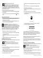 4
4
-
 5
5
-
 6
6
-
 7
7
-
 8
8
-
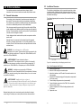 9
9
-
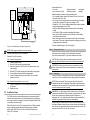 10
10
-
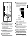 11
11
-
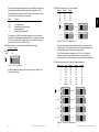 12
12
-
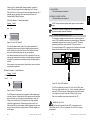 13
13
-
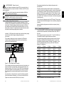 14
14
-
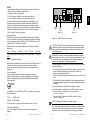 15
15
-
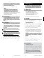 16
16
-
 17
17
-
 18
18
-
 19
19
-
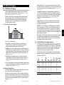 20
20
-
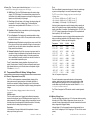 21
21
-
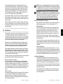 22
22
-
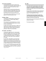 23
23
-
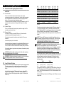 24
24
-
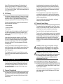 25
25
-
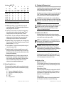 26
26
-
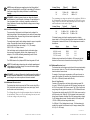 27
27
-
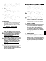 28
28
-
 29
29
-
 30
30
-
 31
31
-
 32
32
-
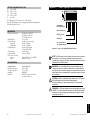 33
33
-
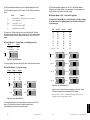 34
34
-
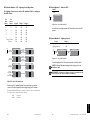 35
35
-
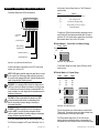 36
36
-
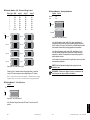 37
37
-
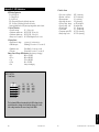 38
38
-
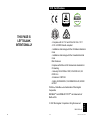 39
39


dans d''autres langues
- English: Morningstar Tristar User manual
Documents connexes
-
Morningstar EcoPulse EC-10M Manuel utilisateur
-
Morningstar Tristar MPPT Solar Charging System Controller Manuel utilisateur
-
-
-
Morningstar ProStar PS-15 Manuel utilisateur
-
Morningstar TS-MPPT 600V Manuel utilisateur
-
-
-
-
Autres documents
-
Sunforce 60032 Manuel utilisateur
-
 Go Power! Overlander Manuel utilisateur
-
Bluetti AC180 Manuel utilisateur
-
Furrion 50 Watt Rigid Solar Panel Battery Maintainer Kit Manuel utilisateur
-
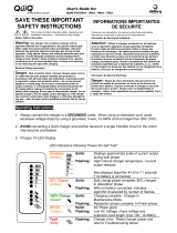 Delta-q QuiQ 912-48xx Manuel utilisateur
-
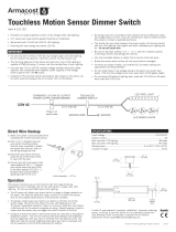 Armacost Lighting 511122 Guide d'installation
-
PowerSafe 1017 Manuel utilisateur
-
Mastervolt DC Master 24/24-7 (Isolated) Manuel utilisateur
-
Panasonic SEC-HR3U8BPN Fiche technique


