
SAVE THESE IMPORTANT
SAFETY INSTRUCTIONS
This manual contains important safety, operating, and
installation instructions – read before using charger.
Battery Safety Information
Warning: Use charger only on battery systems with an
algorithm selected that is appropriate to the specific battery type.
Other usage may cause personal injury and damage. Lead acid
batteries may generate explosive hydrogen gas during normal
operation. Keep sparks, flames, and smoking materials away from
batteries. Provide adequate ventilation during charging. Never
charge a frozen battery. Study all battery manufacturers’ specific
precautions such as recommended rates of charge and removing
or not removing cell caps while charging.
Electrical Safety Information
Danger: Risk of electric shock. Connect charger power cord to
an outlet that has been properly installed and grounded in
accordance with all local codes and ordinances. A grounded outlet
is required to reduce risk of electric shock – do not use ground
adapters or modify plug. Do not touch uninsulated portion of
output connector or uninsulated battery terminal. Disconnect the
AC supply before making or breaking the connections to the
battery while charging. Do not open or disassemble charger. Do not
operate charger if the AC supply cord is damaged or if the charger
has received a sharp blow, been dropped, or otherwise damaged in
any way – refer all repair work to qualified personnel. Not for use by
children.
INFORMATIONS IMPORTANTES
DE SÉCURITÉ
Conserver ces instructions. Ce manuel contient des instructions
importantes concernant la sécurité et le fonctionnement.
Information de Sécurité de la Batterie
Attention: Utiliser le chargeur seulement sur les batteries
avec un algorithme approprié au type spécifique de batterie.
D´autres types de batteries pourraient éclater et causer des
blessures ou dommages. Les batteries peuvent produire des gaz
explosives en service normal. Ne jamais fumer près de la batterie
et éviter toute étincelle ou flame nue à proximité de ces derniers.
Fournisser la bonne ventilation lors du chargement. Ne jamais
charger une batterie gelée. Prendre connaissance des mesures de
précaution spécifiées par le fabricant de la batterie, p. ex., vérifier
s´il faut enlever les bouchons des cellules lors du chargement de la
batterie, et les taux de chargement recommandés.
Information de Sécurité Électrique
Danger: Risque de chocs électriques. Ne pas toucher les
parties non isolées du connecteur de sortie ou les bornes non
isolées de la batterie. Toujours connecter le chargeur à une prise
de courant mise à la terre. Ne pas ouvrir ni desassembler le
chargeur – referer toute reparations aux personnes qualifiés. Pas à
l´usage des enfants.
Operating Instructions
1. Always connect the charger to a GROUNDED outlet. When using an extension cord, avoid
excessive voltage drops by using a grounded, 3-wire, 12-AWG cord no longer than 30m (100’).
2. AVOID connecting a QuiQ charger and another device to a single 15A/20A circuit or the circuit
may become overloaded.
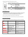
3. Charger 10-LED Display
LED indications following “Power-On Self Test”:
Ammeter
(Amber)
Solid: Displays approximate scale of current output
during bulk phase.
Flashing: High internal charger temperature. Current
output reduced.
Also displays algorithm #1-6 for 11 seconds
if no battery is connected.
80% Charge
(Amber)
Solid: Bulk charge phase complete, 80% charged.
In Absorption phase.
Flashing: With no battery connected, indicates
algorithm # selected by number of flashes.
100% Charge
(Green)
Solid: Charging complete. Charger in
Maintenance Mode.
Flashing: Absorption phase complete. In Finish phase
AC On
(Amber)
Solid: AC Power good
Flashing: Low AC Voltage, check voltage and
extension cord length (max 100’, 12-AWG).
Fault
(Red)
Flashing: Charger error. Reset charger power and
refer to Troubleshooting below.
User’s Guide for:
QuiQ 912
-
24xx / 36xx / 48xx / 72xx

4. Optional Charger Single-LED Display (internal or external)
LED indications following “Power-On Self Test”:
Green Solid: Charging complete. Charger in
Maintenance Mode.
Flashing: Short: <80% Charge.
Long: >80% Charge.
When battery is not connected: Algorithm
Number display.
Amber Flashing: Reduced Power Mode: Low AC Voltage or
High internal charger temperature.
Red Flashing: Charger error. Reset charger power and
refer to Troubleshooting below.
Maintenance Instructions
1. For flooded lead-acid batteries, regularly check water levels of each battery cell after charging
and add distilled water as required to level specified by battery manufacturer. Follow the
maintenance and safety instructions recommended by the battery manufacturer.
2. Make sure charger connections to battery terminals are tight and clean.
3. Do not expose charger to oil, dirt, mud or direct heavy water spray when cleaning vehicle.
Troubleshooting Instructions
If a fault occurs, count the number of red flashes between pauses and refer to the table below:
Red Flashes Cause Solution
Battery High Voltage Check battery size and condition and
reset charger (interrupt AC power for
15 seconds).
Battery Low Voltage Check battery size and condition and
reset charger (interrupt AC power for
15 seconds).
Charge Timeout caused by
battery pack not reaching
required voltage. Charger
output was reduced due to
high temperatures
Check connections.
Operate charger at a lower ambient
temperature.
Check Battery: battery could
not be trickle charged up to
minimum voltage
Check for shorted or damaged cells.
Over-Temperature: Charger
shut down due to high internal
temperature.
Ensure sufficient cooling air flow and
reset charger (interrupt AC power for
15 seconds).
Charger Internal Fault Reset charger (interrupt AC power
for 15 seconds). Return to qualified
service depot if fault persists.

Remote LED
(Optional)
Installation Instructions
WARNING: The output of chargers with greater than 48V may
pose an energy and/or shock hazard under normal use. These
units must be installed in the host equipment in such a manner
that the output cable and battery connections are only
accessible with the use of a tool by qualified personnel.
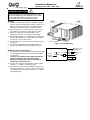
Mounting:
1) Mount the charger with adequate ventilation. Ideally it
will be mounted horizontally with airflow from below. If it
will be mounted vertically, it is recommended that the
DC-output cord be at the higher end of the charger.
2) Keep the charger free of oil, dirt, mud, or dust to keep
the cooling fins operating as efficiently as possible.
3) Mount the charger by the mounting plate using
appropriate fasteners. (ie. locking ¼” or M6 bolts)
4) For UL2202 compliance, a 12AWG green bonding wire
must be attached from the stud located on the charger
(see Figure 1) to the vehicle frame.
5) Install such that risk of human contact with hot surfaces
is reduced.
6) The charger’s AC plug must be located at least 18”
above the ground and the display visible to the user.
DC Battery Connection Procedure:
1) The green wire outputs battery voltage when the charger
is not plugged into AC to provide an interlock function
(see Figure 2).
If used, a user-supplied 1A fast-blow external fuse
must be installed in-line to prevent damage.
Shorting or drawing more than 1A may damage
charger and void the warranty.
2) Securely fasten the black ring terminal to the negative
terminal ("-", or “NEG”) of the battery pack.
3) Check that the correct charge algorithm is being used
and change algorithm if necessary. Securely fasten the
red ring terminal to the positive terminal ("+", or "POS")
of the battery pack.
Installation Manual for:
QuiQ 912
-
24xx / 36xx / 48xx / 72xx
Ground Stud
Figure 1: Charger Mounting
Figure 2:
Charger
Connections
GRN
B+
Interlock
Charger
Internal
Output
F1
NC
NO
F2
B-
BLK
RED
1A
WHT

Specifications
DC Output – see Operating Instructions
QuiQ Model: 912- 24xx 36xx 48xx 72xx
Voltage-nom (V) 24 36 48 72
Voltage-max (V) 33.6 50.4 67.2 100
Current-max (A) 25 21 18 12
Battery Type Specific to selected algorithm
Reverse Polarity Electronic protection – auto-reset
Short Circuit Electronic current limit
AC Input
All models
Voltage-max (Vrms) 85 – 265
Frequency (Hz) 45 - 65
Current - max (Arms) 12A @ 104VAC
(reduced by 20%<104V)
Current – nom (Arms) 10A @ 120VAC / 5A @ 230VAC
AC Power Factor >0.98 at nominal input current
Mechanical
All models
Dimensions 28.0 x 24.5 x 11.0 cm (11 x 9.7 x
4.3”)
Weight <5 kg (11 lbs) w/ standard cord
Environmental Enclosure: IP46
Operating
Temperature
-30°C to +50°C (-22°F to 122°F),
derated above 30°C, below 0°C
Storage Temperature -40°C to +70°C (-40°F to 158°F)
AC input connector IEC320/C14
(require ≥1.8m localized cord)
DC output connector OEM specific w/ 12AWG wire
Operation
All models
Battery Temperature
Compensation
Automatic
Maintenance Mode Auto-restart if V<2.1Vpc
or 30 days elapse
Regulatory
Safety
EN 60335-1/2-29 Safety of Appliances/ Battery Chargers
UL2202 EV Charging System Equipment
UL1564 2nd Ed. Industrial Battery Charger
CSA-C22.2 No.
107.2
Battery Chargers- Industrial
Emissions
FCC Part 15/ICES
003
Unintentional Radiators Class A
EN 55011 Radio disturbance characteristics
(Class A)
EN 61000-3-2 Limits for harmonic current emissions
EN 61000-3-3 Limits of voltage fluctuations and
flicker
Immunity
EN 61000-4-2 Electrostatic discharge immunity
EN 61000-4-3 Radiated, radio-frequency,
EMF immunity
EN 61000-4-4 Electrical fast transient/burst immunity
EN 61000-4-5 Surge immunity
EN 61000-4-6 Conducted Immunity
EN 61000-4-11 Voltage variations immunity
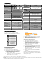
Programming Instructions
The QuiQ charger is pre-loaded with charge
algorithms for up to 10 battery types (see Table 1).
Check Default Charge Algorithm
Enter Algorithm Display Mode:
1) Disconnect AC Power.
2) Remove positive lead from battery pack.
3) Apply AC power and the charger will display the
algorithm number after the Power On Self Test:
a. All algorithms will display as a series of
flashes of the ‘80%’ LED.
b. Algorithms #1 - 6 will also be indicated by the
Ammeter LEDs (see User’s Guide).
Examples:
= Algorithm # 7
<Short Pause> =
Algorithm #43
4) Algorithm number display repeats for 11 seconds,
then Algorithm Display Mode ends.
5) Remove AC Power and reconnect positive lead.
Change Default Charge Algorithm
1) Enter Algorithm Display Mode (as above).
2) While Algorithm Number is displayed (for 11
seconds), touch positive lead to the battery pack
positive terminal for 3.0 seconds (+/- 0.5s).
3) Remove lead from battery pack. Algorithm
Number will increment.
4) To increment the Algorithm Number again, repeat
Steps 2 and 3 within 30 seconds.
5) Touch positive lead to positive terminal and hold
until relay clicks (>10 seconds). The new default
algorithm is now stored.
6) Remove AC Power and check default algorithm
(as above)
Contact your original equipment manufacturer if your
battery pack is not supported by the charge algorithms
loaded in your charger.
Alg
#
Battery Type
43
Discover AGM
37
Trojan T105 DV/DT CP -
42V pack w/ 48V charger
27
Crown CR-325
8 Concorde 10xAh AGM
7 J305 DV/DT CP
6 DEKA 8G31 Gel
5 Trojan 30/31XHS
4 US Battery USB2200
3 T105 DV/DT CP
1 Trojan T105
Table 1
Product warranty is two years
-
please contact dealer of original equipment for warranty service.
Note: This is a Class A product. In a domestic environment this product may cause radio interference, in which case the user may
be required to take adequate
measures.
Sept
ember
2008
© Delta
-
Q Technologies Corp. All rights reserved. PN:
710
-
00
23
Rev
4
-
 1
1
-
 2
2
-
 3
3
-
 4
4


Delta-q QuiQ 912-48xx Manuel utilisateur
- Taper
- Manuel utilisateur
- Ce manuel convient également à
dans d''autres langues
- English: Delta-q QuiQ 912-48xx User manual
Autres documents
-
Morningstar Tristar Manuel utilisateur
-
Victron energy Blue Smart IP67 Charger 120V Le manuel du propriétaire
-
-
-
Victron Energie Phoenix Smart 24/25 (3) Le manuel du propriétaire
-
Windsor Chariot 2 iGloss 20 Le manuel du propriétaire
-
-
-
-