Morningstar TS-MPPT 600V Manuel utilisateur
- Catégorie
- Chargeurs de batterie
- Taper
- Manuel utilisateur
Ce manuel convient également à

Installation, Operation and Maintenance Manual
Solar Charging System Controller
www.morningstarcorp.com
Solar Battery Charger with
TrakStar
TM
Maximum Power Point Tracking Technology
MODELS
TS-MPPT-60-600V-48
TS-MPPT-60-600V-48-DB
MAXIMUM POWER POINT TRACKING
T
RI
S
TAR MPPT 600V
TM
For the most recent manual revision, see the version at:
www.morningstarcorp.com

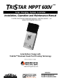
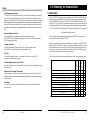
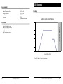
Dimensions in Inches [Millimeters] Table of Contents
1.0 Important Safety Instructions 5
2.0 Getting Started 11
2.1 Overview 11
2.2 Regulatory Information 11
2.3 Versions and Ratings 12
2.4 Features 13
2.5 Optional Accessories 17
3.0 Installation 18
3.1 General Information 18
3.2 Wiring Zones 19
3.3 Conduit Knock-outs and Wiring Routing 21
3.4 Controller Preparation 23
3.5 Mounting 26
3.6 Network Connections 28
3.7 Wiring Connections 30
3.8 Conguration 37
3.9 Power-Up & Commissioning 41
4.0 Operation 42
4.1 TrakStar
TM
MPPT Technology 42
4.2 Battery Charging Information 43
4.3 Push-button 51
4.4 LED Indications 52
4.5 Protections, Faults & Alarms 54
5.0 Networking and Communications 57
5.1 Introduction 57
5.2 Morningstar MeterBus
TM
58
5.3 Serial RS-232 59
5.4 EIA-485 (formerly RS-485) 61
5.5 Ethernet 62

5TriStar MPPT 600V Operator’s Manual
4
Table of Contents (Cont.)
6.0 Troubleshooting 66
6.1 Battery Charging and Performance Issues 66
6.2 Network and Communications Issues 67
7.0 Maintenance and Service 69
7.1 Important Safety Instructions 69
7.2 Maintenance Schedule 74
8.0 Warranty and Claim Procedure 76
9.0 Technical Specications 78
10.0 Appendix 81
11.0 Certications 89
SAVE THESE INSTRUCTIONS.
This manual contains important safety, installation and operating instructions for the
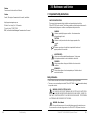
TriStar MPPT 600V solar controller. The following symbols are used throughout this manual to
indicate potentially dangerous conditions or mark important safety instructions:
WARNING:
Indicates a potentially dangerous condition. Use extreme caution
when performing this task.
!
CAUTION:
Indicates a critical procedure for safe and proper operation of the
controller.
NOTE:
Indicates a procedure or function that is important for the safe and
proper operation of the controller.
AVERTISSEMENT :
Indique une condition potentiellement dangereuse. Faites preuve
d’une prudence extrême lors de la réalisation de cette tâche.
!
PRUDENCE :
Indique une procédure critique pour l’utilisation sûre et correcte du
contrôleur.
REMARQUE :
Indique une procédure ou fonction importante pour l’utilisation sûre et
correcte du contrôleur.
Safety Information
• Read all of the instructions and cautions in the manual before beginning installation.
• There are no user serviceable parts inside the TriStar MPPT 600V. Do not disassemble
or attempt to repair the controller.
WARNING: RISK OF ELECTRICAL SHOCK.
NO POWER OR ACCESSORY TERMINALS ARE ELECTRICALLY ISOLATED FROM
DC INPUT, AND MAY BE ENERGIZED WITH HAZARDOUS SOLAR VOLTAGE. UNDER CER-
TAIN FAULT CONDITIONS, BATTERY COULD BECOME OVER-CHARGED. TEST BETWEEN
ALL TERMINALS AND GROUND BEFORE TOUCHING.
• External solar and battery disconnects are required.
• Disconnect all sources of power to the controller before installing or adjusting the
TriStar MPPT 600V.
• There are no fuses or disconnects inside the TriStar MPPT 600V Do not attempt to repair.
1.0 Important Safety Instructions

7TriStar MPPT 600V Operator’s Manual
6
Important Safety Instructions
• This charge controller is to be connected to DC circuits only. These DC connections are identied
by the symbol below:
Direct Current Symbol
The TriStar MPPT 600V controller must be installed by a qualified technician in accordance with the
electrical regulations of the country where the product is installed. A means of disconnecting all
power supply poles must be provided. These disconnects must be incorporated in the fixed wiring.
A permanent, reliable earth ground must be established with connection to the wiring compartment
ground terminal.
The grounding conductor must be secured against any accidental detachment. The knock-outs in
the wiring compartment must protect wires with conduit or rubber rings.
Précautions de Sécurité D’installation
AVERTISSEMENT: L’appareil n’est pas fourni avec un dispositif GFDI. Ce
contrôleur de charge doit être utilisé avec un dispositif GFDI externe tel que requis
par l’Article 690 du Code électrique national de l’emplacement de l’installation.
• Montez le TriStar MPPT 600V à l’intérieur. Empêchez l’exposition aux éléments et la pénétration
d’eau dans le contrôleur.
• Installez le TriStar MPPT 600V dans un endroit qui empêche le contact occasionnel. Le dissipateur
de chaleur peut devenir très chaud pendant le fonctionnement.
• Utilisez des outils isolés pour travailler avec les batteries.
• Évitez le port de bijoux pendant l’installation.
• Le groupe de batteries doit être constitué de batteries du même type, fabricant et âge.
• Ne fumez pas à proximité du groupe de batteries.
• Les connexions d’alimentation doivent rester serrées pour éviter une surchaue excessive d’une
connexion desserrée.
• Utilisez des conducteurs et des coupe-circuits de dimensions adaptées.
• La borne de mise à la terre se trouve dans le compartiment de câblage et est identiée par le
symbole ci-dessous estampillé dans le boit:
Informations de Sécurité
• Lisez toutes les instructions et les avertissements gurant dans le manuel avant de com-
mencer l’installation.
• Le TriStar MPPT 600V ne contient aucune pièce réparable par l’utilisateur. Ne démontez
pas ni ne tentez de réparer le contrôleur.
AVERTISSEMENT: RISQUE DE CHOC ÉLETRIQUE.
NON ALIMENTATION OU AUX BORNES D’ACCESSOIRES SONT ISOLÉS ÉLEC-
TRIQUEMENT DE L’ENTRÉE DE C.C ET DOIT ÊTRE ALIMENTÉS À UNE TENSION DAN-
GEREUSE SOLAIRE. SOUS CERTAINES CONDITIONS DE DÉFAILLANCE, LA BATTERIE
POURRAIT DEVENIR TROP CHARGÉE. TEST ENTRE TOUTES LES BORNES ET LA MASSE
AVANT DE TOUCHER.
External solaire et la batterie se déconnecte sont nécessaires.
• Déconnectez toutes les sources d’alimentation du contrôleur avant d’installer ou de régler
le TriStar MPPT 600V.
• Le TriStar MPPT 600V 600Vne contient aucun fusible ou interrupteur. Ne tentez pas de
réparer.
• Installez des fusibles/coupe-circuits externes selon le besoin.
Installation Safety Precautions
WARNING:
This unit is not provided with a GFDI device. This charge controller must be
used with an external GFDI device as required by the Article 690 of the National
Electrical Code for the installation location.
• Mount the TriStar MPPT 600V indoors. Prevent exposure to the elements and do not allow
water to enter the controller.
• Install the TriStar MPPT 600V in a location that prevents casual contact. The
TriStar MPPT 600V heatsink can become very hot during operation.
• Use insulated tools when working with batteries.
• Avoid wearing jewelry during installation.
• The battery bank must be comprised of batteries of same type, make, and age.
• Do not smoke near the battery bank.
• Power connections must remain tight to avoid excessive heating from a loose connection.
• Use properly sized conductors and circuit interrupters.
• The grounding terminal is located in the wiring compartment and is identied by the
symbol below.
Ground Symbol

9TriStar MPPT 600V Operator’s Manual
8
Important Safety Instructions
• Servicing of batteries should be performed, or supervised, by personnel knowledgeable about
batteries, and the proper safety precautions.
• Be very careful when working with large lead-acid batteries. Wear eye protection and have fresh
water available in case there is contact with the battery acid.
• Remove watches, rings, jewelry and other metal objects before working with batteries.
• Wear rubber gloves and boots
• Use tools with insulated handles and avoid placing tools or metal objects on top of batteries.
• Disconnect charging source prior to connecting or dis-connecting battery terminals.
• Determine if battery is inadvertently grounded. If so, remove the source of contact with ground.
Contact with any part of a grounded battery can result in electrical shock. The likelihood of such
a shock can be reduced if battery grounds are removed during installation and maint enance
(applicable to equipment and remote battery supplies not having a grounded supply circuit).
• Carefully read the battery manufacturer’s instructions before installing / connecting to, or removing
batteries from, the TriStar MPPT 600V.
• Be very careful not to short circuit the cables connected to the battery.
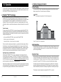
• Have someone nearby to assist in case of an accident.
• Explosive battery gases can be present during charging. Be
certain there is enough ventilation to
release the gases.
• Never smoke in the battery area.
• If battery acid comes into contact with the skin, wash with
soap and water. If the acid contacts the
eye, ood with fresh water and get medical attention.
• Be sure the battery electrolyte level is correct before starting charging. Do not attempt to charge a frozen
battery.
• Recycle the battery when it is replaced.
• Entretien des batteries devrait être eectué ou supervisé, par un personnel bien informé sur les
piles et les précautions de sécurité appropriées.
• Soyez très prudent quand vous travaillez avec des grandes batteries au plomb. Portez des lunettes
de protection et ayez de l’eau fraîche à disposition en cas de contact avec l’électrolyte.
• Enlevez les montres, bagues, bijoux et autres objets mé talliques avant de travailler avec des piles.
• Porter des bottes et des gants de caoutchouc
• Utiliser des outils avec poignées isolantes et évitez de placer des outils ou des objets métalliques
sur le dessus de batteries.
• Débrancher la source de charge avant de brancher ou dis-reliant les bornes de la batterie.
• Utilisez des outils isolés et évitez de placer des objets métalliques dans la zone de travail.
• Déterminer si batterie repose par inadvertance. Dans l’armative, supprimer la source du contact
avec le sol. Contact avec n’importe quelle partie d’une batterie mise à la terre peut entraîner un
choc électrique. La probabilité d’un tel choc peut être réduite si des motifs de batterie sont suppri-
més pendant l’installation et maintentretien (applicable à l’équipement et les fournitures de pile de
la télécommande n’ayant ne pas un circuit d’alimentation mise à la terre *).
• Lisez attentivement les instructions du fabricant de la batterie avant d’installer / connexion à ou
retrait des batteries du TriStar MPPT 600V.
• Veillez à ne pas court-circuiter les câbles connectés à la batterie.
• Ayez une personne à proximité qui puisse aider en cas d’accident.
• Ce contrôleur de charge ne doit être connecté qu’à des circuits en courant continu. Ces connex-
ions CC sont identiées par le symbole ci-dessous:
Le contrôleur TriStar MPPT 600V 600V600V doit être installé par un technicien qualié conformé-
ment aux règlementations électriques du pays où est installé le produit.
Un moyen d’assurer la déconnexion de tous les pôles de l’alimentation doit être fourni. Cette décon-
nexion doit être incorporée dans le câblage xe.
À l’aide de la borne de mise à la masse du TriStar MPPT 600V 600V600V (dans le compartiment de
câblage), un moyen permanent et able de mise à la terre doit être fourni. La xation de la mise à la
terre doit être xée contre tout desserrage accidentel.
Les ouvertures d’entrée au compartiment de câblage du TriStar MPPT 600V 600V600V doivent être
protégées avec un conduit ou une bague.
Battery Safety
WARNING: A battery can present a risk of electrical shock or burn from large amounts
of short-circuit current, re, or explosion from vented gases. Observe proper precautions.
AVERTISSEMENT: Une batterie peut présenter a ris que de choc électrique ou de brûlure
de grandes quantités de court-circuit curlouer, incendie ou explosion de ventilé gaz.
Observer précautions appropriées.
WARNING: Risk of Explosion.
Proper disposal of batteries is required. Do not dispose of batteries in re. Refer to
local regulations or codes for requirements.
AVERTISSEMENT: Risque d’Explosion.
Au rebut des piles est nécessaire. Ne pas jeter les piles dans le feu. Se référer aux régle
mentations locales ou des codes pour les exigences.
CAUTION:
When replacing batteries, proper specied number, sizes types and ratings
based on application and system design
PRUDENCE: Lorsque le remplacement des piles, utilisez correctement nombre spécifié,
tailles, types et les évaluations basées sur conception de système et d’application.
CAUTION: Do not open or mutilate batteries. Released electrolyte is harmful to skin,
and may be toxic.
PRUDENCE: Ne pas ouvrir ou mutiler les piles. L’électrolyte est nocif pour la peau et
peut être toxique.

11TriStar MPPT 600V Operator’s Manual
10
Important Safety Instructions
Getting Started2.0
2.1 Overview
Thank you for selecting the TriStar MPPT 600V charge controller with TrakStar
TM
MPPT
Technology. The TriStar MPPT 600V (TS-MPPT-60-600V) is an advanced maximum power point
tracking solar battery charger. The controller features a smart tracking algorithm that nds and
maintains operation at the power source's peak power point, maximizing energy harvest.
The TriStar MPPT 600V battery charging process has been optimized for long battery life and
improved system performance. Self-diagnostics and electronic error protections prevent damage
when installation mistakes or system faults occur. The controller also features eight (8) adjustable
settings switches, several communication ports, and terminals for remote battery temperature
and voltage measurement.
Please take the time to read this operator’s manual and become familiar with the controller. This
will help you make full use of the many advantages the TriStar MPPT 600V can provide for your
PV system.
2.2 Regulatory Information
NOTE: This section contains important information for safety
and regulatory requirements.
The TriStar MPPT 600V controller should be installed by a qualied technician according to the
electrical rules of the country in which the product will be installed.
TriStar MPPT 600V controllers comply with the following EMC standards:
• Immunity: EN61000-6-2: 2005
• Emissions: EN55022:2 2007 with A1 and A3 Class B1
• Safety: EN60335-1 and EN60335-2-29 (battery chargers)
A means shall be provided to ensure all pole disconnection from the power supply. This
disconnection shall be incorporated in the xed wiring.
Using the TriStar MPPT 600V grounding terminal (in the wiring compartment), a permanent and
reliable means for grounding shall be provided. The clamping of the earthing shall be secured
against accidental loosening.
The entry openings to the TriStar MPPT 600V wiring compartment shall be protected with conduit
or with a bushing.
FCC requirements:
This device complies with Part 15 of the FCC rules. Operation is subject to the following two
conditions: (1) This device may not cause harmful interference, and (2) this device must accept
any interference received, including interference that may cause undesired operation. Changes
or modications not expressly approved by Morningstar for compliance could void the user’s
authority to operate the equipment.
• Des gaz explosifs de batterie peuvent être présents pendant la charge. Assurez-vous qu’une venti-
lation susante évacue les gaz.
• Ne fumez jamais dans la zone des batteries
• En cas de contact de l’électrolyte avec la peau, lavez avec du savon et de l’eau. En cas de contact
de l’électrolyte avec les yeux, rincez abondamment avec de l’eau fraîche et consultez un médecin.
• Assurez-vous que le niveau d’électrolyte de la batterie est correct avant de commencer la charge.
Ne tentez pas de charger une batterie gelée.
• Recyclez la batterie quand elle est remplacée.
About this Manual
This manual provides detailed installation and usage instructions for the TriStar MPPT 600V
controller. Only qualied electricians and technicians who are familiar with solar system design
and wiring practices should install the TriStar MPPT 600V. The usage information in this manual
is intended for the system owner/operator.

13TriStar MPPT 600V Operator’s Manual
12
Getting Started
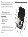
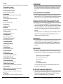
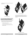
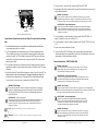
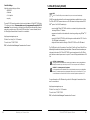
2.4 Features
The features of the TS-MPPT-60-600V-48 model are shown in Figure 2-1 below. An explanation
of each feature is provided.
1
15
14
13
3
4
5
6
7
2
17
16
8
12
11
9
10
Figure 2-1. TriStar MPPT 600V Features
NOTE:
This equipment has been tested and found to comply with the limits for a Class B digital device,
pursuant to Part 15 of the FCC rules. These limits are designed to provide reasonable protec-
tion against harmful interference in a residential installation. This equipment generates, uses,
and can radiate radio frequency energy and, if not installed and used in accordance with the
instruction manual, may cause harmful interference to radio communication. However, there is
no guarantee that interference will not occur in a particular installation. If this equipment does
cause harmful interference to radio or television reception, which can be determined by turning
the equipment on and o, the user is encouraged to try to correct the interference by one or more
of the following measures:
• Re-orient or re-locate the receiving antenna.
• Increase the separation between the equipment and receiver.
• Connect the equipment into an outlet on a circuit dierent from that to which the receiver is
connected.
• Consult the dealer or an experienced radio/TV technician for help.
This Class B digital apparatus complies with Canadian ICES-003.
Cet appareil numerique de la classe B est conforme a la norme NMB-003 du Canada.
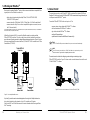
2.3 Versions and Ratings
There are two versions of TriStar MPPT 600V controller:
TS-MPPT-60-600V-48
• Maximum 60 amps continuous battery current
• 48 volt DC systems
• Maximum 600 volt DC solar input voltage
• RS-232, EIA-485, MeterBus
TM
, and Ethernet communication ports
TS-MPPT-60-600V-48-DB
• Maximum 60 amps continuous battery current
• 48 volt DC systems
• Maximum 600 volt DC solar input voltage
• RS-232, EIA-485, MeterBus
TM
, and Ethernet communication ports
• Includes enhanced wiring Disconnect Box (DB) with PV and battery disconnect switches
To comply with the National Electric Code (NEC), the current rating of the controller must be
equal to or greater than 125% of the power source’s short circuit current output (Isc). Therefore,
the maximum allowable power source input to the TriStar MPPT 600V controller for compliance
with the NEC is 48 amps Isc*
*Power source Isc @ STC

15TriStar MPPT 600V Operator’s Manual
14
Getting Started
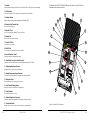
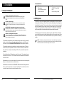
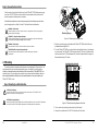
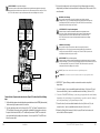
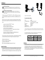
The features of the TS-MPPT-60-600V-48-DB model are shown in Figure 2-2 below. An
explanation of each feature is provided.
1
2
4
3
5
6
7
8
9
10
15
12
16
17
11
18
20
13
14
21
22
19
Figure 2-2 TriStar MPPT 600V-DB Features
1 - Heatsink
Aluminum heatsink to dissipate controller heat (the TriStar MPPT 600V is 100% passively cooled for reliability)
2 - LED Indicators
Three state of charge (SOC) LED indicators show charging status and controller faults
3 - Settings Switches
Eight (8) settings switches to congure operation of the TriStar MPPT 600V
4 - Battery Positive Terminal (red)
Power connection for Battery (+)
5 - MeterBus
TM
Port
RJ-11 socket for Morningstar MeterBus
TM
network connections
6 - Ethernet Port
RJ-45 socket for LAN/internet connections
7 - Serial RS-232 Port
9-pin serial connector (female)
8 - EIA-485 Port
Four (4) position screw terminal for EIA-485 bus connections
9 - Ground Terminals (2 total)
A chassis ground terminal for equipment grounding
10 - Blank Meter Cover (secured with 4 screws)
A plate that covers the mounting location for the optional digital meter (Model: TS-M-2-600V)
11 - Battery Negative Power Terminal
Negative terminal for negative battery cable termination
12 - Remote Temperature Sensor Terminals
Connection point for a Morningstar RTS to remotely monitor battery temperature
13 - Wiring Box Cover
Sheet metal wiring box cover protects power connections
14 - Solar Terminal Bridge (yellow)
Isolates high voltage PV wiring from low voltage wiring area
15 - Solar Terminals
Power connections for Solar (+) and (-)
16 - Battery Voltage Sense Terminals
Terminals for battery voltage input provide accurate battery voltage measurement
17 - Push-button Switch
Manually reset from an error or fault, also used to start/stop a manual equalization.

17TriStar MPPT 600V Operator’s Manual
16
Getting Started
2.5 Accessories
The accessories described below are available for purchase separately from your authorized
Morningstar dealer. Please see the individual product manuals for installation and operation
details.
Ground Fault Protection Device (GFPD-600V)
The GFPD detects power source ground faults and disconnects the as required by the U.S.
National Electrical Code. The GFPD unit is mounted in a wiring box and includes wiring hardware
needed to connect the unit to a TriStar MPPT 600V or TriStar MPPT 600V 600V600V-DB.
TriStar Meter 2-600V (TS-M-2-600V); TriStar Remote Meter 2 (TS-RM-2)
The TS-M-2-600V mounts directly on the TriStar MPPT 600V controller, replacing the blank
meter cover on the wiring box lid. The TS-RM-2 can be ush mounted in a wall or into a standard
duplex (2-gang) electrical box. A 2 x 16 character display shows system operating information,
error indications, and self-diagnostic information. Four (4) buttons make navigating the meter
menus easy.
TriStar meters connect to the RJ- 11 MeterBus
TM
port on the TriStar MPPT 600V. One meter can
display select full system information when multiple TriStar MPPT 600V or other TriStar
controllers are connected via a MeterBus
TM
network.
Meter Hub (HUB-1)
A Morningstar MeterBus
TM
network with multiple controllers requires a Meter Hub for electri-
cal isolation. The HUB-1 allows communication between MeterBus
TM
compatible Morningstar
products, including the TriStar MPPT 600V controller. DIN rail compatible. See section 5.2 for
more details.
Relay Driver (RD-1)
The Relay Driver
TM
accessory enables the TriStar MPPT 600V to control external devices. Four
(4) relay control ports can be congured (in various combinations) to perform the following tasks:
• generator control (2, 3 and 4-wire congurations)
• dry contacts for alarms and other signals
• advanced load control
• vent fan control
• DIN rail compatible or surface mount
For more information on the Relay Driver, visit our website at www.morningstarcorp.com or
inquire with your local Morningstar dealer.
EIA-485 / RS-232 Communications Adapter (RSC-1)
Connect one or more TriStar MPPT 600V controllers to a PC or to other serial devices using the
EIA-485 adapter. The adapter converts an RS-232 serial interface to EIA-485 compliant bus
signals. An LED shows network activity and errors. DIN rail compatible.
1 - Heatsink
Aluminum heatsink to dissipate controller heat (the TriStar MPPT 600V is 100% passively cooled for reliability)
2 - Battery Negative Power Terminal
Power connection for (-) battery cable termination
3 - Battery Positive Power Terminal (red)
Power connection for (+) battery cable termination
4 - Settings Switches
Eight (8) settings switches to congure operation of the TriStar MPPT 600V-DB
5 - MeterBus
TM
Port
RJ-11 socket for Morningstar MeterBus
TM
network connections
6 - Ethernet Port
RJ-45 socket for LAN/internet connections
7 - Serial RS-232 Port
9-pin serial connector (female)
8 - EIA-485 Port
Four (4) position screw terminal for EIA-485 bus connections
9 - Battery Terminal Blocks
Power connection points for Battery (+) and (-)
10 - Grounding Terminals
Chassis terminals for equipment grounding
11 - Solar Terminal Blocks (one shown)
Power connection points for solar (+) and (-)
12 - Auxilliary DIN Rail Mounts
13 - Battery Breaker (63A rating)
Battery (+) disconnect point
14 - Grounding Terminal
A chassis terminal for equipment grounding
15 - Solar Disconnect Switch
Solar (+) disconnect switch
16 - Solar Terminal Bridge (yellow)
Isolates high voltage PV wiring from low voltage wiring area
17 - Solar Negative Power Terminal
Pre-wired connection point for (-) solar cable termination
18 - Solar Positve Power Terminal
Pre-wired connection point for (+) solar cable termination
19 - Battery Voltage Sense Terminals
Terminals for battery voltage input provide accurate battery voltage measurement
20 - Push-button Switch
Manually reset from an error or fault, also used to start/stop a manual equalization.
21 - Remote Temperature Sensor Terminals
Connection point for a Morningstar RTS to remotely monitor battery temperature
22 - LED Indicators
Three state of charge (SOC) LED indicators show charging status and controller faults

19TriStar MPPT 600V Operator’s Manual18 Installation
3.1 General Information
WARNING: Equipment Damage or Risk of Explosion
Never install the TriStar MPPT 600V in an enclosure with vented/ooded batteries.
Battery fumes are ammable and will corrode and destroy the TriStar MPPT 600V
circuits.
!
CAUTION: Equipment Damage
When installing the TriStar MPPT 600V in an enclosure, ensure sucient ventilation.
Installation in a sealed enclosure will lead to over-heating and a decreased product
lifetime.
AVERTISSEMENT: Endommagement de l’équipement ou risque d’explosion
N’installez jamais le TriStar MPPT 600V 600Vdans une enceinte avec des batteries à
évent/à électrolyte liquide. Les vapeurs des batteries sont inammables et corroderont et
détruiront les circuits du TriStar MPPT 600V.
!
PRUDENCE: Endommagement de l’équipement
Assurez une ventilation susante en cas d’installation du TriStar MPPT 600V 600Vdans
une enceinte. L’installation dans une enceinte hermétique entraîne une surchaue et une
réduction de la durée de vie du produit.
The installation is straight-forward, but it is important each step is done correctly and safely. A
mistake can lead to dangerous voltage and current levels. Be sure to carefully follow each
instruction in this section. READ ALL INSTRUCTIONS FIRST before beginning installation.
The installation instructions are for installation of a negative grounded system. U.S National
Electrical Code (NEC) requirements are noted on occasion for convenience, however the in-
staller should have a complete understanding of NEC and UL requirements for photovoltaic
installations.
Solar and battery fuses or DC breakers are required in the system. These protection devices
are external to the TriStar MPPT 600V controller, and must be a maximum of 90 amps for the
TriStar MPPT 600V.
Maximum battery short-circuit current rating must be less than the interrupt current rating of the
battery over-current protection device referenced above.
Stranded wires to be connected to the TriStar MPPT 600V terminals should be prepared rst
with e.g. clamped copper heads, etc. to avoid the possibility of one conductor free out of the
connection screw, and possible contact with the metal enclosure.
Installation3.0
Recommended Tools:
• Wire strippers
• Wire cutters
• #2 & #0 Phillips screwdriver
• slotted screwdrivers
• Pliers
• Drill3/32” (2.5 mm) drill bit
• Level
• hack saw (cutting conduit)
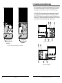
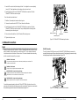
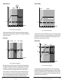
3.2 Wiring Zones
The 600V solar circuits must be separated from the low voltage battery circuits and communica-
tion wiring within the wiring box. Figure 3-1 below shows the high voltage and low voltage zones
(shaded) within the wiring box. There is overlap in the zones as pictured because the removable
wiring divider separates the high voltage solar wiring and low voltage wiring. Solar high voltage
wiring should be routed below the removable wiring divider. The yellow Solar Terminal Bridge
must be properly tted in place before making the solar power terminal connections.
The battery wiring and all communication cables must only be routed within the low voltage wir-
ing zone. After the solar wiring is installed, the wiring divider should be secured in place, and the
battery cables routed above the divider. Detailed installation steps are provided in the following
sections.
NOTE: If ALL eld wiring, including communications cable, is rated for 600V, wiring zone separation is
not required. In this case, it may be more convenient to remove the high-low voltage wiring box divider,
and terminate conduit that contains mixed voltage conductors at one point.

21TriStar MPPT 600V Operator’s Manual
20
Installation
High Voltage Wiring
Below the Removable
Wiring Divider
Figure 3-1. Low voltage and high voltage wirin
Low Voltage Wiring
Above the Removable
Wiring Divider
g zones (shaded areas)
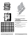
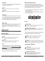
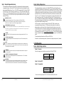
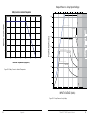
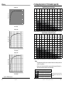
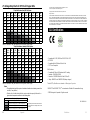
3.3 Conduit Knock-Outs and Wire Routing
Knock-outs are provided for routing cables through conduit or wire glands. Table 3-1 details the
knock-out sizes and quantity provided on the TriStar MPPT 600V wiring box. Knockout place-
ment dimensions are on the inside front cover. Figures 3-2 to 3-5 show knock-out types.
The TriStar MPPT 600V wiring box provides continuous and separate paths for high voltage
(solar) and low voltage (battery & COM) wiring routing. These allow wiring to pass between
TriStar MPPT 600V controllers that are mounted side-by-side without the need for external con-
duit tubing. Table 3-1 identies the pass-through knock-outs which may be used for this purpose.
Figure 3-6 shows the routing of the high voltage and low voltage wiring paths.
2
3
4
1
5
6
Figure 3-2. Knock-outs, left view
2
1
4
5
6
Figure 3-3. Knock-outs, right view

23TriStar MPPT 600V Operator’s Manual
22
Installation
7
8
9
10
Figure 3-4. Knock-outs, bottom view
12
11
Figure 3-5. Knock-outs, back view
Item
Quantity Trade Size Hole Dimension
Circuit(s)
Pass-Through?
1 2 (Concentric) 1” & 3/4” 1.36“ (34.5 mm) / 1.09” (27.8 mm) Solar (high voltage) YES
2 2 (Concentric) 1-1/4 “ & 1 “ 1.72” (43.7 mm) / 1.36“ (34.5 mm) Battery (low voltage) YES
3 4
Fits select MC-style
Solar connectors **
18 mm Solar (high voltage) NO
4 3 1/2” or M20 7/8” (22.2 mm) Solar (high voltage) NO
5 1 1/2” or M20 7/8” (22.2 mm) Communication YES
6 1 1.36“ (34.5 mm) Communication YES
7 2 (Concentric) 1-1/4 “ & 1 “ 1.72” (43.7 mm) / 1.36“ (34.5 mm) Battery (low voltage) NO
8 2 (Concentric) 1” & 3/4” 1.36“ (34.5 mm) / 1.09” (27.8 mm) Solar (high voltage) NO
9 4 1/2” or M20 0.88” (22.2 mm) Solar (high voltage) NO
10 4 1/2” or M20 0.88” (22.2 mm) Battery (low voltage) NO
11 2 3/4” 1.09” (27.8 mm) Solar (high voltage) NO
12 2 1” 1.36“ (34.5 mm) Battery (low voltage) NO
** Solar connector mounting hole diameters vary. Wieland Solar DC connectors recommended.
Table 3-1. Knock-out sizes
Solar Wiring
Battery Wiring
Communication
Wiring
Figure 3-6. Wiring pass-through paths between multiple controllers
3.4 Controller Preparation (TS-MPPT-60-600V-48 and
TS-MPPT-60-600V-48-DB)
Step 1 - Remove the Wiring Box Cover
CAUTION: Shock Hazard
Disconnect all power sources to the controller before removing the wiring box cover. Never
remove the cover when voltage exists on any of the TriStar MPPT 600V power connections.
PRUDENCE : Risque de décharge électrique
Déconnectez toutes les sources d’alimentation du contrôleur avant d’enlever le couvercle
du boîtier de câblage. Ne retirez jamais le couvercle en présence de tension sur une des
connexions d’alimentation du TriStar MPPT 600V 600V600V.
!
!

25TriStar MPPT 600V Operator’s Manual
24
Installation
Use a #2 Phillips screw driver to remove the four (4) screws that secure the wiring box cover as
shown in gure 3-7 below.
Figure 3-7. Remove the wiring box cover
Step 2 - Remove the Wiring Divider (TS-MPPT-60-600-V48 and TS-MPPT-60-
600V-48-DB) and Solar Terminal Bridge (TS-MPPT-60-600V-48 ONLY)
The wiring divider separates the solar high voltage wiring from the low voltage battery and
communication circuits. See Figure 3-8 . The divider is secured with only one screw.
1. Use a #2 Philips screw driver to remove the screw.
2. Lift and tilt the divider towards the bottom of the unit as shown in Figure 3-8.
3. Lift the divider out of the wiring box and set the divider and screw aside. The divider
must be replaced in a later step.
1
2
3
Figure 3-8. Remove the Wiring Divider
The Solar Terminal Bridge provides a safe path between the Solar power terminals and the
600V high voltage wiring area. The bridge is removable to allow access to the conduit knock-outs
below the bridge. To remove the bridge, gently pull the bridge straight out of the wiring box as
shown in gure 3-9.
Figure 3-9. Remove the Solar Terminal Bridge.

27TriStar MPPT 600V Operator’s Manual
26
Installation
Step 3 - Remove the Knock-Outs
Plan the routing of each cable that will connect to the TriStar MPPT 600V before removing any
knock-outs. The 1/2” (M20) knock-outs are ideal for routing network cables, which must be
placed in separate conduit from power conductors.
Use a at head screwdriver to remove the necessary knock-outs. A hammer may also be re-
quired to apply extra force. Refer to Section 3.2 for detailed knockout information.
WARNING: Shock Hazard
Always use bushings, connectors, clamp connectors, or wire glands in the knock-out openings to
protect wiring from sharp edges.
PRUDENCE : Risque de décharge électrique
Utilisez toujours des bagues, des connecteurs, des raccordements à collets ou des fouloirs dans
les ouvertures an de protéger le câblage des bords coupants.
WARNING: Shock Hazard
Never route network cables in the same conduit as the power conductors.
AVERTISSEMENT: Risque de décharge électrique
N’acheminez jamais les câbles réseau dans le même conduit que les conducteurs
d’alimentation.
3.5 Mounting
The mounting location is important to the performance and operating life of the controller. The
environment must be dry and protected from water ingress. If required, the controller may be
installed in a ventilated enclosure with sucient air ow. Never install the TriStar MPPT 600V in a
sealed enclosure. The controller may be mounted in an enclosure with sealed batteries, but never
with vented/ooded batteries. Battery fumes from vented batteries will corrode and destroy the
TriStar MPPT 600V circuits.
Step 4 - Mounting to a Vertical Surface
CAUTION: Risk of Burns
Install the TriStar MPPT 600V in a location that prevents casual contact. The TriStar MPPT 600V
heatsink can become very hot during operation.
ATTENTION : Risque de brûlures
installez le TriStar MPPT 600V 600V600V dans un endroit qui empêche le contact occasionnel. Le dissipateur
de chaleur TriStar MPPT 600V 600V600V peut devenir très chaude pendant le fonctionnement.
!
!
M6 Screw
Mounting Hanger
Figure 3-10. Attaching the mounting hanger
1. Attach the mounting hanger to the bottom of the TriStar MPPT 600V with the M6 screw
provided as shown in gure 3-10.
2. Place the TriStar MPPT 600V on a vertical surface protected from direct sun, high tempera-
tures, and water. The TriStar MPPT 600V requires at least 6” (150 mm) of clearance above
and below and at least 1” (25 mm) between the controller and adjacent walls for proper air
ow as shown in gure 3-11 below.
AT LEAST
1” (25 mm)
AT LEAST
6” (150 mm)
AT LEAST
6” (150 mm)
COOL AIR
WARM AIR
Figure 3-11. Required mounting clearance for air ow
3. Place a mark on the mounting surface at the top of the keyhole.
4. Remove the controller and drill a 3/32” (2.5 mm) hole at the drill mark.

29TriStar MPPT 600V Operator’s Manual
28
Installation
5. Insert a #10 screw (included) into the top pilot hole. Do not tighten the screw completely.
Leave a 1/4” (6 mm) gap between the mounting surface and screw head.
6. Carefully align the keyhole on the TriStar MPPT 600V with the screw head. Slide the
TriStar MPPT 600V down over the keyhole.
Check for vertical plumb with a level.
7. Mark four (4) mounting hole locations in the wiring box.
8. Remove the controller and drill 3/32” (2.5 mm) holes at the drill marks.
9. Carefully align the keyhole on the TriStar MPPT 600V with the screw head. Slide the
TriStar MPPT 600V down over the keyhole. The pre-drilled pilot holes should align with
the mounting holes in the wiring box.
10. Secure the controller with four (4), for DB model, #10 mounting screws.
11. Tighten the keyhole screw.
3.6 Network Connections
Step 5
Network connections allow the TriStar MPPT 600V to communicate with other controllers or com-
puters. A network can be as simple as one controller and one PC, or as complex as dozens of
controllers monitored via the internet. Review section 5.0 for more information about networking
and the connection(s) required for your system.
WARNING: Shock Hazard
Only route network cables in the same conduit as the photovoltaic power conductors if all
conductors are rated for 600V.
WARNING: Shock Hazard
Only use 300 volt or higher UL rated communication cable.
AVERTISSEMENT: Risque de décharge électrique
Seulement acheminez les câbles de réseau dans le même conduit que les conducteurs
d'alimentation si tous les conducteurs sont évalués à 600 V.
AVERTISSEMENT : Risque de décharge électrique
Utilisez uniquement 300 volts ou supérieur UL câble de communication.
Connect the appropriate network cables to the TriStar MPPT 600V at this time. Access to the
network ports is easier before the battery power cables are attached. The ports are located inside
the conduit wiring box on the lower circuit board as shown in gure 3-12.
EIA-485 (4 - position)
RJ-45 Ethernet
RJ-11 MeterBus
TM
RS-232 (9 - pin female)
Figure 3-12. TriStar MPPT 600V network port locations
EIA-485 Connection
The four (4) position EIA-485 connector on the TriStar MPPT 600V 600Vmust be removed to
access the terminal screws. Remove the socket connector by rmly grasping the connector body
and pulling away from the circuit board as shown in gure 3-13.
Figure 3-13. Removing the EIA-485 socket connector

31TriStar MPPT 600V Operator’s Manual
30
Installation
Minimum Wire Size (Field Wiring Connections Only)
The NEC requires that the wires carrying the system current never exceed 80% of the
conductor's current rating. Table 3.2 below provides the minimum size of copper wire for battery
output connections allowed by NEC for both TriStar MPPT 600V models when the output current
equals the full nameplate rating. Wire types rated for 75°C and 90°C are included.
* The TS-MPPT-60-600V-48-DB comes pre-wired with #6 AWG copper wire. If replacement is
required, use #6 AWG or larger wire.
** The TS-MPPT-60-600V-48-DB comes pre-wired with #6 AWG copper wire. If replacement is
required, use only copper conductors.
Wire Type 75°C Wire 90°C Wire
Copper 4 AWG (21 mm
2
) 6 AWG (13 mm
2
)
Aluminum 2 AWG (34 mm
2
) 4 AWG (21 mm
2
)
Table 3-2 Minimum Output Wire Sizes
Disconnects
WARNING: Shock Hazard
Fuses, circuit breakers, and disconnect switches should never open grounded system conductors. Only
GFDI devices are permitted to disconnect grounded conductors.
AVERTISSEMENT : Risque de décharge électrique
Les fusibles, coupe-circuits et interrupteurs ne doivent jamais ouvrir les conducteurs du système mis à la
terre. Seuls les dispositifs GFDI sont autorisés à déconnecter les conducteurs reliés mis à la terre.
Circuit breakers or fuses must be installed in both the battery and solar circuits. The protection
device ratings and installation methods must conform to NEC requirements.
WARNING: The TriStar MPPT 600V is not protected against PV short circuit faults. A breaker
or fuse, close to the controller, in the (+) PV input wire will also protect the PV wiring
against a short that may draw battery current backwards through the product.
AVERTISSEMENT : Le TS-MPPT-600V-TR n’est pas protégé contre les défauts de court-circuit de PV.
Un disjoncteur fusible, ou près du programmateur, dans le signe (+) PV d’entrée l protégera également le
câblage PV contre un court-circuit qui peut tirer une batterie courant en arrière à travers le produit.
Connect the Power Wires - TS-MPPT-60-600V-48
WARNING: Shock Hazard
The solar PV power source can produce open-circuit voltages in excess of 500 Vdc
when in sunlight. Verify that the solar input breaker or disconnect has been opened
(disconnected) before installing the system wires.
AVERTISSEMENT : Risque de décharge électrique
Le réseau PV solaire peut produire des tensions de circuit ouvert supérieures à 500 V cc
à la lumière du soleil. Vériez que le coupe-circuit ou l’interrupteur d’entrée solaire a été
ouvert (déconnexion) avant d’installer les câbles du système.
RS-232 Connection
The serial RS-232 port is a standard 9-pin (DB9) female connector. A low-prole serial connector
is recommended to save room in the wiring box.
NOTE:
The RS-232 and EIA-485 ports share hardware. Both ports cannot be used simultaneously.
REMARQUE :
Les ports RS-232 et EIA-485 partagent le matériel. Ils ne peuvent pas être utilisés simultanément.
Ethernet Connection
The RJ-45 Ethernet jack features two (2) indicator LEDs for connection status and network traf-
c. Use CAT-5 or CAT-5e twisted pair cable and RJ-45 plugs. If possible, pull the network cable
through conduit before crimping on the RJ-45 connectors. If using pre-assembled cables, take
care not to damage the plugs when the cables are pulled through conduit.
MeterBus
TM
Connection
MeterBus
TM
networks use standard 4-wire or 6-wire RJ-11 telephone cables. If possible, pull the
telephone cable through conduit before crimping on the RJ-11 connectors. If using
pre-assembled cables, take care not to damage the plugs when the cables are pulled through
conduit.
3.7 Wiring Connections
Step 6 - Power Connections
NOTE:
To comply with the NEC, the TriStar MPPT 600V must be installed using wiring methods in
accordance with the latest edition of the National Electric Code, NFPA 70.
REMARQUE :
Pour la conformité CNE, le TriStar MPPT 600V 600Vdoit être installé selon des méthodes de
câblage conformes à la dernière édition du Code électrique national, NFPA 70.
Wire Size
The four large power terminals are sized for 14 - 2 AWG (2.5 - 34 mm
2
) wire.* The terminals are
rated for copper and aluminum conductors.** Use only UL-listed Class B 300 Volt stranded wire
for battery connections. Good system design generally requires large conductor wires for the
solar and battery connections that limit voltage drop losses to 2% or less. The wire tables in the
appendix on pages 77-80 provide wire sizing information for connecting the power source and
battery bank to the TriStar MPPT 600V with a maximum of 2% voltage drop.

33TriStar MPPT 600V Operator’s Manual
32
Installation
SOLAR NEG. (-)
SOLAR POS. (+)
BATTERY NEG. (-)
BATTERY POS. (+)
Figure 3-14. Power Terminal Locations
Connect the four (4) power conductors shown in Figure 3-14 as described in the following
steps:
1. Conrm that the system input and output disconnect switches are both turned o before
connecting the power wires to the controller.
2. Pull PV and battery wires into the standard wiring box. The Remote Temperature Sensor
(RTS) and Battery Sense wires can be routed inside conduit along with the battery power
conductors if required. The RTS and Battery Sense wires CANNOT be routed in the same
conduit with the high voltage solar conductors. It is easier to pull the RTS and Sense wires
before the power cables.
3. Only route high voltage solar circuit conductors in the high voltage wiring zone and low volt-
age battery and network conductors within the low voltage zone. Refer to section 3.2 for more
information.
4. Replace the yellow Solar Terminal Bridge if removed as shown in Figure 3-9 on page 25. The
bridge should t over the solar power terminals. The bridge isolates the high voltage solar
wiring from the low voltage wiring area. The bridge MUST be installed before proceeding.
Connect the solar (+) wire to the solar (+) terminal on the TriStar MPPT 600V.
WARNING: Risk of Damage
Be very certain that the solar connection is made with correct polarity. Turn on the solar
power source breaker/disconnect and measure the voltage on the open wires BEFORE
connecting to the TriStar MPPT 600V. Disconnect the solar breaker/disconnect before
wiring to the controller.
AVERTISSEMENT : Risque d’endommagement
Assurez-vous que la connexion solaire est eectuée avec la polarité correcte. Activez le coupe-
circuit/interrupteur de réseau solaire et mesure la tension sur les câbles ouverts AVANT la
connexion au TriStar MPPT 600V. Déconnectez le coupe-circuit/interrupteur solaire avant le
câblage sur le contrôleur.
NOTE:
Tighten all new screw terminal connections to specified torque values
REMARQUE :
Serrer toutes les nouvelles connexions terminal vis au couple spécifié de valeurs
5. Connect the solar (-) wire to the solar (-) terminal on the TriStar MPPT 600V.
6. Replace the Wiring Divider (removed in Step 2 on page 24) over the solar wires, and secure it
with the M4 screw provided.
WARNING: Risk of Damage
Be very certain that the battery connection is made with correct polarity. Turn on the battery
breaker/disconnect and measure the voltage on the open battery wires BEFORE connecting to
the TriStar MPPT 600V. Disconnect the battery breaker/disconnect before wiring to the controller.
AVERTISSEMENT : Risque d’endommagement
Assurez-vous que la connexion a la batterie est eectuée avec la polarité correcte. Activez le
coupe-circuit/interrupteur de la batterie et mesure la tension sur les câbles ouverts AVANT la
connexion au TriStar MPPT 600V. Déconnectez le coupe-circuit/interrupteur de la batterie avant
le câblage sur le contrôleur.
7. Connect the battery (+) wire to the battery (+) terminal on the TriStar MPPT 600V. The
battery (+) terminal has a red cover. See Figure 3-14.
8. Connect the battery (-) wire to the battery (-) terminal on the TriStar MPPT 600V. See Figure
3-14.
9. Replace cover, and secure with four (4) screws.
10. Connect the TriStar MPPT 600V battery (+) wire (using a properly sized inline external
breaker at the battery) to the system battery (+) post; then connect the battery (-) wire to the
system battery (-)
post
(system battery not shown).
Connect the Power Wires - TS-MPPT-60-600V-48-DB
WARNING: Shock Hazard
The solar PV power source can produce open-circuit voltages in excess of 500 Vdc
when in sunlight. Verify that the solar input breaker or disconnect has been opened
(disconnected) before installing the system wires.
AVERTISSEMENT : Risque de décharge électrique
Le réseau PV solaire peut produire des tensions de circuit ouvert supérieures à 500 V cc
à la lumière du soleil. Vériez que le coupe-circuit ou l’interrupteur d’entrée solaire a été
ouvert (déconnexion) avant d’installer les câbles du système.
WARNING: Risk of Damage
Be very certain that the battery connection is made with correct polarity. Turn on the battery breaker/
disconnect and measure the voltage on the open battery wires BEFORE connecting to the TriStar MPPT 600V.
Disconnect the battery breaker/disconnect before wiring to the controller.
AVERTISSEMENT : Risque d’endommagement
Assurez-vous que la connexion a la batterie est eectuée avec la polarité correcte.
Activez le coupe-circuit/interrupteur de la batterie et mesure la tension sur les câbles
ouverts AVANT la connexion au TriStar MPPT 600V. Déconnectez le coupe-circuit/
interrupteur de la batterie avant le câblage sur le contrôleur.
WARNING: Risk of Damage
Be very certain that the solar connection is made with correct polarity. Turn on the solar
power source breaker/disconnect and measure the voltage on the open wires BEFORE
connecting to the TriStar MPPT 600V. Disconnect the solar breaker/disconnect before
wiring to the controller.

35TriStar MPPT 600V Operator’s Manual
34
Installation
AVERTISSEMENT: Risque d’endommagement
Assurez-vous que la connexion solaire est eectuée avec la polarité correcte. Activez le coupe-circuit/
interrupteur de réseau solaire et mesure la tension sur les câbles ouverts AVANT la connexion au TriStar
MPPT 600V. Déconnectez le coupe-circuit/interrupteur solaire avant le câblage sur le contrôleur.
Figure 3-15. Power Terminal Locations
Connect the four (4) power conductors shown in Figure 3-15 as described in the following
steps:
1. Conrm that the system solar and battery disconnect switches are both OPEN (disconnected)
before connecting the power wires to the controller.
2. Pull solar and battery wires into the Disconnect Box (DB). The Remote Temperature Sensor
(RTS) and Battery Sense wires can be routed inside conduit with the battery power conductors,
if required. Unless rated for 600V, the RTS and Battery Sense wires CANNOT be routed in the
same conduit with the high voltage solar conductors. It is easier to pull the RTS and BVS wires
before the power cables.
3.
Only route high voltage solar circuit conductors in the high voltage wiring zone and low
voltage battery and network conductors within the low voltage zone. Refer to section 3.2 for
more information.
WARNING: Risk of Damage
Be very certain that the battery connection is made with correct polarity, otherwise,
damage will occur.. Turn on the battery breaker/disconnect and measure the voltage on the
open battery wires BEFORE connecting to the TriStar MPPT 600V. Disconnect the battery
breaker/disconnect before wiring to the controller.
AVERTISSEMENT : Risque d’endommagement
Assurez-vous que la connexion a la batterie est eectuée avec la polarité correcte.
dans le cas contraire, subira des dommages. Activez le coupe-circuit/interrupteur de la
batterie et mesure la tension sur les câbles ouverts AVANT la connexion au TriStar
MPPT 600V. Déconnectez le coupe-circuit/interrupteur de la batterie avant le câblage
sur le contrôleur.
WARNING: Risk of Damage
Be very certain that the solar connection is made with correct polarity, otherwise,
damage will occur.. Turn on the solar power source breaker/disconnect and measure the
voltage on the open wires BEFORE connecting to the TriStar MPPT 600V. Open the solar
breaker/disconnect before wiring to the controller.
AVERTISSEMENT: Risque d’endommagement
Assurez-vous que la connexion solaire est eectuée avec la polarité correcte, dans le cas contraire,
subira des dommages. . Activez le coupe-circuit/interrupteur de réseau solaire et mesure la tension sur
les câbles ouverts AVANT la connexion au TriStar MPPT 600V. Déconnectez le coupe-circuit/
interrupteur solaire avant le câblage sur le contrôleur.
NOTE:
Tighten all new screw terminal connections to specified torque values
REMARQUE : Serrer toutes les nouvelles connexions terminal vis au couple spécifié de valeurs
4.
IMPORTANT: Tighten all factory pre-wired screw terminal connections to specified
torque values.
5. Connect the battery (+) wire to an available terminal on the battery (+) block as in (B+), and
then connect the battery (-) wire to an available terminal on the battery (-) block as in (B-).
6. Connect the
TriStar MPPT 600V
battery (+) wire (using a properly sized inline external breaker,
if required by code) at the battery, to the system battery (+) post; then connect the battery (-)
wire to the system battery (-) post (system battery not shown).
7. Connect the solar (+) wire to an available terminal on the solar (+) block as in (S+), and
connect the solar (-) wire to an available terminal on the solar (-) block as in (S-).
8.
Replace the Wiring Divider (removed in Step 2 on page 24) over the solar wires, and
secure it with the M4 screw provided.
1
BATTERY
TERMINAL
LUGS
(+)
(+) Block
(+) Block
(-) Block
(-) Block
(+)
(-)
TO BATTERY
FROM
ARRAY
High-Low Voltage
Barrier Not Shown
PV
TERMINAL
LUGS
PV SWITCH
(-)
(-)
(+)
BATTERY
DISCONNECT
BREAKER
Runs Below (+)
Terminal Block
S+
B+
S -
B -

37TriStar MPPT 600V Operator’s Manual
36
Installation
Step 7 - Remote Temperature Sensor
The included Remote Temperature Sensor (RTS) is recommended for eective temperature
compensated charging. Connect the RTS to the 2-position terminal located between the push-
button and the LEDs (see gure 2-1 on p. 13). The RTS is supplied with 33 ft (10 m) of 22 AWG
(0.34 mm
2
) cable. There is no polarity, so either wire (+ or -) can be connected to either screw
terminal. The RTS cable may be pulled through conduit along with the power wires. Tighten the
connector screws to 5 in-lb (0.56 Nm) of torque. Separate installation instructions are provided
inside the RTS bag.
WARNING: Risk of Fire.
If no Remote Temperature Sensor (RTS) is connected, use the TriStar MPPT 600V
within 3m (10 ft) of the batteries. Internal Temperature Compensation will be used if
the RTS is not connected. Use of the RTS is strongly recommended.
AVERTISSEMENT
: Risque d’incendie.
Si non Capteur de température distant (RTS) est connecté, utilisez le MPPT ProStar moins de 3m (10 pi)
de les batteries. Compensation de la température interne sera utilisée si la RTS n’est pas connecté.
Utilisation de la RTS est fortement recommandé.
!
CAUTION:
The TriStar MPPT 600V will not temperature compensate charging parameters if the RTS is not
used.
!
CAUTION: Equipment Damage
Never place the temperature sensor inside a battery cell. Both the RTS and the battery will be
damaged.
NOTE:
The RTS cable may be shortened if the full length is not needed. Be sure to reinstall the ferrite
choke on the end of the RTS if a length of cable is removed. This choke ensures compliance with
electromagnetic emissions standards.
!
PRUDENCE :
Le TriStar MPPT 600V 600Vne compense pas la température des paramètres de charges si le
RTS n’est pas utilisé.
!
PRUDENCE : Endommagement de l’équipement
Ne placez jamais la sonde de température dans un élément de batterie. Le RTS et la batterie
seraient endommagés.
REMARQUE :
Le câble de RTS peut être raccourci si la totalité de la longueur n’est pas nécessaire. Assurez-
vous de réinstaller la bobine en ferrite sur l’extrémité du RTS si une longueur de câble est
enlevée. Cette bobine assure la conformité avec les normes d’émissions électromagnétiques.
Step 8 - Battery Voltage Sense
The voltage at the battery connection on the TriStar MPPT 600V may dier slightly from the
voltage directly at the battery bank terminals due to connection and cable resistance. The Battery
Voltage Sense (BVS) connection enables the TriStar MPPT 600V to measure the battery terminal
voltage precisely with small gauge wires that carry very little current, and thus have no voltage
drop. Both BVS wires are connected to the TriStar at the 2-position terminal indicated by #16 in
Figure 2-1, on p. 13. No damage will occur if the polarity is reversed, but the controller cannot
read a reversed sense voltage. Connecting the BVS wires to the RTS terminal will cause an
alarm. If a TriStar meter is installed, check the “TriStar Settings” to conrm the BVS and the RTS
(if installed) are both present and detected by the controller. MSView
TM
PC software can also be
used to conrm the BVS is working correctly.
A BVS connection is not required to operate your TriStar MPPT 600V controller, but it is
recommended for best performance. If a TriStar meter will be added to the controller, the
battery voltage sense will ensure that the voltage and diagnostic displays are very accurate.
The BVS wires should be cut to length as required to connect the battery to the voltage sense
terminal. The wire size can range from 16 to 24 AWG (1.0 to 0.25 mm
2
). A twisted pair cable is
recommended but not required. Use UL rated 300 Volt conductors. The BVS wires may be pulled
through conduit with the power conductors. Tighten the connector screws to 5 in-lb (0.56 Nm) of
torque.
The maximum length allowed for each BVS wire is 98 ft (30 m).
Be careful to connect the battery positive (+) terminal to the voltage sense positive (+) terminal.
3.8 Conguration
Step 9 - Adjust Settings Switches
Switch 1: Future Use
Select the charging source that will be connected to the TriStar MPPT 600V.
Mode Switch 1
Solar Charging OFF
Future Use ON
Switch 2: Not Used (OFF)
Switch 3: Charging Mode
Charging Mode Switch 3
Normal 48V OFF
Custom Multiplier* ON
* Allows for nominal charging voltages of 24, 36, or 60V. Battery compatibility must be veried.

39TriStar MPPT 600V Operator’s Manual
38
Installation
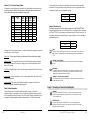
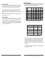
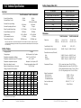
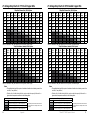
Switches 4, 5, & 6: Battery Charging Settings
It is important to select the battery type that matches the system battery to ensure proper charg-
ing and long battery life. Refer to the specications provided by the battery manufacturer and
choose a setting that best ts the recommended charging prole.
Settings
Switches
4 - 5 - 6
Battery
Type
Absorp.
Stage
(Volts)
Float
Stage
(Volts)
Equalize
Stage
(Volts)
Equalize
Interval
(Days)
off-off-off 1 - Gel 56.00 54.80
off-off-on 2 - Sealed* 56.60 54.80 57.60 28
off-on-off 3 - Sealed* 57.20 54.80 58.40 28
off-on-on 4 - AGM/Flooded 57.60 54.80 60.40 28
on-off-off 5 - Flooded 58.40 54.00 61.20 28
on-off-on 6 - Flooded 58.80 54.00 61.60 28
on-on-off 7 - L-16 61.60 53.60 64.00 14
on-on-on 8 - Custom Custom Custom Custom Custom
* “Sealed” battery type includes gel and AGM batteries
All settings are for 48 volt nominal systems. Descriptions of battery type and stages are provided
below. See section 4.2 for full details.
Battery Type - The most common battery type associated with the specied charging settings.
Absorption Stage - This stage limits input current so that the Absorption voltage is maintained.
As the battery becomes more charged, the charging current continues to taper down until the
battery is fully charged.
Float Stage - When the battery is fully charged, the charging voltage will be reduced to the Float
voltage setting.
Equalize Stage - During an equalization cycle, the charging voltage will be held constant at the
specied voltage setting.
Equalize Interval - The number of days between equalization charges when the controller is
congured for automatic equalizations (settings switch 7).
Switch 7: Battery Equalization
Choose between manual and automatic battery equalization charging. In the manual
equalization setting, an equalization will only occur when manually started with the push-button
or when requested from the equalize menu on the TriStar meter. Automatic equalization will occur
according to the battery program specied by settings switches 4, 5, & 6 in the previous step.
In both settings (auto and manual), the push-button can be used to start and stop battery
equalization. If the selected battery charging setting does not have an equalization stage, an
equalization will never occur, even if requested manually.
Equalize Switch 7
manual OFF
automatic ON
Switch 8: Ethernet Security
The Ethernet Security switch enables or disables conguration of the TriStar MPPT 600V
settings through the Ethernet connection. When switch 8 is set to disabled, write commands to
the TriStar MPPT 600V custom memory are not allowed through the Ethernet connection. This
safety feature will prevent unintended changes to custom settings, but it is not a substitute for
proper network security.
Conguration via TCP/IP Switch 8
disabled OFF
enabled ON
NOTE:
Adjustment of network settings and custom set-points is always enabled via the RS-232 and EIA-
485 connections. The Ethernet Security switch only enables/disables remote conguration via
TCP/IP.
!
CAUTION: Risk of Tampering
The Ethernet Security settings switch does not block write commands to devices bridged via
EIA-485.
REMARQUE :
Le réglage des paramètres de réseau et des points de consignes personnalisés est toujours
activé par les connexions RS-232 et EIA-485. Le contacteur de sécurité Ethernet n’active/
désactive que la conguration à distance par TCP/IP.
!
PRUDENCE : Risque de tentative d’altération
Le contacteur des paramètres de sécurité Ethernet ne bloque pas les commandes d’écriture sur
les dispositifs reliés par EIA-485.
Step 10 - Grounding and Ground-Fault Interruption
WARNING:
This unit is not provided with a GFDI device. This charge controller must be used with an
external GFDI device as required by the Article 690 of the U.S. National Electrical Code
for the installation location.
AVERTISSEMENT :
L’appareil n’est pas fourni avec un dispositif GFDI. Ce contrôleur de charge doit être
utilisé avec un dispositif GFDI externe tel que requis par l’Article 690 du Code électrique
national de la région de l’installation.
La page est en cours de chargement...
La page est en cours de chargement...
La page est en cours de chargement...
La page est en cours de chargement...
La page est en cours de chargement...
La page est en cours de chargement...
La page est en cours de chargement...
La page est en cours de chargement...
La page est en cours de chargement...
La page est en cours de chargement...
La page est en cours de chargement...
La page est en cours de chargement...
La page est en cours de chargement...
La page est en cours de chargement...
La page est en cours de chargement...
La page est en cours de chargement...
La page est en cours de chargement...
La page est en cours de chargement...
La page est en cours de chargement...
La page est en cours de chargement...
La page est en cours de chargement...
La page est en cours de chargement...
La page est en cours de chargement...
La page est en cours de chargement...
La page est en cours de chargement...
-
 1
1
-
 2
2
-
 3
3
-
 4
4
-
 5
5
-
 6
6
-
 7
7
-
 8
8
-
 9
9
-
 10
10
-
 11
11
-
 12
12
-
 13
13
-
 14
14
-
 15
15
-
 16
16
-
 17
17
-
 18
18
-
 19
19
-
 20
20
-
 21
21
-
 22
22
-
 23
23
-
 24
24
-
 25
25
-
 26
26
-
 27
27
-
 28
28
-
 29
29
-
 30
30
-
 31
31
-
 32
32
-
 33
33
-
 34
34
-
 35
35
-
 36
36
-
 37
37
-
 38
38
-
 39
39
-
 40
40
-
 41
41
-
 42
42
-
 43
43
-
 44
44
-
 45
45


Morningstar TS-MPPT 600V Manuel utilisateur
- Catégorie
- Chargeurs de batterie
- Taper
- Manuel utilisateur
- Ce manuel convient également à
dans d''autres langues
- English: Morningstar TS-MPPT 600V User manual
Documents connexes
-
Morningstar EcoPulse EC-10M Manuel utilisateur
-
-
Morningstar Tristar MPPT Solar Charging System Controller Manuel utilisateur
-
-
-
-
-
-
-
Autres documents
-
Sunforce 60032 Manuel utilisateur
-
tbs electronics OCS 100-20 Le manuel du propriétaire
-
 Alarm ADC-S40-DC Guide d'installation
-
tbs electronics OCS 150-60 Le manuel du propriétaire
-
 Allen-Bradley 1492-PDE1C142 Installation Instructions Manual
-
 Setra Systems Power Meter (Multi-Load) Mode d'emploi
-
Honeywell UL60730-1 Optimizer Advanced Controller Manuel utilisateur


