Haier AU48NFIERA Guide d'installation
- Catégorie
- Climatiseurs split-system
- Taper
- Guide d'installation
Ce manuel convient également à

No. 0150506826
Please read this manual carefully before using this air conditioner
Please keep this manual safely for future use
OUTDOOR UNIT
INSTALLATION MANUAL
EN
MANUALE DI INSTALLAZIONE
IT
MANUEL D’INSTALLATION
FR
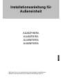
INSTALLATIONSANLEITUNG
DE
MANUAL DE INSTALACIÓN
ES
R410A MRVII-S
AU282FHERA
AU482FIERA
AU48NFIERA
AU60NFIERA


AU282FHERA AU482FIERA AU48NFIERA AU60NFIERA
CE
Tutti i prodotti sono conformi alle seguenti normative europee:
- Direttiva 73/23/EEC Basso Voltaggio
- Direttiva 2006/95/EC Basso Voltaggio
- Direttiva 89/336/EEC Compatibilità elettromagnetica
ROHS
Il prodotto è conforme alla normativa 2002/95/EEC sulla restrizione d’uso di
sostanze inquinanti negli apparecchi elettrici ed elettronici.
WEEE
Informativa al consumatore come previsto dalla normativa europea
2002/96/CE riguardante i rifiuti di apparecchiature elettriche ed elettroniche.
SPECIFICHE DI SMALTIMENTO:
Il climatizzatore è contrassegnato con questo simbolo,
ciò significa che i prodotti elettrici ed elettronici non
possono essere smaltiti insieme ai rifiuti domestici non
differenziati. Non cercare di demolire il sistema da soli:
la demolizioni dei sistemi di condizionamento, nonché il
recupero del refrigerante, dell’olio e di qualsiasi altra
parte devono essere eseguiti da un installatore qualifi-
cato in conformità alla legislazione locale e nazionale
vigente in materia.I climatizzatori devo essere trattati presso una struttura spe-
cializzata nel riutilizzo, riciclaggio e recupero dei materiali. Il corretto smaltimen-
to del prodotto eviterà le possibili conseguenze negative all’ambiente e alla
salute dell’uomo. Per maggiori informazioni contattare l’installatore o le autori-
tà locali. Le batterie devono essere tolte dal telecomando e smaltite separata-
mente conformemente alla legislazione locale e nazionale vigente in materia.
CONFORMITÀ ALLE DIRETTIVE EUROPEE PER I MODELLI:
Haier Industrial Park, No.1 Haier Road, Qingdao, P.R.China
IT
AU282FHERA AU482FIERA AU48NFIERA AU60NFIERA
CE
All the products are in conformity with the following European provision:
- Low Voltage Directive 73/23/EEC
- Low Voltage Directive 2006/95/EC
- Electromagnetic CompatibilitY 89/336/EEC
ROHS
The products are fulfilled with the requirements in the directive 2002/95/EEC of the
European parliament and of the council on the Restriction of the use of Certain Haz-
ardous Substances in Electrical and Electronic Equipment (EU RoHS Directive)
.
WEEE
In accordance with the directive 2002/96/CE of the European parliament,
herewith we inform the consumer about the disposal requirements of the
electrical and electronic products.
DISPOSAL REQUIREMENTS:
Your air conditioning product is marked with this sym-
bol. This means that electrical and electronic products
shall not be mixed with unsorted household waste.
Do not try to dismantle the system yourself: the dis-
mantling of the air conditioning system, treatment of
the refrigerant, of oil and of other part must be done
by a qualified installer in accordance with relevant
local and national legislation.
Air conditioners must be treated at a specialized treatment facility for re-use,
recycling and recovery. By ensuring this product is disposed of correctly, you
will help to prevent potential negative consequences for the environment and
human health. Please contact the installer or local authority for more infor-
mation. Battery must be removed from the remote controller and disposed of
separately in accordance with relevant local and national legislation.
EUROPEAN REGULATIONS CONFORMITY FOR THE MODELS:
EN
AU282FHERA AU482FIERA AU48NFIERA AU60NFIERA
CE
Tous les produits sont conformes aux directives européennes suivantes:
- Directive 73/23/CEE Basse tension
- Directive 2006/95/CE Basse tension
- Directive 89/336/CEE Compatibilité électromagnétique
ROHS
L'appareil est conforme à la directive 2002/95/CEE relative à la limitation de
l'utilisation de certains substances dangereuses dans les équipements élec-
triques et électroniques.
DEEE (WEEE)
Information au consommateur comme le prévoit la directive européenne
2002/96/CE relative aux déchets d'équipements électriques et électro-
niques.
SPECIFICATIONS POUR L'ELIMINATION:
Ce pictogramme, apposé sur le climatiseur, signifie
que les équipements électriques et électroniques ne
peuvent pas être éliminés avec les déchets ménagers
non triés. Ne pas essayer de démanteler l'équipement
soi-même: le démantèlement des systèmes de clima-
tisation, ainsi que la récupération du frigorigène, de
l'huile et de toute autre partie doivent être effectués
par un installateur qualifié conformément à la législa-
tion locale et nationale en vigueur en la matière. Les climatiseurs doivent être
traités dans un centre spécialisé dans la réutilisation, le recyclage et la valo-
risation des matériaux. L'élimination correcte de ces appareils permet d'évi-
ter les effets nocifs sur l'environnement et la santé humaine. Pour plus de
renseignements contacter l'installateur ou les autorités locales. Les piles doi-
vent être retirées de la télécommande et éliminées séparément, conformé-
ment à la législation locale et nationale en vigueur en la matière.
CONFORMITÉ AUX DIRECTIVES EUROPÉENNES POUR LES MODÈLES:
FR

Haier Industrial Park, No.1 Haier Road, Qingdao, P.R.China
AU282FHERA AU482FIERA AU48NFIERA AU60NFIERA
CE
Alle Produkte erfüllen die folgenden europäischen Richtlinien:
- Niederspannungsrichtlinie 73/23/EWG
- Niederspannungsrichtlinie 2006/95/EG
- EMV-Richtlinie 89/336/EWG
ROHS
Das Produkt erfüllt die Richtlinie 2002/95/EWG zur Beschränkung der Ver-
wendung bestimmter gefährlicher Stoffe in Elektro- und Elektronikgeräten.
WEEE
Verbraucherinformation laut europäischer Richtlinie 2002/96/EG zu Elektro-
und Elektronik-Altgeräten.
HINWEISE ZUR ENTSORGUNG:
Das Klimagerät ist mit diesem Symbol gekennzeich-
net, das darauf hinweist, dass Elektro- und Elektronik-
geräte getrennt vom Hausmüll entsorgt werden müs-
sen. Verschrotten Sie die Anlage nicht selbst: die Ver-
schrottung von Klimaanlagen, sowie die Rückgewin-
nung des Kältemittels, des Öls und aller sonstigen Tei-
le müssen durch einen qualifizierten Installateur in
Übereinstimmung mit den einschlägigen geltenden
örtlichen und nationalen Vorschriften erfolgen. Die Klimageräte müssen bei
einem Unternehmen entsorgt werden, das auf die Verwertung, das Recycling
und die Rückgewinnung der Materialien spezialisiert ist. Die richtige Entsor-
gung des Produkts hilft negative Auswirkungen auf Umwelt und Gesundheit
zu vermeiden. Für weitere Informationen wenden Sie sich bitte an den Instal-
lateur oder die örtlichen Behörden. Die Batterien müssen aus der Fernbedie-
nung entfernt und in Übereinstimmung mit den einschlägigen geltenden ört-
lichen und nationalen Vorschriften getrennt entsorgt werden.
ÜBEREINSTIMMUNG MIT DEN EUROPÄISCHEN RICHTLINIEN FÜR DIE MODELLE:
DE
AU282FHERA AU482FIERA AU48NFIERA AU60NFIERA
CE
Todos los productos están en conformidad con las siguientes Normativas
Europeas:
- Bajo Voltaje directiva 73/23/EEC
- Bajo Voltaje directiva 2006/95/EC
- Compatibilidad electromagnética 89/336/EEC
ROHS
Los productos cumplen los requisitos de la directiva 2002/95/EEC del parla-
mento Europeo y el consejo regulador Del uso de materiales peligrosos en
equipamientos eléctricos Y electrónicos. (EU RoHS Directiva).
WEEE
De acuerdo con la directiva 2002/96/CE del parlamento Europeo, Informa-
mos al consumidor acerca del reciclage de los productos Electrónicos y
eléctricos.
REQUISITOS PARA LA ELIMINACIÓN:
Su acondicionador de aire está marcado con este
símbolo. Esto significa que los productos eléctricos y
electrónicos no deben mezclarse con el resto de resi-
duos domésticos no clasificados.
No intente desmontar el sistema usted mismo: El des-
mantelamiento del acondicionador de aire, así como
el tratamiento del refrigerante, aceite y otros compo-
nentes, debe ser efectuado por un instalador compe-
tente de acuerdo con las normas locales y nacionales aplicables. Los acon-
dicionadores de aire deben ser tratados en instalaciones especializadas para
su reutilización, reciclaje y recuperación. Al asegurarse de desechar este pro-
ducto de la forma correcta, està contribuyendo a evitar posibles consecuen-
cias negativas para el entorno y para la salud de las personas. Contacte, por
favor, con el instalador o con las autoridades locales para obtener más infor-
mación. Las pilas del control remoto deben extraerse y eliminarse por sepa-
rado y de acuerdo con la normativa local y nacional aplicable.
CONFORMIDAD EUROPEA DE LAS REGULACIONES PARA LOS MODELOS:
ES

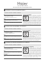
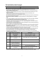
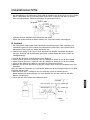
Questo prodotto contiene gas fluorurati ad effetto serra inclusi nel Protocollo
di Kyoto. Non liberare tali gas nell’atmosfera.
Tipo di refrigerante: R410A
Valore GWP*: 1975
*
GWP = potenziale di riscaldamento globale
Compilare con inchiostro indelebile,
• 1 la carica di refrigerante di fabbrica del prodotto
• 2 la quantità di refrigerante aggiuntiva nel campo e
• 1+2 la carica di refrigerante totale
sull’etichetta di carica del refrigerante fornita con il prodotto
L’etichetta compilata deve essere collocata in prossimità della portata di cari-
ca del prodotto (ad esempio, nell’interno del coperchio della valvola d’inter-
cettazione).
A contiene gas fluorurati ad effetto serra inclusi nel protocollo di Kyoto
B carica di refrigerante di fabbrica del prodotto: vedi targhetta con il nome
dell’unità
C quantità di refrigerante aggiuntiva nel campo
D carica di refrigerante totale
E unità esterna
F cilindro del refrigerante e collettore di carica
INFORMAZIONI IMPORTANTI SUL REFRIGERANTE UTILIZZATO
Haier Industrial Park, No.1 Haier Road, Qingdao, P.R.China
1
1+2=
kg
R410A
2
kg
2=
1=
B
C
D
FE
kg
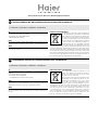
Contains fluorinated greenhouse gases
covered by the Kyoto Protocol
A
This product contains fluorinated greenhouse gases covered by the Kyoto
Protocol. Do not vent into the atmosphere.
Refrigerant type: R410A
GWP* value: 1975
*
GWP = global warming potential
Please fill in with indelible ink,
• 1 the factory refrigerant charge of the product
• 2 the additional refrigerant amount charged in the field and
• 1+2 the total refrigerant charge
on the refrigerant charge label supplied with the product.
The filled out label must be adhered in the proximity of the product charging
port (e.g. onto the inside of the stop valve cover).
A contains fluorinated greenhouse gases covered by the Kyoto Protocol
B factory refrigerant charge of the product: see unit name plate
C additional refrigerant amount charged in the field
D total refrigerant charge
E outdoor unit
F refrigerant cylinder and manifold for charging
IT
IMPORTANT INFORMATION REGARDING THE REFRIGERANT USED
EN
Ce produit contient des gaz à effet de serre fluorés encadrés par le protoco-
le de Kyoto. Ne pas laisser les gaz s’échapper dans l’atmosphère.
Type de réfrigérant: R410A
Valeur GWP*: 1975
*
GWP = potentiel de réchauffement global
Prière de compléter à l’encre indélébile,
• 1 la charge de réfrigérant d’usine du produit
• 2 la quantité de réfrigérant supplémentaire chargée sur place et
• 1+2 la charge de réfrigérant totale
sur l’étiquette de charge de réfrigérant fournie avec le produit.
L’étiquette complétée doit être apposée à proximité de l’orifice de recharge
du produit (par ex. à l’intérieur du couvercle de la vanne d’arrêt).
A contient des gaz à effet de serre fluorés encadrés par le protocole de
Kyoto
B charge de réfrigérant d’usine du produit: voir plaquette signalétique de
l’unité
C quantité de réfrigérant supplémentaire chargée sur place
D charge de réfrigérant totale
E unité extérieure
F cylindre de réfrigérant et collecteur de recharge
INFORMATION IMPORTANTE RELATIVE AU RÉFRIGÉRANT UTILISÉ
FR

Haier Industrial Park, No.1 Haier Road, Qingdao, P.R.China
1
1+2=
kg
R410A
2
kg
2=
1=
B
C
D
FE
kg
Contains fluorinated greenhouse gases
covered by the Kyoto Protocol
A
Dieses Produkt enthält fluorierte Treibhausgase, die durch das Kyoto-Proto-
koll abgedeckt werden. Lassen Sie Gase nicht in die Atmosphäre ab.
Kältemitteltyp: R410A
GWP* Wert: 1975
*
GWP = Treibhauspotential
Bitte füllen Sie am Kältemittelbefülletikett, das im Lieferumfang des Gerätes
enthalten ist, mit abriebfester Tinte wie folgt aus:
• 1 die werkseitige Kältemittelbefüllung des Produktes
• 2 die am Montageort befüllte zusätzliche Kältemittelmenge und
• 1+2 die gesamte Kältemittelbefüllung
Das ausgefüllte Etikett muss in der Nähe der Kältemittel-Einfüllöffnung ange-
hängt werden (z. B. auf der Innenseite der Absperrventilabdeckung).
A Enthält fluorierte Treibhausgase, die durch das Kyoto-ProtoKoll abge-
deckt werden
B werkseitige Kältemittelbefüllung des Produktes: siehe Typenschild der
Einheit
C zusätzliche am Montageort befüllen Kältemittelmenge
D gesamte Kältemittelbefüllung
E Außeneinheit
F Kältemittelzylinder und Sammelleitung für die Befüllung
WICHTIGE INFORMATIONEN HINSICHTLICH DES VERWENDETEN KÄLTEMITTELS
DE
Este producto contiene los gases fluorados de efecto invernadora regulados
por el Protocolo de Kioto. No vierta gases a la atmósfera.
Tipo de refrigerante: R410A
Valor GWP*: 1975
*
GWP = Potencial de calentamiento global
Rellene con tinta indeleble,
• 1 la carga de refrigerante de fábrica del producto
• 2 la cantidad adicional de refrigerante cargado en campo y
• 1+2 la carga total de refrigerante
En la etiqueta de carga de refrigerante suministrada con el producto.
La etiqueta rellenada debe pegarse cerca de la conexión de carga del pro-
ducto (p.ej. en el interior de la cubierta de la válvula de tope).
A Contiene los gases fluorados de efecto invernadora regulados por el
Protocolo de Kioto
B Carga de refrigerante de fábrica del producto: véase placa de especifi-
caciones técnicas de la unidad
C Cantidad adicional de refrigerante cargado en campo
D Carga total de refrigerante
E Unidad exterior
F Cilindro del refrigerante y dosificador de carga
INFORMACIÓN IMPORTANTE EN RELACIÓN AL REFRIGERANTE UTILIZADO
ES

FZ8>8KMJWF
FZ:>8KNJWF
FZ:>SKNJWF
FZ<6SKNJWF
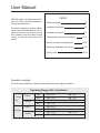
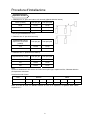
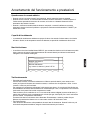
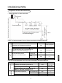
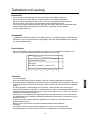
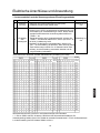
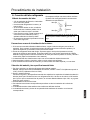
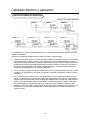
Ulease read this manual carefully before using
Peep this operation manual for future reference

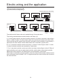
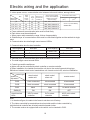
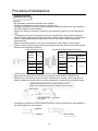
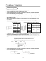
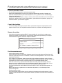
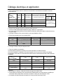
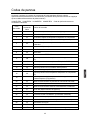
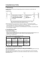
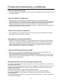
RW[NN3X adopts +simultaneous control+
type2 all indoors should be heating or
cooling simultaneously4
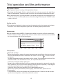
Yo use the air conditioner normally2 please perform as to the below conditions4
Yo protect compressor2 before startup2
the unit should be electrified for over 78
hours4 Nf the unit is not used for a long
time2 please cut off the power to save
energy2 or the unit will consume the
power4
cooling
dry
heating
indoor
outdoor
indoor
outdoor
max4
min4
max4
min4
max4
min4
max4
min4
IG@ 98
\G@ 7;
IG@ 7>
IG@ :9
IG@ 3;
IG@ 8=
IG@ 7;
IG@ 87
IG@ 37;
\G@ 89
\G@ 7:
\G@ 8<
O
O
O
O
O
O
O
O
O
O
O
O
.C9D5F=A; 05A;9 B: z=D |BA8=F=BA9D
738
93:
;379
7:37;
7<388
8938:
8;38<
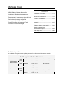
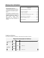
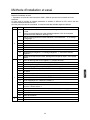
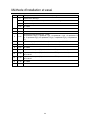
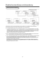
Zser Ranual
WZY[XY[
Xafety precaution
Nnstallation instruction
Nnstallation procedure
Yrial operation and the performance
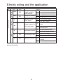
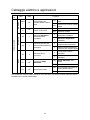
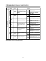
Jlectric wiring and the application
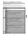
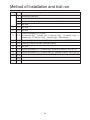
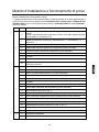
Rethod of installation and trial run
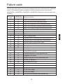
Kailure code
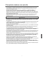
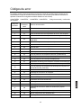
Tperation condition@

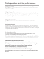
Nf the air conditioner is transferred to the others2 this manual should be tranferred together4
Yhe installation or the maintenance should be performed by the authorized agency4 Tr the
non3specialized operation will cause water leakage2 electric shock or fire etc accidents4
Yhe installation should be executed as per the manual2 or the faulty installation will cause
water leakage2 electric shock or fire etc accidents4
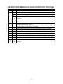
Ulease install the unit at the space which can bear the weight4 Tr the unit will drop down to
cause the human injury4
Yhe installation should defend against the typhoon2 and the earthquake etc4 Fbnormal
installation will cause the unit fall down4
Zse the correct cable and make reliable earthing4 Kix the terminal firmly and the loose
connection will cause heating or fire etc accident4
Yhe wiring should be in shape and can not be raised4 Ge earthed firmly and can not be clipped
by the electric box cover or the other plate4 Yhe incorrect installation will cause heating or fire4
\hen setting or transferring the unit2 there should not be other air into the refrigerant system
except for W:76F4 Yhe gas mixture will cause the abnormal high pressure which will cause
break or human injury etc accidents4
\hen installation2 please use the accessories with the unit or the special parts2 or it will cause
water leakage2 electric shock2 fire2 refrigerant leakage etc accidents4
Ion-t lead the water drainage pipe into the drainage groove with the poisonous gas2 such as
sulphur4 Tr the poisonous gas will enter indoor4
Nn installation or after installation2 please confirm if there is refriegerant leakage2 please take
measures for ventilation4 Yhe refrigerant will cause poisonous gas as meeting fire4
Ion-t install the unit at the place where there may be flammable gas leakage4 Nn case the gas
leaks and gather around the unit2 it will cause fire4
Yhe drainage pipe should be installed as per the manual to confirm the fluent drainage4 Flso
take measures for heat insulation against dew drop4 Nncorrect water pipe installation will cause
water leakage even and make the things wet4
Kor the liquid pipe and the gas pipe2 take measures for heat insulation too4 Nf there is no heat
insulation2 the dew drop will wet the things4
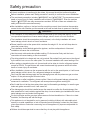
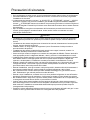
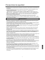
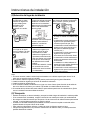
Gefore installation2 please read +Xafety precaution+ carefully to confirm the correct installation4
Yhe mentioned precaustion includes +
L
\FWSNSL+ and +
L
HFZYNTS+4 Yhe precausion caused
death or heavy injury for faulty installation will be listed in +
L
\FWSNSL+4 Jven the cautions
listed in +
L
HFZYNTS+ also may cause serious accident4 Xo both of them are related to the
safety2 and should be executed severely4
Ffter installation2 perform a trial and confirm everything normal2 then introduce the operation
manual to the user4 Gesides2 put the manual to the user and ask them to preserve it carefully4
7
Yhis appliance is not intended for use by persons .including children/ with reducedphysical2
sensory or mental capabilities2 or lack of experience and knowledge2 unless they have been
given supervision or instruction concerning use of the appliance by a person responsible for
their safety4
Hhildren should be supervised to ensure that they do not play with the appliance4
L
\FWSNSL
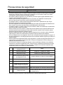
Xafety precaution

L
8
HFZYNTS
Jxecute earthing for the unit4 Gut the earthing wire can not be connected to the gas pipe2 water
pipe2 lightening rod or the telephone earthing wire4 Nmproper earthing will cause electric shock4
Ion-t install the unit at the place where leaks the flammable gas4 Tr it will cause fire4
Jxecute the water drainage pipe according to the manual2 improper installation will cause water
leakage to wet the family things4
Yhe outdoor fan can not face to the flower or the other vegetable2 or the blowing gas will make
the flower dried up4
Ulease ensure the maintenance room2 if not2 it will cause the maintenance person damaged4
\hen installing the unit on the roof or the other high place2 to prevent the person falling down2
please set the fixed ladder and the railing at the passage4
Zse the two3end spanner2 and fasten the nut at proper torque4 Ion-t fasten the nut excessively
against the flared setion broken4 Tr it will cause refrigerant leakage and lack of oxygen4
Yake measures for heat insulation to the refrigerant pipe2 or there will be water leakage or dew
drop to wet the family things4
Ffter finishing the refrigerant pipe2 make leakage test by charging the nitrogen4 Nn case the
refrigerant leaks in a small room and exceeds the limited concentration2 it will cause lack of
oxygen4
Ion-t use the other refrigerant except for W:76F4 Yhe W:76F pressure is 74< times higher than
W88 pressure4 Yhe refrigerant W:76F tank is marked with pink sign4
Fgainst charging different refrigerant2 we changed the stop valve diameter of the W:76F unit4
Yo enhance the compression consistance2 we also changed the flared pipe dimension4 Urepare
the W:76F specially tools according to the below table4
\hen charging refrigerant2 the refrigerant must be taken out as liquid state from the tank4
W:76F specially tool
gauge manifold
torque spanner
a
b
c
d
e
f
g
h
range@MUz:4;RUa2QUz8RUa
pressure@MU@;49RUa2QU@94;RUa
can not use the measurable charging tank
must be with reverse stop valve
can not use freon leakage detector2but the
Me detector
Wemarks
charge hose
electronic balance for
charging W:76F
flare tool
copper pipe gauge for
adjusting projecting margin
vacuum pump adapter
leakage detector
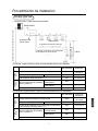
Xafety precaution

9
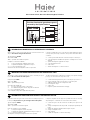
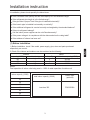
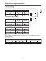
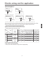
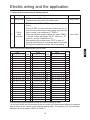
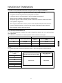
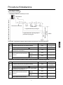
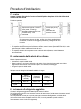
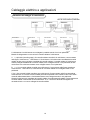
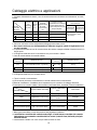
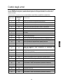
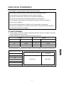
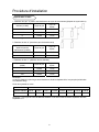
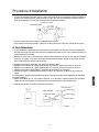
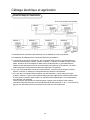
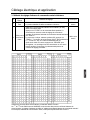
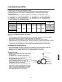
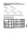
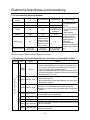
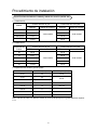
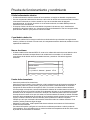
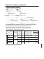
Nf the connected units quantity and the total capacity is in the allowable rangeE
Nf the refrigerant pipe length is in the limited rangeE
Nf the pipe size is properE Fnd if the pipe is installed horizontallyE
Nf the branch pipe is installed horinzontally or verticallyE
Nf the additional refrigerant is counted correctly and weighed by the standard balanceE
Nf there is refrigerant leakageE
Nf all the indoor power supplies can be on5off simultaneouslyE
Nf the power voltage is in compliance with the data marked on the rating labelE
Nf the address of indoors has been setE
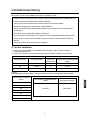
indoor
capacity .766\/
outdoor
combination type indoor Vty total indoor capacity .766\/
>6
7;6
7>6
single
single
single
;
>
?
:6376:
=;37?;
?6389:
indoor capacity .766\/
88
8>
9<
:6
:;
;<
=7
KVL3G99;F
total indoor capacity .766\/
less than 99;
branch pipe
.optional/
Sotice@
Yotal capacities of indoor units being used M 766, of rated capacities of outdoor unit
Nnstallation instruction
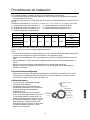
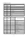
Nn installation2 please check specially the below items@
puq {9:BD9 =AEF5??5F=BA
7/ Gefore installation2 check if the model2 power supply2 pipe2 wires and parts purchased
respectively are correct4
8/ Hheck if the indoors and outdoors can be combined as the following4

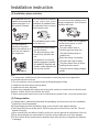
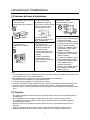
:
Fir3conditioner can-t be
installed in the place with
inflammable gas4 Tr it
will cause fire hazard4
Yhe unit should be installed at the
strong enough place4 Tr it will cause
vibration and noise4
Yhe unit should be
installed at the place
where the cold5hot air or
noise will not interfere
the neighbours4
Yhe unit is better not be installed
at the below places2 or it will
cause damage4
Yhe place where there is
corrosive gas .spa area etc/4
Yhe place blowing salty air
.seaside etc/4
Jxsits the strong coal smoke4
Yhe place with high humidity4
Yhe place where there is device
emitting Mertzian waves4
Yhe place where voltage changes
greatly4
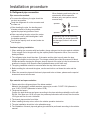
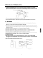
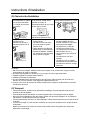
Nn transportation2 please don-t dismantle the packaging2 and move the unit to the installation
location as closely as possible4
Nf the packaging must be dismantled2 hang up the unit with rope against damage4
Ion-t hang the unit only at two points4 \hen hanging the unit2 don-t sit on the unit4 Yhe unit
should be upright4
\hen removing the unit with the forklift2 put the fork into the special hole at bottom of the unit4
\hen being hanged2 the rope should be : pieces of steel cable with over <mm diameter4
Uut the cushion at the contact section between steel cable and the unit against the distortion
or damage4
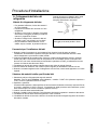
pwq 2D5AECBDF5F=BA
Yhe place where the water
can flow fluently4
Yhe place where no other
heat source will affect the
unit4
Uay attention to the snow
against clogging the outdoor4
Nn installation2 install the anti3
vibration rubber between the
unit and the bracket4
Nnstallation instruction
Sote@
74 Nn snowy area2 install the unit under the bracket or the snow3proof cover against the
accumulative snow on the unit4
84 Io not install the unit at the place where the flammable gas will leak4
94 Nnstall the unit at the strong enough place4
:4 Nnstall the unit at the flat place4
;4 \hen being installed at the place with strong wind2 set the air outlet of the unit and the wind
direction vertical4 Flso fix the unit with the screw4
<4 \hen opening the electric box cover for maintenance2 please fix the cover with screw firmly4
pvq ,AEF5??5F=BA C?579 E9?97F=BA
Yhe unit should be installed
at the place with good
ventilation4 So obstacle at the
air inlet5outlet4 Fnd no strong
wind blows the unit4
Yhe installation space refers
to the latter info4

;
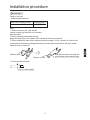
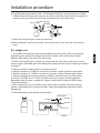
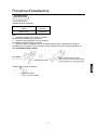
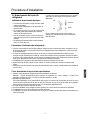
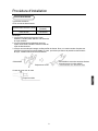
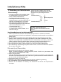
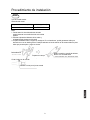
zs 09:D=;9D5AF C=C9 7BAA97F=BA
\hen fastening and loosing the nut2
operate with double spanners2
because only one spanner cannot
execute firmly4
Nf threading the nut as not aiming
at the center2 the screw thread will
be damaged2 further it will cause
leakage4
spanner
spanner
connector
nut
Yo ensure the efficiency2 the pipe should be
as short as possible4
Iaub the refrigerant oil on the connector and
the flare nut4
\hen bending the pipe2 the bending semi3
diameter should be as large as possible
against the pipe being broken or bent4
\hen connecting the pipe2 aim at the center
to thread the nut by hand and tighten it with
the double spanners4
Ion-t let the impurity such as sand2 water etc
into the pipe4
/=C9 7BAA97F=BA @9F<B8y
74 \hen welding the connector with hard solder2 charge nitrogen into the pipe against oxidation4
Tr the oxygen film in the pipe will clog the capillary and the expansion valve2 even caue the
deathy accident4
84 Yhe refrigerant pipe should be clean4 Nf the water and the other impurity enter the pipe2
charge the nitrogen to clean the pipe4 Yhe nitrogen should flow under the pressure of about
64;Rpa and when charging the nitrogen2 stop up the end of the pipe by hand to enhance the
pressure in the pipe2 then loose the hand .meanwhile stop up the other end/4
94 Yhe piping installation should be executed after the stop valves are closed4
:4 Gefore welding the valve and the pipes2 use the wet cloth to cool down the valve and the
pipes4
;4 \hen the connection pipe and the branch pipe need to be cut down2 please use the special
shears and cannot use the saw4
|5GF=BAE =A C=C=A; =AEF5??5F=BAy
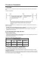
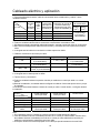
/=C9 @5F9D=5? 5A8 EC97E E9?97F=BA
74 Ulease select the refrigerant pipe of the below material4
Raterial@ the phosphoric oxidize seamless copper pipe2 model@ H7886Y3758M .diameter is
over 7?46;/A H7886Y36.diameter is below 7;4>>/4
84 Yhickness and specs@
Honfirm the pipe thickness and specs according to the pipe selection method.the unit is with
W:76F2 if the pipe over 7?46; is 63type2 the pressure preservation will be bad2 thus it must be
758M type and over the min4 thickness4
94 Yhe branch pipe must be from Maier4
:4 \hen installing the stop valve2 refer to the relative operation instruction4
;4 Yhe pipe installation should be in the allowable range4
<4 Yhe installation of branch pipe and gather pipe should be performed according to the relative
manual4
Nnstallation procedure

<
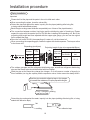
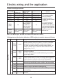
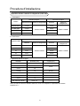
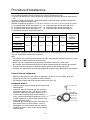
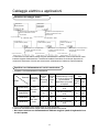
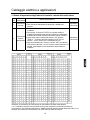
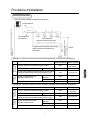
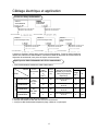
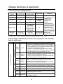
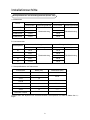
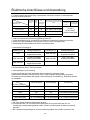
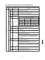
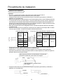
/=C9 EC97=:=75F=BAy
c
aa
b
b
aa
74 Uipe |a} diameter .between indoor and branch pipe/ .depends on indoor pipe/
88{8>
9<{;<
=7
?4;80 <49;
784= <49;
7;4>> ?4;8
Nndoor .x
766\/
Las pipe Qiquid pipe
84 Uipe |b} diameter .between branch pipes/
B778 7;4>>
7?46;778M]B89:
?4;8
Yotal indoor capacity after
the branch pipe .x766\/
?4;8
Las pipe Qiquid pipe
Sote@
\hen the distance from outdoor to the longest indoor is over 96m2 the main pipe should be the
enlarged diameter4
94 Uipe |c} diameter . outdoor pipe diameter/
Tutdoor capacity.766\/
>6
7;6
7>6
7;4>>
7?46;
7?46; ?4;8
Las pipe Qiquid pipe
?4;8
?4;8
Hopper pipe selection@
Sote@ Nf the copper pipe with outer diameter 7?46; is coil pipe2 the thickness should be over 7474
<49; ?4;8 784= 7;4>>
64> 64> 746 746
7?46; 88488 8;48: 8>4;>
746 747 748 74:
softness Malf3hardnesshardness
Tuter diameter
Rin4 thickness
0FX6?8RHJWF-s gas pipe is
784=
Nnstallation procedure

=
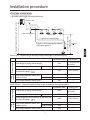
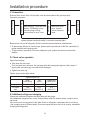
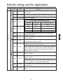
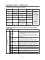
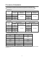
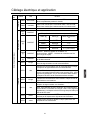
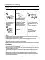
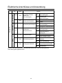
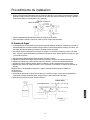
-BA; C=C9 5A8 <=;< 8DBC
74 Fllowable pipe length and height difference
Qength of the longest piping after the
first branch piping Q
g
Q
:
hi
Qength of the longest piping Q
Q
8
Q
7
h 76m
f
Q
9
ab
c
d
e
Tutdoor unit
Kirst branch piping
Nndoor unit
Irop height between indoor and outdoor units
Irop height between
indoor units
Uiping length
Irop
height
\\
\\
\\
Uiping part
766m
=6m
96m
96m
86m
76m
Uermissible value
Qongest piping Q
Uiping length of indoor unit which is furthest to the
first branch piping Q
Irop height between indoor and
outdoor unit M
Irop height between indoor units h
Yotal length of piping .actual length/
Fctual length
Zp outdoor
Znder outdoor
FZ:>{<6 type@ Raximal length and drop height permissible of refrigerant piping
Q81Q91Q:1e
Q71Q81Q91Q:1a
1b1c1d1e
Q71Q81Q91Q:1e
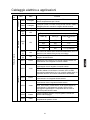
Uiping length
Irop
height
\\
\\
\\
Uiping part
;6m
9;m
7;m
96m
86m
76m
Uermissible value
Qongest piping Q
Uiping length of indoor unit which is furthest to the
first branch piping Q
Irop height between indoor and
outdoor unit M
Irop height between indoor units h
Yotal length of piping .actual length/
Fctual length
Zp outdoor
Znder outdoor
FZ8>8 type@ Raximal length and drop height permissible of refrigerant piping
Q81Q91Q:1e
Q71Q81Q91Q:1a
1b1c1d1e
Q71Q81Q91Q:1e
Nnstallation procedure

>
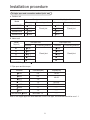
3A=F C=C9 EC97 5A8 7BAA97F=BA @9F<B8 pGA=Fy @@q
F4 Tutdoor unit
Rodel
7;4>>
7?46;
7?46;
Klared joint
?4;8
?4;8
?4;8
Klared joint
Las pipe side Qiquid pipe side
Iiameter Honnecting method Iiameter Honnecting method
FZ8>8KMJWF
FZ:>SKNJWF
FZ<6SKNJWF
G4 Nndoor unit
Las pipe side
Rodel
Hapacity
784=
7;4>>
Klared joint
Qiquid pipe side
Iiameter
Honnecting method
Iiameter
Honnecting method
8:
7>
7<
78
6?
Klared joint
?4;8
784=
784=
<49;
?4;8
<49;
<49;
<49;
H4 Uipe spec and the torque
Sot less than
8>4;>
diameter Yhickness.mm/
64>
64>
746
746
746
748
Yorque.S4m/
7<{86
:6{;6
?6{786
766{7:6
\\
<49;
?4;8
784=
7;4>>
7?46;
8;4:
Rore than 74:
747
88488
Sote@ Nf the copper pipe with outer diameter 7?46; is coil pipe2 the thickness should be over 7474
\\
\\
7?46; ?4;8
FZ:>8KNJWF
FX6?8RHJWF-s gas pipe is
784=
Nnstallation procedure

?
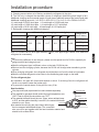
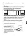
Tutdoor unit type
{D5A7< C=C9
total indoor capacity.766\/ model.optional/
less than 99; KVL3G99;F
Granch pipe selection@
Sote@
74 \hen connecting the pipe and the
outdoor2 please pay attention to the outdoor
pipe dimension4
84 \hen adjusting the diameter among
pipes and among the units2 please must execute at the branch pipe side4
94 \hen welding with hard solder2 please must blow nitrogen4 Nf not2 a number of oxide will be
produced and cause heavy damage4Gesides2to prevent water and dust into the pipe2 please
make the brim as outer roll4
Hut off pipe with the cutter
Hut off at the middle
Fdhesive side
Urepare on field
Xeal the connection and wrap the
heat insulator with adhesive tape
Nnstallation procedure

76
/=C=A; =AEF5??5F=BA
Ulease don-t let the pipe and the parts in the unit collide each other4
Yhe connection between outdoor liquid pipe and the distributing pipe is flared type4 Ulease
expand the pipe with the special tool for W:76F after installing the expanding nut4 Gut if the
projecting pipe length has been adjusted with the copper pipe gauge2 you can use the original
tool to expand the pipe4
Xince the unit is with W:76F2 the expanding oil is ester oil2 not the mineral oil4
\hen connecting the pipes2 close the valves fully4
Urotect the pipe end against the water2 impurity into the pipes .welding after being flat2
or being sealed with adhesive tape/4
Gend the pipe as large semi3diameter as possible.over : times of the pipe diameter/4
\hen connecting the expanding pipe2 fasten the pipes with double3spanner4 Yhe torque refers
to the former info4
Nmportant
F
F
6
364:
<49;
?4;8
784=
7;4>>
?47
7948
7<4<
7?4=
Jxpanding [email protected]/
G
pipe outer
diameter
<49;
?4;8
784=
7;4>>
when it is hard pipe
6364; 746374;
pipe outer
diameter
special tool
for W:76F
the former
tool
welding
adhesive tape
flat
Urotect the pipe end against the water2 impurity into the pipes .welding after being flat2 or being
sealed with adhesive tape/4
Xeal the pipe end with adhesive tape or the stopper
to increase the resistance2 fill up the pipe with nitrogen4
BS8D
taping
Tnly nitrogen
gas can be used
brazing
Yhe outdoor gas pipe and the refrigerant distributing pipe2 as well the refrigerant distributing
pipe and the branch pipe should be welded with hard solder4
\eld the pipe at the same time charge the nitrogen4 Tr it will cause a number of impurity .a
film of oxidation/ to clog the capillary and the expansion valve2 further cause the deadly failure4
Nnstallation procedure

77
source valve
7st side
8nd side
hand
648RUa
Yhe refrigerant pipe should be clean4 Yhe nitrogen should flow under the pressure of about
648Rpa and when charging the nitrogen2 stop up the end of the pipe by hand to enhance the
pressure in the pipe2 then loose the hand .meanwhile stop up the other end/4
\hen welding the valve and the pipes2 use the wet cloth to cool down the valve and the
pipes4
\hen connecting the pipes2 close the valves fully4
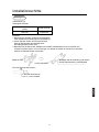
{s -95>5;9 F9EF
74 Yhe outdoor unit has been executed the leakage test in the factory4 Ffter connecting the
distributing pipe2 execute the leakage test from the outdoor check valve and the indoor4
Gesides2 while testing2 the valves should be close4
84 Wefer to the below figure to charge the nitrogen into the unit to take a test4 Sever use the
chlorin2 oxygen2 flammable gas in the leakage test4 Fpply pressure both on the gas pipe and the
liquid pipe4
94 Fpply the pressure step by step to the target pressure4
a4 Fpply the pressure to 64;RUa for more than ; minutes2 confirm if pressure goes down4
b4 Fpply the pressure to 74;RUa for more than ; minutes2 confirm if pressure goes down4
c4 Fpply the pressure to the target pressure .:46RUa/2 record the temp4 and the pressure4
d4 Qeave it at :46RUa for over 7 day2 if pressure does not go down2 the test is passed4
Reanwhile2 when the temp4 changes for 7degree2 pressure will change 6467RUa as well4
Horrect the pressure4
e4 Ffter confirmation of a{d2 if pressure goes down2 there is leakage4 Hheck the brazing
position2 flared position by laying on the soap4 modify the leakage point and take another
leakage test4
:4 Ffter leakage test2 must execute the evacuation4
gauge manifold
Qo
Mi
Qo handle
Mi handle
nitrogen
to indoor
outdoor
gas pipe
check valve
gas pipe
check hole
Nnstallation procedure

78
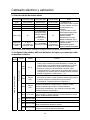
|s ~H57G5F=BA
Jvacute at the check valve of liquid stop valve and both sides of the gas stop valve4
Yo prevent the different oil into the pipe2 please use the special tool for W:76F2 especially for
gauge manifold and charging hose4
Yo prevent the compressor oil into the refrigerant cycle2 please use the anti3counter3flow
adapter4
Gecause the unit is with refrigerant W:76F2 the below issues should be paid attention@
Yighten torque as the table below@
less than =
=4>;
.RF]7;4=/
less than 96
8?4:
.RF]9?48/
79
>4>
.RF]7:4=/
shaft
.valve body/
cap
.cover/
Y3shape nut
.check joint/
Yighten torque S4m
for gas pipe
for liquid
pipe
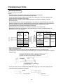
}s |<97> H5?H9 BC9D5F=BA
Tpen5close method@
Yake down the valve cap4
Yurn the liquid stop valve and the gas stop valve with hexangular spanner until it stops4 Nf
opening the valve strongly2 the valve will be damaged4
Yighten the valve cap4
Tperation procedure@
leakage test passed
evacuation begins
evacuation ends
check vacuum
charge refrigerant
after reaching 3767PUa or less
.below 3=;;mmMg/2 let the
vacuum pump running
continuously for over 7hour4
leave it for over 7
hour2 vacuum
pointer does not
arise4
if vacuum pointer arises2 it shows there is water or leakage in the
system2 please check and modify it2 and then evacuate again4
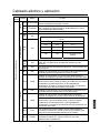
~s z88=F=BA5? D9:D=;9D5AF 7<5D;=A;
Hharge the additional refrigerant as liquid state with the gauge4
Nf the additional refrigerant can not be charged totally when the outdoor stops2 charge it at the
trial mode4
Nf the unit runs for a long period in the state of lack of refrigerant2 compressor will occur failure4
. the charging must be finished within 96 minutes especially when the unit is running2 menawhile
charging the refrigerant/4
Nnstallation procedure
La page charge ...
La page charge ...
La page charge ...
La page charge ...
La page charge ...
La page charge ...
La page charge ...
La page charge ...
La page charge ...
La page charge ...
La page charge ...
La page charge ...
La page charge ...
La page charge ...
La page charge ...
La page charge ...
La page charge ...
La page charge ...
La page charge ...
La page charge ...
La page charge ...
La page charge ...
La page charge ...
La page charge ...
La page charge ...
La page charge ...
La page charge ...
La page charge ...
La page charge ...
La page charge ...
La page charge ...
La page charge ...
La page charge ...
La page charge ...
La page charge ...
La page charge ...
La page charge ...
La page charge ...
La page charge ...
La page charge ...
La page charge ...
La page charge ...
La page charge ...
La page charge ...
La page charge ...
La page charge ...
La page charge ...
La page charge ...
La page charge ...
La page charge ...
La page charge ...
La page charge ...
La page charge ...
La page charge ...
La page charge ...
La page charge ...
La page charge ...
La page charge ...
La page charge ...
La page charge ...
La page charge ...
La page charge ...
La page charge ...
La page charge ...
La page charge ...
La page charge ...
La page charge ...
La page charge ...
La page charge ...
La page charge ...
La page charge ...
La page charge ...
La page charge ...
La page charge ...
La page charge ...
La page charge ...
La page charge ...
La page charge ...
La page charge ...
La page charge ...
La page charge ...
La page charge ...
La page charge ...
La page charge ...
La page charge ...
La page charge ...
La page charge ...
La page charge ...
La page charge ...
La page charge ...
La page charge ...
La page charge ...
La page charge ...
La page charge ...
La page charge ...
La page charge ...
La page charge ...
La page charge ...
La page charge ...
La page charge ...
La page charge ...
La page charge ...
La page charge ...
La page charge ...
La page charge ...
La page charge ...
La page charge ...
La page charge ...
La page charge ...
La page charge ...
La page charge ...
La page charge ...
La page charge ...
La page charge ...
La page charge ...
La page charge ...
La page charge ...
La page charge ...
La page charge ...
La page charge ...
La page charge ...
La page charge ...
La page charge ...
La page charge ...
La page charge ...
La page charge ...
-
 1
1
-
 2
2
-
 3
3
-
 4
4
-
 5
5
-
 6
6
-
 7
7
-
 8
8
-
 9
9
-
 10
10
-
 11
11
-
 12
12
-
 13
13
-
 14
14
-
 15
15
-
 16
16
-
 17
17
-
 18
18
-
 19
19
-
 20
20
-
 21
21
-
 22
22
-
 23
23
-
 24
24
-
 25
25
-
 26
26
-
 27
27
-
 28
28
-
 29
29
-
 30
30
-
 31
31
-
 32
32
-
 33
33
-
 34
34
-
 35
35
-
 36
36
-
 37
37
-
 38
38
-
 39
39
-
 40
40
-
 41
41
-
 42
42
-
 43
43
-
 44
44
-
 45
45
-
 46
46
-
 47
47
-
 48
48
-
 49
49
-
 50
50
-
 51
51
-
 52
52
-
 53
53
-
 54
54
-
 55
55
-
 56
56
-
 57
57
-
 58
58
-
 59
59
-
 60
60
-
 61
61
-
 62
62
-
 63
63
-
 64
64
-
 65
65
-
 66
66
-
 67
67
-
 68
68
-
 69
69
-
 70
70
-
 71
71
-
 72
72
-
 73
73
-
 74
74
-
 75
75
-
 76
76
-
 77
77
-
 78
78
-
 79
79
-
 80
80
-
 81
81
-
 82
82
-
 83
83
-
 84
84
-
 85
85
-
 86
86
-
 87
87
-
 88
88
-
 89
89
-
 90
90
-
 91
91
-
 92
92
-
 93
93
-
 94
94
-
 95
95
-
 96
96
-
 97
97
-
 98
98
-
 99
99
-
 100
100
-
 101
101
-
 102
102
-
 103
103
-
 104
104
-
 105
105
-
 106
106
-
 107
107
-
 108
108
-
 109
109
-
 110
110
-
 111
111
-
 112
112
-
 113
113
-
 114
114
-
 115
115
-
 116
116
-
 117
117
-
 118
118
-
 119
119
-
 120
120
-
 121
121
-
 122
122
-
 123
123
-
 124
124
-
 125
125
-
 126
126
-
 127
127
-
 128
128
-
 129
129
-
 130
130
-
 131
131
-
 132
132
-
 133
133
-
 134
134
-
 135
135
-
 136
136
-
 137
137
-
 138
138
-
 139
139
-
 140
140
-
 141
141
-
 142
142
-
 143
143
-
 144
144
-
 145
145
-
 146
146


Haier AU48NFIERA Guide d'installation
- Catégorie
- Climatiseurs split-system
- Taper
- Guide d'installation
- Ce manuel convient également à
dans d''autres langues
- italiano: Haier AU48NFIERA Guida d'installazione
- español: Haier AU48NFIERA Guía de instalación
- Deutsch: Haier AU48NFIERA Installationsanleitung
Documents connexes
-
Haier AD302MMERA Mode d'emploi
-
Haier 001051 Manuel utilisateur
-
-
-
-
-
-
-
Haier 2U18FS2ERA Le manuel du propriétaire
-
Haier AC182MCERA Mode d'emploi