
Need help? Visit Sauder.com to view video assembly tips or chat with a live rep.
Prefer the phone? Call 1-800-523-3987.
Share your journey!
sauder.com
NOTE: THIS INSTRUCTION
BOOKLET CONTAINS IMPORTANT
SAFETY INFORMATION.
PLEASE READ AND KEEP FOR
FUTURE REFERENCE.
Enlish p 1-24
Français p 25-28
Español p 29-32
Lot # 528691 04/22/19
Purchased: __________________
Be sure to ive us a rin before
makin any returns. 1-800-523-3987
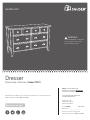
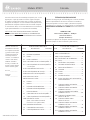
Dresser
Shoal Creek Collection | Model 411201
WARNING
CHOKING HAZARD - Small Parts
Not for children under 3 years.
Adult assembly required.

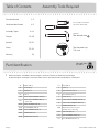
Table of Contents Assembly Tools Required
Part Identifi cation
Hardware Identifi cation
Assembly Steps
Français
Español
Safety
Warranty
Hammer
Not actual size
No. 2 Phillips Screwdriver
Tip Shown Actual Size
Skip the power trip.
This time.
2-3
4-5
6-24
25-28
29-32
33-34
35
411201 www.sauder.com/servicesPae 2
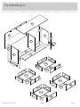
å While not all parts are labeled, some of the parts will have a label or an inked letter on the ede
to help distinuish similar parts from each other. Use this part identifi cation to help identify similar parts.
Now you know
our ABCs.
Part Identifi cation
A2 RIGHT END (1)
B2 LEFT END (1)
C2 UPRIGHT (1)
D2 TOP (1)
D10 SMALL RIGHT DRAWER SIDE (2)
D11
SMALL LEFT DRAWER SIDE (2)
- 1 with label
D132 RIGHT DRAWER SIDE (4)
D138 LEFT DRAWER SIDE (4)
D166 SMALL DRAWER BACK (2)
D167 DRAWER BACK (4)
D975 DRAWER BOTTOM (6)
E2 BOTTOM (2)
F BACK (1)
G RIGHT FRONT LEG (1)
H LEFT FRONT LEG (1)
I REAR LEG (2)
K2 SMALL RIGHT DRAWER FRONT (1)
L2 SMALL LEFT DRAWER FRONT (1)
M65
DRAWER BRACE (6)
(Hidden part usin recycled
material. Color may vary.)
M73 END MOLDING (2)
Q2 RIGHT DRAWER FRONT (2)
R2 LEFT DRAWER FRONT (2)

Part Identifi cation
411201www.sauder.com/services
Pae 3
A2
B2
C2
D2
E2
F
G
H
I
K2
L2
M73
Q2
R2
D10
D11
D132
D138
D166
D167
D975
D975
D975
D975
D10
D11
D166
D167 D132
D138
I
M73
E2
M65
M65
M65
M65

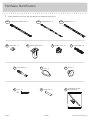
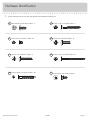
Hardware Identifi cation
å Screws are shown actual size. You may receive extra hardware with your unit.
411201 www.sauder.com/servicesPae 4
ADJUSTABLE FOOT - 1
34E
METAL PIN - 4
1R
PULL - 8
31K
10A
SLIDE CAM - 12
CAM SCREW - 12
8F
KNOB - 4
32K
NAIL - 47
1N
HIDDEN CAM - 22
1F
CAM DOWEL - 10
2F
40DA
UNIVERSAL CABINET RAIL - 12
40DC
DRAWER RIGHT - 6
40DD
DRAWER LEFT - 6
FURNITURE TIPPING
RESTRAINT KIT - 1
97

Hardware Identifi cation
å Screws are shown actual size. You may receive extra hardware with your unit.
411201www.sauder.com/services
Pae 5
BLACK 1-1/8" MACHINE SCREW - 4
21S
SILVER 3/4" MACHINE SCREW - 16
20S
BLACK 9/16" LARGE HEAD SCREW - 4
1S
BLACK 1-7/8" FLAT HEAD SCREW - 2
2S
BLACK 2-1/4" FLAT HEAD SCREW - 6
26S
3S
GOLD 5/16" FLAT HEAD SCREW - 48
BLACK 9/16" FLAT HEAD SCREW - 4
32S30S
BLACK 1-9/16" FLAT HEAD SCREW - 30

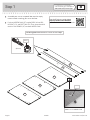
Step 1
Look for this icon. It means a
video assembly tip is available at
www.sauder.com/services/tips
411201 www.sauder.com/servicesPae 6
A2
B2
C2
E2
E2
å
Assemble your unit on a carpeted fl oor or on the empty
carton to avoid scratchin your unit or the fl oor.
å
Push ten HIDDEN CAMS (1F) into the ENDS (A2 and B2),
UPRIGHT (C2), and BOTTOMS (E2). Then, insert the metal
end of a CAM DOWEL (2F) into each HIDDEN CAM.
Do not tihten the HIDDEN CAMS in this step.
Insert the metal end of the CAM
DOWEL into the HIDDEN CAM.
Arrow
(10 used)
Arrow
1F
2F
Scan this QR code or go to this address:
http://qr.sauder.com/?ID=2558
to watch a video on how to assemble your unit.

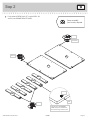
Step 2
411201www.sauder.com/services
Pae 7
M65
M65
M65
M65
M65
M65
å
Push twelve HIDDEN CAMS (1F) into the ENDS (A2
and B2) and DRAWER BRACES (M65).
Arrow
1F
1F
Arrow
(12 used)
Arrow
1F
Arrow
The arrow in the HIDDEN
CAM must point toward the
hole in the ede of the board.
Hole
A2
B2
Some assembly
(and snacks) required.

Step 3
411201 www.sauder.com/servicesPae 8
G
H
8F
(12 used)
K2
L2
R2
R2
Q2
Q2
å
Turn twelve CAM SCREWS (8F) into the FRONT LEGS (G
and H) and DRAWER FRONTS (K2, L2, Q2, and R2).

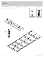
Step 4
411201www.sauder.com/services
Pae 9
A2
B2
M73
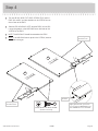
å
Turn four BLACK 9/16" FLAT HEAD SCREWS (32S) into the
ENDS (A2 and B2) until the shoulders of the SCREWS rest on
the surfaces of the ENDS.
å
Slide the END MOLDINGS (M73) onto the ENDS (A2 and B2).
Line up the rooves in the MOLDINGS over the heads of the
SCREWS in the ENDS.
å
NOTE: The MOLDINGS should be centered on the ENDS.
å
NOTE: If the MOLDING comes up o of the SCREWS, remove
it and slide it on aain.
These edes
should be even.
These edes
should be even.
BLACK 9/16" FLAT HEAD SCREW
(4 used in this step)
32S
Surface without
HIDDEN CAMS
Surface without
HIDDEN CAMS
Shoulder
Apply pressure with your hands
as you uide the MOLDINGS over
the SCREWS and onto the ENDS.
M73

Step 5
A2
G
B2
H
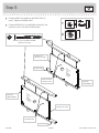
å
Fasten the ENDS (A2 and B2) to the FRONT LEGS (G
and H). Tihten six HIDDEN CAMS.
å
Fasten the REAR LEGS (I) to the ENDS (A2 and B2). Use
six BLACK 2-1/4" FLAT HEAD SCREWS (26S).
1
2
Surface
with
HIDDEN
CAMS
I
I
BLACK 2-1/4" FLAT HEAD SCREW
(6 used in this step)
26S
Surface
with
HIDDEN
CAMS
These surfaces
should be even.
The LEGS will
overhan this ede.
Ede with
CAM DOWELS
The LEGS will
overhan this ede.
Ede with
CAM DOWELS
Anled ede
Anled ede
These surfaces
should be even.
411201 www.sauder.com/servicesPae 10

Step 6
411201www.sauder.com/services
Pae 11
C2
A2
G
B2
H
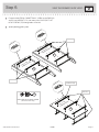
GOLD 5/16" FLAT HEAD SCREW
(24 used in this step)
3S
1
2
3
4
1
2
4
1
2
3
4
1
2
3
4
Glide end
Surface with
HIDDEN CAMS
Surface with
HIDDEN CAMS
1
2
4
Glide end
Finished ede
Surface with
HIDDEN CAMS
1
2
3
4
1
2
3
4
Glide end
1
2
3
4
3
4
3
4
3
3
å
Fasten the UNIVERSAL CABINET RAILS* (40DA) to the ENDS (A2
and B2) and UPRIGHT (C2). Use twenty-four GOLD 5/16" FLAT
HEAD SCREWS (3S) throuh holes #1 and #4.
å
*patent pendin lide system
VIEW THE DRAWER GLIDE VIDEO
1
2
3
4
1
2
4
3
3
3
3

Step 7
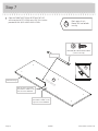
å
Open the FURNITURE TIPPING RESTRAINT KIT (97)
and fasten the SAFETY STRAP to the TOP (D2). Use the
provided BLACK 9/16" LARGE HEAD SCREW.
411201 www.sauder.com/servicesPae 12
D2
BLACK 9/16" LARGE HEAD SCREW
(1 used in this step)
Safety strap
97
Surface with holes
Unfi nished ede
Don't worry. It isn't
Rome. This can be built
in a day.
Use this hole if you prefer
the SAFETY STRAP on the
riht side of the UPRIGHT.
Use this hole if you prefer
the SAFETY STRAP on the
left side of the UPRIGHT.

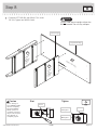
Step 8
å
Fasten the LEFT END (B2) and UPRIGHT (C2) to the
TOP (D2). Tihten four HIDDEN CAMS.
Start Tighten
Arrow
Minimum
190 derees
Caution
Risk of damae or
injury. HIDDEN CAMS
must be completely
tihtened. HIDDEN
CAMS that are not
completely tihtened
may loosen, and parts
may separate. To
completely tihten:
Arrow
Maximum
210 derees
B2
C2
D2
H
Finished ede
Lon fi nished ede
Surface
with
HIDDEN
CAMS
Do not stand the unit upriht without the
BACK fastened. The unit may collapse.
Caution
Surface
with
HIDDEN
CAMS
411201www.sauder.com/services
Pae 13
Surface with holes

Step 9
å
Insert four METAL PINS (1R) into the BOTTOMS (E2).
å
Fasten the BOTTOMS (E2) to the LEFT END (B2). Tihten
two HIDDEN CAMS.
å
NOTE: Be sure the METAL PINS in the BOTTOMS insert
into the holes in the LEFT END.
å
Fasten the BOTTOMS (E2) to the UPRIGHT (C2). Use two
BLACK 1-7/8" FLAT HEAD SCREWS (2S).
E2
E2
1R
Surface with
HIDDEN CAMS
Surface with
HIDDEN CAMS
Arrow
Minimum
190 derees
Maximum
210 derees
Finished ede
BLACK 1-7/8" FLAT HEAD SCREW
(2 used in this step)
2S
Finished ede
(4 used)
B2
C2
411201 www.sauder.com/servicesPae 14

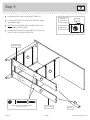
Step 10
å
Fasten the RIGHT END (A2) to the TOP (D2) and
BOTTOMS (E2). Tihten four HIDDEN CAMS.
å
NOTE: Be sure the METAL PINS in the BOTTOMS
insert into the holes in the RIGHT END.
Arrow
Minimum
190 derees
Maximum
210 derees
E2
E2
D2
A2
G
411201www.sauder.com/services
Pae 15

Step 11
å
Carefully turn your unit over onto its front edes. Unfold the BACK (F)
and lay it over your unit.
å
Push the SAFETY STRAP throuh the lare hole in the BACK (F).
å
First, make equal marins alon the top and bottom edes of the
BACK (F). Then, make equal marins alon the side edes of the BACK (F).
Push on opposite corners of your unit if needed to make it "square".
å
Fasten the BACK (F) to your unit usin the NAILS (1N).
å
NOTE: Be sure to tap NAILS into the holes that line up over
the UPRIGHT (C2).
NAIL
(47 used in this step)
1N
These holes must line up
over the UPRIGHT (C2).
F
Do not stand the unit upriht without the
BACK fastened. The unit may collapse.
Caution
411201 www.sauder.com/servicesPae 16
Before fastenin the BACK,
push the SAFETY STRAP
throuh one of these holes.

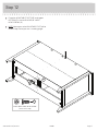
å
Fasten the ADJUSTABLE FOOT (34E) to the upper
BOTTOM (E2). Use four BLACK 9/16" LARGE
HEAD SCREWS (1S).
å
NOTE: Adjustments to the ADJUSTABLE FOOT will be
made in Step 13 once your unit is standin upriht.
Step 12
E2
34E
BLACK 9/16" LARGE HEAD SCREW
(4 used in this step)
1S
411201www.sauder.com/services
Pae 17

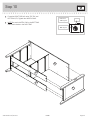
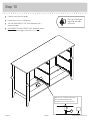
Step 13
å
Carefully stand your unit upriht.
å
Position your unit in its fi nal location.
å
Turn the ADJUSTABLE FOOT (34E) downward until it
touches the fl oor.
å
IMPORTANT: The ADJUSTABLE FOOT should not extend
beyond the bottom edes of the LEGS (G, H, and I).
With your No. 2 Phillips Screwdriver,
turn the ADJUSTABLE FOOT
downward until it touches the fl oor.
34E
Floor
Pro Tip: Lift with your
les. And, you know,
your arms.
G
H
I
34E
411201 www.sauder.com/servicesPae 18

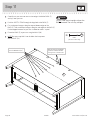
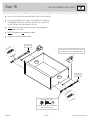
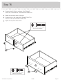
Step 14
å
Insert the DRAWER SIDES (D132 and D138) at
an angle into the slot at each end of the RIGHT
DRAWER FRONT (Q2).
å
Slide the DRAWER BOTTOM (D975) into the grooves in
the DRAWER SIDES (D132 and D138) and RIGHT
DRAWER FRONT (Q2).
å
Fasten the DRAWER BACK (D167) to the DRAWER
SIDES (D132 and D138) and DRAWER BRACE (M65). Use five
BLACK 1-9/16" FLAT HEAD SCREWS (30S). Repeat
this step for the other DRAWERS using the DRAWER
FRONTS (Q2 and R2). Use the SMALL DRAWER FRONTS (K2
and L2), SMALL DRAWER SIDES (D10 and D11), and SMALL
DRAWER BACKS (D166) for the small drawers.
The tabs should insert freely
into the slots. Gently tilt the
DRAWER SIDES side to side
until the tabs slip into the slots.
12
4
Be sure the DRAWER
BOTTOM inserts into the
DRAWER FRONT roove.
Groove
Q2
VIEW THE T-LOCK BOX VIDEO
D138
D975
D132
D132
D138
D167
Q2
D138
D132
M65
Start each screw a few turns before
completely tihtenin any of them.
BLACK 1-9/16" FLAT HEAD SCREW
(30 used in this step)
30S
With the palm of your hand,
tap the DRAWER BOTTOM
down into the roove.
Unfi nished
surface
411201www.sauder.com/services
Pae 19
Be sure the
DRAWER
BOTTOM
inserts into
the DRAWER
BACK roove.
å
Fasten the DRAWER BRACE (M65) to the
DRAWER FRONT (Q2). Tighten one HIDDEN CAM.
Surface with
HIDDEN CAM
3
Arrow
Maximum
210 derees
Minimum
190 derees
M65
Q2
Hidden part usin
recycled material.
Color may vary.

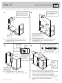
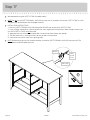
Step 15
å
Insert a SLIDE CAM (10A) into the DRAWER SIDES (D132 and D138).
å
Fasten the DRAWER RIGHT (40DC) and DRAWER LEFT (40DD) to
the DRAWER SIDES (D132 and D138). Use four GOLD 5/16" FLAT
HEAD SCREWS (3S) throuh holes #1 and #2.
å
NOTE: The screw head in the CAM must be visible throuh the
slotted hole in the SLIDE.
å
NOTE: The lides are not intended to rotate.
å
Repeat this step for the other drawers.
1
2
Screw head - turn CAM to line up holes in
the SLIDES with holes in DRAWER SIDES
10A
10A
1
2
D138
D132
GOLD 5/16" FLAT HEAD SCREW
(24 used in this step)
3S
(4 screws per drawer)
411201 www.sauder.com/servicesPae 20
VIEW THE DRAWER GLIDE VIDEO
Glide end
Glide end
La page est en cours de chargement...
La page est en cours de chargement...
La page est en cours de chargement...
La page est en cours de chargement...
La page est en cours de chargement...
La page est en cours de chargement...
La page est en cours de chargement...
La page est en cours de chargement...
La page est en cours de chargement...
La page est en cours de chargement...
La page est en cours de chargement...
La page est en cours de chargement...
La page est en cours de chargement...
La page est en cours de chargement...
La page est en cours de chargement...
La page est en cours de chargement...
-
 1
1
-
 2
2
-
 3
3
-
 4
4
-
 5
5
-
 6
6
-
 7
7
-
 8
8
-
 9
9
-
 10
10
-
 11
11
-
 12
12
-
 13
13
-
 14
14
-
 15
15
-
 16
16
-
 17
17
-
 18
18
-
 19
19
-
 20
20
-
 21
21
-
 22
22
-
 23
23
-
 24
24
-
 25
25
-
 26
26
-
 27
27
-
 28
28
-
 29
29
-
 30
30
-
 31
31
-
 32
32
-
 33
33
-
 34
34
-
 35
35
-
 36
36


dans d''autres langues
Documents connexes
-
Sauder 412301 Mode d'emploi
-
-
-
-
-
-
-
-
-

