S+S Regeltechnik RHEASGARD® KLGF-Modbus / KLGFVT-Modbus RHEASGARD® KLGF-Modbus / KLGFVT-Modbus Mode d'emploi
- Taper
- Mode d'emploi

D
G
F r
RHEASGARD® KLGF -Modbus
RHEASGARD® KLGFVT-Modbus
D
Bedienungs- und Montageanleitung
Kanal-Luftstromfühler bzw. Messumformer für
Strömungsgeschwindigkeit, Volumenstrom und Temperatur,
inkl. Montageflansch, kalibrierfähig, mit
Modbus
-Anschluss
G
Operating and Mounting Instructions
Duct air flow sensor or measuring transducer for
flow velocity, volume flow and temperature,
incl. mounting flange, calibratable,
Modbus
connector
F
Notice d’instruction
Capteur de débit d’air pour montage en gaine,
resp. convertisseur de mesure pour vitesse d’écoulement,
débit volumique et température,
avec bride de montage, étalonnable, avec raccordement
Modbus
r
Руководство по монтажу и обслуживанию
Канальный датчик воздушного потока или измерительный
преобразователь для измерения скорости потока, объемного
расхода и температуры, включ. присоединительный фланец,
калибруемый, подключение к шине
Modbus
CA RT ON S
ET EMBALLAGE
PAPIER À TRIER
KLGFVT - Modbus
KLGF - Modbus
KLGF - Modbus
KLGFVT - Modbus
S+S REGELTECHNIK GMBH
THURN-UND-TAXIS-STR. 22
90411 NÜRNBERG ⁄ GERMANY
FON +49
(0) 911 ⁄ 5 19 47- 0
mail@SplusS.de
www
.
SplusS.de
6000-4010-0000-1XX 40100 -2023 V101 04 ⁄ 2023

2
D
G
F r
RHEASGARD® KLGF -Modbus
RHEASGARD® KLGFVT-Modbus
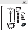
MFT - 20 - K
Montageflansch aus Kunststoff
Mounting flange, plastic
Bride de montage en matière plastique
Присоединительный фланец из пластика
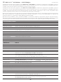
Maßzeichnung
Dimensional drawing
Plan coté
Габаритный чертеж
[mm]
Maßzeichnung
Dimensional drawing
Plan coté
Габаритный чертеж
[mm]
~ 200
126
112
90
50
ø 20
ø32.3
13.4
20
60
87
~30
32
62
M4
ø5.2
ø
20
M16x1.5
20
M16x1.5
112
4
~ 112

3
Kalibrierfähiger Kanal-Luftstromfühler
RHEASGARD
®
KLGF - Modbus
mit Modbus-Anschluss, Gehäuse aus schlagfestem Kunststoff mit Schnellver-
schlussschrauben, mit Kabelverschraubung (optional M12-Steckverbinder nach DIN EN 61076-2-101), wahlweise mit / ohne Display, zur Erfassung
der Strömungs geschwindigkeit (0,1...20 m/s).
Kalibrierfähiger Kanal-Luftstromfühler
RHEASGARD
®
KLGFVT - Modbus
mit Modbus-Anschluss, Gehäuse aus schlagfestem Kunststoff mit Schnell-
verschlussschrauben, mit Kabelverschraubung (optional M12-Steckverbinder nach DIN EN 61076-2-101), wahlweise mit / ohne Display, zur Erfassung
der Strömungs geschwindigkeit (0,1...20 m/s) und Temperatur (0...+50 °C). Über den Modbus können folgende Kenn größen abgefragt werden:
Strömungs geschwindigkeit, Volumenstrom (errechnet) und Temperatur.
Die Strömungsfühler sind geeignet zur Überwachung oder Steuerung von Luftströmungen in Kanälen, an Ventilatoren, Stell klappen, zum strömungs-
abhängigen Überwachen von Befeuchtern und elektrischen Heiz registern gemäß DIN 57100 Teil 420 oder zum Einsatz in Verbindung mit DDC-Anlagen.
Innovativer Modbusfühler mit galvanisch getrennter RS485-Modbus-Schnittstelle, zuschalt barem Busabschluss widerstand, DIP-Schalter zur Einstel-
lung der Busparameter und Busadresse im strom losen Zustand, interne LEDs zur Telegrammstatusanzeige, zwei getrennte Push-in-Klemmen und
großem dreizeiligem Display (beleuchtet). Der Fühler ist werkseitig kalibriert.
TECHNISCHE DATEN
Spannungsversorgung: 24 V AC ⁄ DC (± 10 %)
Stromaufnahme: ca. 4 VA
Datenpunkte: Strömungs geschwindigkeit [m/s], Volumenstrom [m³/h], Temperatur [°C]
LUFTSTROM
Sensor: kalorimetrisch, temperaturkompensiert, Fühlerbruchsicherung,
mit manueller Nullpunktkalibrierung (über Taster)
Messbereich: 0,1...20 m/s
Genauigkeit: 0,5 m/s + 3 % MW
Langzeitstabilität: ± 0,5 % EW pro Jahr
Reproduzierbarkeit: ± 1,0 % EW
Einlaufzeit: < 2 min
Ansprechzeit: < 60 s
Anlaufüberbrückung: 0...120 s (über Poti einstellbar)
TEMPERATUR
KLGF
(
V
)
T
Sensor: NTC 10k
Messbereich: 0...+50 °C
Genauigkeit: typisch ± 0,5 K bei +25 °C
Busprotokoll: Modbus (RTU-Mode), Adressbereich 0...
247
einstellbar
Signalfilterung: 0...30 Werte
Schutzrohr:
PLEUROFORM
TM, Werkstoff Polyamid (PA6), verdrehsicher, Ø 20 mm, NL = 220 mm, vmax = 30 m/s (Luft),
optional auf Anfrage
aus Edelstahl V2A
(1.4301)
,
Ø 16 mm
Gehäuse: Kunststoff,
UV-beständig,
Werkstoff Polyamid, 30 % glaskugelverstärkt,
mit Schnellverschlussschrauben(Schlitz ⁄ Kreuzschlitz-Kombination),
Farbe Verkehrsweiß (ähnlich RAL 9016), Deckel für Display ist transparent!
Abmaße Gehäuse: 126 x 90 x 50 mm (Tyr 2)
Kabelanschluss:
Kabelverschraubung
aus Kunststoff (M 16 x 1,5 ; mit Zugentlastung, auswechselbar,
max. Innendurchmesser 10,4 mm), optional mit
M12-Steckverbinder
nach DIN EN 61076-2-101
elektrischer Anschluss: 0,2 - 1,5 mm2, über Push-In-Klemme
Prozessanschluss: mittels Montageflansch (im Lieferumfang enthalten)
Umgebungstemperatur: Lagerung –20...+50 °C; Betrieb 0...+50 °C
Mediumstemperatur: 0...+70 °C
zulässige Luftfeuchte: < 98 % RH, nicht kondensierende, schadstofffreie Luft
Schutzklasse: III (nach EN 60 730)
Schutzart:
IP 65
(nach EN 60 529) Gehäuse; Sensorik IP 20
Normen: CE-Konformität nach EMV-Richtlinie 2014 ⁄ 30 ⁄ EU, nach EN 61326-1, nach EN 61326-2-3
Optional:
Display mit Beleuchtung,
dreizeilig, Ausschnitt ca. 70 x 40 mm (B x H),
zur Anzeige von Strömungs geschwindigkeit, Volumenstrom und Temperatur (zyklisch)
oder einer wählbaren Kenngröße (statisch)
D RHEASGARD® KLGF-Modbus ⁄ KLGFVT-Modbus
Rev. Data - V13

4
D RHEASGARD® KLGF-Modbus ⁄ KLGFVT-Modbus
Rev. Data - V13
ANLAUFÜBERBRÜCKUNG
Es gibt Anwendungsfälle, bei welchen Lüftermotoren und Messgeräte ab- und wieder zugeschaltet werden.
Beim Zuschalten benötigen die Lüfter einige Sekunden zum Aufbau einer Strömung.
Während dieser Anlaufzeit könnte die GLT auf Störung schalten (fehlende Strömung).
Beim
KLGF-Modbus sowie beim KLGFVT-Modbus
erfolgt die Aktivierung und Einstellung der Anlaufüberbrückung (0...120 s) über ein Potentiometer.
Nach Zuschalten der Versorgungsspannung wird während dieser Anlaufzeit eine Strömung von 20 m/s ausgegeben.
Nach Ablauf der Anlaufzeit wechselt das Gerät in den normalen Messmodus.
WEITERE KENNGRÖSSEN
Beim
KLGFVT-Modbus
wird über einen weiteren Sensor (NTC 10k) die Temperatur erfasst.
Zusätzlich wird die intern berechnete Kenngröße Volumenstrom bereitgestellt.
Dieser Wert kann im Display angezeigt werden. Die Umschaltung erfolgt per Register.
Typ ⁄ WG01 Messbereiche
Strömungs-
geschwindigkeit Volumenstrom Temperatur
Ausgang
Display
Art.-Nr.
KLGF-Modbus
KLGF-Modbus 0,1...20 m/s – – Modbus 1701-4216-0101-000
KLGF-Modbus
LCD
0,1...20 m/s – – Modbus ■1701-4216-1101-000
KLGFVT-Modbus
KLGFVT-Modbus 0,1...20 m/s 0...200.000 m³/h 0...+50 °C Modbus 1701-4216-0401-000
KLGFVT-Modbus
LCD
0,1...20 m/s 0...200.000 m³/h 0...+50 °C Modbus ■1701-4216-1401-000
Optional: Kabelanschluss mit
M12-Steckverbinder
nach DIN EN 61076-2-101 auf Anfrage
ZUBEHÖR
KA2 -
Modbus Kommunikationsadapter
(USB/RS485) zur Systemanbindung 1906-1200-0000-100
LA -
Modbus Leitungsabschlussgerät
(mit Abschlusswiderstand) als aktiver Busabschluss 1906-1300-0000-100
MFT-20-K
Montageflansch
aus Kunststoff (im Lieferumfang enthalten) 7000-0031-0000-000

5
D RHEASGARD® KLGF-Modbus ⁄ KLGFVT-Modbus
Rev. Data - V13
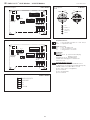
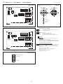
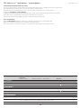
Schaltbild
Schaltbild
Anschlussbild
Stecker belegung
(M12)
KLGF - Modbus
KLGFVT - Modbus
KLGF - Modbus
KLGFVT - Modbus
xx - Modbus
zero
set
ok
err.
up
down
address
sb
12345678
ON DIP A
mode
123456
ON DIP B
21 3 4 5
2
1 3 4 5
shield
U+
GND
A
B
Stecker
Display
LEDs
zero
set
ok
err.
up
down
address
offsetsb
12345678
ON DIP A
mode
123456
ON DIP B
21 3 4 5
21 3 4 5
shield
U+
GND
A
B
Stecker
Display
LEDs
5
1
2
3
4
+UB 24V AC/DC
–UB GND
A
B
Shield
1
2
3
4
5
45°
1
2
3
4
5
45°
1 3
2
4
5
MALE FEMALE
+UB
Modbus A
–UB GND
Modbus B
Shield
zero
set
ok
err.
up
down
address
offsetsb
12345678
ON DIP A
mode
123456
ON DIP B
21 3 4 5
21 3 4 5
shield
U+
GND
A
B
Stecker
Display
LEDs
SET-Potentiometer
sb
= Anlaufüberbrückung (min. 0s ... max. 120s)
offset
= Temperatur (± 5K)
LEDs
(on = aktiv)
sb
= Anlaufüberbrückung
ok
= fehlerfreies Protokoll empfangen
err.
= fehlerhaftes Protokoll oder Checksumme
Taster
zero ⁄ set:
2 s gedrückt halten → Aktivierung des Menüs
auf dem Display (Display-Varianten)
10 s gedrückt halten → Nullpunkt setzen (0m/s)
(LED-sb blinkt während des Vorgangs und erlischt,
wenn Nullpunkt gesetzt ist)
up ⁄ down (Display-Varianten):
Bei aktivem Menü (2 s zero ⁄ set-Taste), Wechsel
zwischen "Flow" (Strömungsgeschwindigkeit) und
Vol (Volumenstrom), Bestätigung mit zero ⁄ set-Taste.
Bei Auswahl "Vol"
→ Eingabe Fläche in cm² (up ⁄ down)
→ zero ⁄ set-Taste
→ Eingabe der Einheit (up ⁄ down)
→ zero ⁄ set-Taste

6
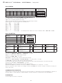
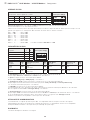
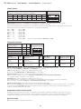
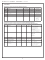
BUSADRESSE
Busadresse
(binärcodiert, Wertigkeit 1 bis 247 einstellbar)
MODBUS
DIP-Schalter [A]
DIP 1 DIP 2 DIP 3 DIP 4 DIP 5 DIP 6 DIP 7 DIP 8
1 2 3 4 5 6 7 8
ON DIP A
128 64 32 16 8421
O N O N
OFF OFF OFF OFF OFF
O N
Beispiel zeigt 128 + 64 + 1 = 193 als Modbus-Adresse.
Die
Geräteadresse
im Bereich von
1 bis 247
(Binärformat) wird über den DIP-Schalter [A] eingestellt.
Schalterstellung Pos. 1 bis 8 – siehe Tabelle auf Rückseite!
Die Adresse 0 ist für Broadcast-Meldungen reserviert, die Adressen größer 247 dürfen nicht belegt werden
und werden vom Gerät ignoriert. Die DIP-Schalter sind binärcodiert mit folgender Wertigkeit:
DIP 1 =
128
............ DIP 1 =
ON
DIP 2 =
64
............ DIP 2 =
ON
DIP 3 = 32 ............ DIP 3 = OFF
DIP 4 = 16 ............ DIP 4 = OFF
DIP 5 = 8 ............ DIP 5 = OFF
DIP 6 = 4 ............ DIP 6 = OFF
DIP 7 = 2 ............ DIP 7 = OFF
DIP 8 =
1
............ DIP 8 =
ON
folgt die Modbus-Adresse
128 + 64 + 1 = 193
BUSPARAMETER
Baudrate
(einstellbar)
DIP
1
DIP
2
MODBUS
DIP-Schalter [B]
9600 Baud
O N
OFF
1 2 3 4 5 6
ON DIP B
19200 Baud
O N O N
38400 Baud OFF
O N
reserviert OFF OFF
Parity
(einstellbar)
DIP
3
Parity-Sicherung
(ein/aus)
DIP
4
8N1-Modus
(ein/aus)
DIP
5
Busabschluss
(ein/aus)
DIP
6
EVEN
(gerade)
O N
aktiv
(1 Stoppbit)
O N
aktiv
O N
aktiv
O N
ODD
(ungerade) OFF inaktiv (keine Parität)
(2 Stoppbits) OFF inaktiv
(Default) OFF inaktiv OFF
Die
Baudrate
(Übertragungsgeschwindigkeit) wird über Pos. 1 und 2 des DIP-Schalters [B] eingestellt.
Einstellbar sind
9600 Baud
,
19200 Baud
oder
38400 Baud
– siehe Tabelle !
Die
Parity
wird über Pos. 3 des DIP-Schalters [B] eingestellt.
Einstellbar sind
EVEN (gerade)
oder
ODD (ungerade)
– siehe Tabelle !
Die
Parity-Sicherung
wird über Pos. 4 des DIP-Schalters [B] aktiviert.
Einstellbar ist Parity-Sicherung
aktiv (1 Stoppbit)
oder
inaktiv (2 Stoppbits)
, d.h. keine Parity-Sicherung – siehe Tabelle !
Der 8N1-Modus wird über Pos. 5 des DIP-Schalters [B] aktiviert.
Die Funktionalität der Pos. 3 (Parity) und Pos. 4 (Parity-Sicherung) des DIP-Schalters [B] wird somit deaktivert.
Einstellbar ist 8N1 aktiv oder inaktiv (Default) – siehe Tabelle !
Der
Busabschluss
wird über Pos. 6 des DIP-Schalters [B] aktiviert.
Einstellbar ist
aktiv
(Busabschlusswiderstand von 120 Ohm) oder
inaktiv
(ohne Busabschluss) – siehe Tabelle !
Bei Änderung der Busparameter und Busadresse werden bei Geräten mit
Displayanzeige
die entsprechenden Einstellungen
im Display für ca. 30 Sekunden angezeigt.
KOMMUNIKATIONSANZEIGE
Die Kommunikation wird über 2 LED-Anzeigen signalisiert. Fehlerfrei empfangene Telgramme werden unabhängig von
der Geräteadresse durch Aufleuchten der grünen Anzeige signalisiert. Fehlerhafte Telegramme oder ausgelöste Modbus
Exception-Telegramme werden durch das Aufleuchten der roten Anzeige dargestellt.
DIAGNOSE
Fehlerdiagnosefunktion integriert
D RHEASGARD® KLGF-Modbus ⁄ KLGFVT-Modbus
| Konfiguration

7
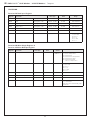
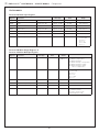
TELEGRAMME
Function 04 Read Input Register
Register Parameter Data Type Value Range
0003 Flow Abtastung 4 s Signed 16 Bit 0...200 0.0...20.0 m⁄s
0004 Flow Filterung max. 32 s Signed 16 Bit 0...200 0.0...20.0 m⁄s
0006 Temperatur Abtastung 4 s Signed 16 Bit 0...500 0.0...50.0 °C
0007 Temperatur Filterung max. 32 s Signed 16 Bit 0...500 0.0...50.0 °C
0008 Volumenstrom Abtastung 4 s Signed 16 Bit 0...30000 0...30000
0009 Volumenstrom Filterung max. 32 s Signed 16 Bit 0...30000 0...30000
0010 Volumenstrom Einheit Signed 16 Bit 0...5 0 = m³ ⁄ h
1 = m³ ⁄ min
2 = m³ ⁄ s
3 = l ⁄ h
4 = l ⁄ min
5 = l ⁄ s
Function 06 Write Single Register &
Function 16 Write Multiple Register
Register Parameter Data Type Value default
0001 Displaydarstellung Signed 16 Bit 0...5 KLGF 0
KLGFVT 5
0 = Strömung
1 = Strömung + Temperatur
2 = Volumenstrom
3 = Volumenstrom + Temperatur
4 = Volumenstrom + Strömung
5 = Volumenstrom / Strömung
altern. + Temperatur
0002 Einheit Volumenstrom Signed 16 Bit 0...5 0 0 = m³ ⁄ h
1 = m³ ⁄ min
2 = m³ ⁄ s
3 = l ⁄ h
4 = l ⁄ min
5 = l ⁄ s
0004 digitaler Offset Strömung Signed 16 Bit –50...50 0 –5.0...5.0 m ⁄ s
0007 digitaler Offset Temperatur Signed 16 Bit –50...50 0 –5.0...5.0 °C
0009 Kanalquerschnitt in cm² Signed 16 Bit 10...30000 10000 10 cm²...30000 cm²
0015 Nullpunkt setzen (0 m/s) Signed 16 Bit 0...1 0 0 = inaktiv
1 = setzen / aktivieren
(anschießend springt der Wert
automatisch wieder auf 0)
D RHEASGARD® KLGF-Modbus ⁄ KLGFVT-Modbus
| Telegramme

8
D
Modbus
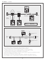
| Installation
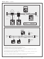
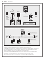
Allgemeiner Aufbau Busstruktur
Bustopologie mit Abschluss- und Vorspannungswiderständen
Abschlusswiderstände dürfen nur an den Enden der Busleitung angebracht werden.
In Netzen ohne Repeater sind nicht mehr als 2 Leitungsabschlüsse erlaubt.
Über DIP 6 kann der Leitungsabschluss am Gerät aktiviert werden. Die Vorspannungswiderstände zur Buspegeldefinition
im Ruhezustand werden üblicherweise am Modbus-Master / Repeater aktiviert.
Die maximale Teilnehmerzahl pro Modbussegment beträgt 32 Geräte.
Bei größerer Teilnehmerzahl ist der Bus in mehrere über Repeater getrennte Segmente aufzuteilen.
Die Teilnehmeradresse kann von 1 bis 247 eingestellt werden.
Für die Busleitung ist ein Kabel mit paarverseilter Datenleitung / Spannungsversorgung und Kupferabschirmgeflecht zu verwenden.
Der Kapazitätsbelag der Leitung sollte dabei kleiner 100 pF/m betragen (z.B. Profibusleitung).
Slave n
MODBUS
RTU-Master
RS-485
Leitungs-
abschluss
Leitungs-
abschluss
Aktiver
Abzweig
Passiver
Abzweig
Stichleitung
(Drop-Kabel)
Stammleitung
(Trunk-Kabel)
Stichleitung:
kürzer 20m
Mehrfachabzweigung n:
kürzer 40m/n
Allgemeiner Aufbau Busstruktur
Slave 1 Slave 2
LA LA
Bustopologie mit Abschluss- und Vorspannungswiderständen
A (D1) D+
5 V
Common
(GND)
B (D0) D–
Leitungs-
abschluss
Pull-Down- /
Vorspannungswiderstand
Pull-Up- /
Vorspannungswiderstand
MODBUS
RTU-Master
Slave 1 Slave 2
RBIAS
RBIAS
RAB
Leitungs-
abschluss
RAB

9
D
Wichtige Hinweise
– Dieses Gerät darf nur in schadstofffreier, nicht kondensierender Luft, ohne Über- oder Unterdruck am Sensorelement eingesetzt werden.
– Staub- und Verunreinigungen verfälschen das Messergebnis und sind zu vermeiden.
Geringe Verunreinigungen und Staubablagerungen können mit Druckluft beseitigt werden.
– Bei Verunreinigungen empfehlen wir eine werksseitige Reinigung und Neukalibrieung.
– Chemikalien oder andere Reinigungsmittel dürfen unter keinen Umständen auf den Sensor gelangen.
– Der chemische Sensor ist Verbrauchsmaterial. Die Lebensdauer des Sensors hängt von Art und Konzentration der Schadgasbelastung ab.
– Beim Anschluss mehrerer Fühler an eine gemeinsame Spannungsversorgung mit 24 V AC (Wechselspannung) ist auf die Polung zu achten,
da sonst die Wechselspannungsquelle kurz geschlossen werden kann.
– Die Ausgänge sind kurzschlussfest, ein Anlegen einer Überspannung oder der Spannungsversorgung am Ausgang zerstört das Gerät.
– Beim Betrieb des Gerätes ausserhalb des Spezifikationsbereiches entfallen alle Garantieansprüche.
Als AGB gelten ausschließlich unsere sowie die gültigen „Allgemeinen Lieferbedingungen für Erzeugnisse und Leistungen der Elektro industrie“
(ZVEI Bedingungen) zuzüglich der Ergänzungsklausel „Erweiterter Eigentumsvorbehalt“.
Außerdem sind folgende Punkte zu beachten:
– Vor der Installation und Inbetriebnahme ist diese Anleitung zu lesen und die alle darin gemachten Hinweise sind zu beachten!
– Der Anschluss der Geräte darf nur an Sicherheitskleinspannung und im spannungslosen Zustand erfolgen. Um Schäden und Fehler am Gerät
(z.B. durch Spannungsinduktion) zu verhindern, sind abgeschirmte Leitungen zu verwenden, eine Parallelverlegung zu stromführenden Leitungen
zu vermeiden und die EMV- Richtlinien zu beachten.
– Dieses Gerät ist nur für den angegebenen Verwendungszweck zu nutzen, dabei sind die entsprechenden Sicherheitsvorschriften des VDE,
der Länder, ihrer Überwachungsorgane, des TÜV und der örtlichen EVU zu beachten.
Der Käufer hat die Einhaltung der Bau- und Sicherungsbestimmung zu gewährleisten und Gefährdungen aller Art zu vermeiden.
– Für Mängel und Schäden, die durch unsachgemäße Verwendung dieses Gerätes entstehen,
werden keinerlei Gewährleistungen und Haftungen übernommen.
– Folgeschäden, welche durch Fehler an diesem Gerät entstehen, sind von der Gewährleistung und Haftung ausgeschlossen.
– Montage und Inbetriebnahme der Geräte darf nur durch Fachpersonal erfolgen.
– Es gelten ausschließlich die technischen Daten und Anschlussbedingungen der zum Gerät gelieferten Montage- und Bedienungs anleitung,
Abweichungen zur Katalogdarstellung sind nicht zusätzlich aufgeführt und im Sinne des technischen Fortschritts und der stetigen Verbesserung
unserer Produkte möglich.
– Bei Veränderungen der Geräte durch den Anwender entfallen alle Gewährleistungsansprüche.
– Dieses Gerät darf nicht in der Nähe von Wärmequellen (z.B. Heizkörpern) oder deren Wärmestrom eingesetzt werden,
eine direkte Sonnen einstrahlung oder Wärmeeinstrahlung durch ähnliche Quellen (starke Leuchte, Halogenstrahler) ist unbedingt zu vermeiden.
– Der Betrieb in der Nähe von Geräten, welche nicht den EMV- Richtlinien entsprechen, kann zur Beeinflussung der Funktionsweise führen.
– Dieses Gerät darf nicht für Überwachungszwecke, welche dem Schutz von Personen gegen Gefährdung oder Verletzung dienen und
nicht als Not-Aus-Schalter an Anlagen und Maschinen oder vergleichbare sicherheitsrelevante Aufgaben verwendet werden.
– Die Gehäuse- und Gehäusezubehörmaße können geringe Toleranzen zu den Angaben dieser Anleitung aufweisen.
– Veränderungen dieser Unterlagen sind nicht gestattet.
– Reklamationen werden nur vollständig in Originalverpackung angenommen.
Hinweise zur Inbetriebnahme:
Dieses Gerät wurde unter genormten Bedingungen kalibriert, abgeglichen und geprüft. Bei Betrieb unter abweichenden Bedingungen empfehlen wir Vorort
eine manuelle Justage erstmals bei Inbetriebnahme sowie anschließend in regelmäßigen Abständen vorzunehmen.
Eine Inbetriebnahme ist zwingend durchzuführen und darf nur von Fachpersonal vorgenommen werden!
Vor der Montage und Inbetriebnahme ist diese Anleitung zu lesen und die alle darin gemachten Hinweise sind zu beachten!
Hinweise zur Montage:
Der Einbau hat unter Berücksichtigung der einschlägigen, für den Mess ort gültigen Vorschriften und Standards (wie z. B. Schweiß vor schriften usw.) zu
erfolgen. Insbesondere sind zu berücksichtigen:
– VDE ⁄ VDI Technische Temperaturmessungen, Richtlinie, Mess an ordnungen für Temperaturmessungen
– die EMV-Richtlinien, diese sind einzuhalten
– eine Parallelverlegung mit stromführenden Leitungen ist unbedingt zu vermeiden
– es wird empfohlen abgeschirmte Leitungen zu verwenden, dabei ist der Schirm einseitig an der DDC ⁄ SPS aufzulegen.
Der Einbau hat unter Beachtung der Übereinstimmung der vor liegenden technischen Parameter des Messgeräts mit den realen Einsatzbedingungen zu
erfolgen, insbesondere:
– Messbereich
– zulässiger maximaler Druck, Strömungsgeschwindigkeit, Temperatur und Feuchte
– Schutzart und Schutzklasse
– Einbaulänge, Rohrmaße
– Schwingungen, Vibrationen, Stöße sind zu vermeiden (< 0,5 g)
Achtung! Berücksichtigen Sie in jedem Fall die mechanischen und thermischen Belastungsgrenzen der Schutzrohre nach DIN 43763 bzw. nach
speziellen S+S-Standards!

10
G
RHEASGARD® KLGF-Modbus ⁄ KLGFVT-Modbus
Rev. Data - V13
Calibratable duct air flow sensor
RHEASGARD
®
KLGF - Modbus
with Modbus connector, housing made of impact-resistant plastic with quick-locking
screws, with cable gland (optional M12-connector as per DIN EN 61076-2-101) optionally with / without display, to determine the flow velocity
(0.1...20 m/s).
Calibratable duct air flow sensor
RHEASGARD
®
KLGFVT - Modbus
with Modbus connector, housing made of impact-resistant plastic with quick-
locking screws, with cable gland (optional M12-connector as per DIN EN 61076-2-101) optionally with/without display, to determine the flow velocity
(0.1...20 m/s) and temperature (0...+50 °C). The following parameters can be retrieved from the Modbus: flow velocity, volume flow (calculated) and
temperature.
The flow sensors are suitable for monitoring or controlling airflows in ducts, at fans and dampers, for flow-dependent monitoring of humidifiers and
electric heating registers according to DIN 57100, Sect. 420, or for use in connection with DDC systems.
Innovative Modbus sensor with galvanically separated RS485 Modbus interface, selectable bus termination resistance, DIP switch for setting the
bus parameters and bus address in current-free state, internal LEDs for telegram status display, two separate push-in terminals and large three-line
display (illuminated). The sensor is factory-calibrated.
TECHNICAL DATA
Power supply: 24 V AC ⁄ DC (± 10%)
Current consumption: approx. 4 VA
Data points: Flow velocity [m/s], volume flow [m³/h], temperature [°C]
AIR FLOW
Sensor: Calorimetric, temperature compensated, sensor breakage protection,
with manual zero-point calibration (via button)
Measuring range: 0.1...20 m/s
Accuracy: 0.5 m/s + 3% measured value
Long-term stability: ± 0.5% final value per year
Reproducibility: ± 1.0% final value
Warm-up time: < 2 min
Response time: < 60 s
Start-up override: 0...120 s (adjustable via potentiometer)
TEMPERATURE
KLGF
(
V
)
T
Sensor: NTC 10k
Measuring range: 0...+50 °C
Accuracy: typical ± 0.5 K at +25 °C
Bus protocol: Modbus (RTU mode), address range 0...
247
selectable
Signal filtering: 0...30 values
Protective tube:
PLEUROFORM
TM, material polyamide (PA6), with torsion protection, Ø 20mm, NL = 220 mm, vmax = 30 m/s (air),
stainless steel V2A
(1.4301)
,
Ø 16 mm available upon request as an option
Housing: Plastic,
UV-resistant,
polyamide material, 30% glass-globe reinforced,
with quick-locking screws(slotted ⁄ Phillips head combination),
colour traffic white (similar to RAL 9016), housing cover for display is transparent!
Housing dimensions: 126 x 90 x 50 mm (Tyr 2)
Cable connection:
Cable gland
made of plastic (M16 x 1.5; with strain relief, replaceable,
max. inner diameter 10.4 mm),
optionally with
M12 connector
as per DIN EN 61076-2-101
Electrical connection: 0.2 - 1.5 mm2, via push-in terminal
Process connection: by means of plastic mounting flange (included in the scope of delivery)
Ambient temperature: Storage –20...+50 °C; operation 0...+50 °C
Medium temperature: 0...+70 °C
Permitted humidity: < 98% RH, non-precipitating air free of harmful substances
Protection class: III (according to EN 60 730)
Protection type:
IP 65
(according to EN 60 529) housing; IP 20 sensor technology
Standards: CE conformity according to EMC Directive 2014 ⁄ 30 ⁄ EU, according to EN 61326-1, according to EN 61326-2-3
Optional:
Display with illumination,
three-line, cutout approx. 70 x 40 mm (W x H),
to display the flow velocity, volume flow and temperature (cyclical)
or a selectable parameter (static)

11
G
RHEASGARD® KLGF-Modbus ⁄ KLGFVT-Modbus
Rev. Data - V13
START-UP SUPPRESSION
There are application scenarios in which fan motors and measuring instruments are switched off and on again.
When switched on, the fans take a few seconds to build up a flow.
During this start-up time, the BMS could switch to fault mode (lack of flow).
The start-up override (0…120s) for the
KLGF Modbus and the KLGFVT Modbus
is activated and set via a potentiometer.
After switching on the supply voltage, a flow of 20m/s is delivered during this start-up time.
After the start-up time has elapsed, the unit switches to normal measuring mode.
OTHER PARAMETERS
In the
KLGFVT Modbus
, the temperature is captured by another sensor (NTC 10k).
The internally calculated volume flow parameter is also provided.
This value can be shown in the display. Switching is done by register.
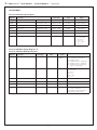
Type ⁄ WG01 Measuring
ranges
Flow velocity Volume flow Temperature
Output
Display
Item no.
KLGF-Modbus
KLGF-Modbus 0,1...20 m/s – – Modbus 1701-4216-0101-000
KLGF-Modbus
LCD
0,1...20 m/s – – Modbus ■1701-4216-1101-000
KLGFVT-Modbus
KLGFVT-Modbus 0,1...20 m/s 0...200.000 m³/h 0...+50 °C Modbus 1701-4216-0401-000
KLGFVT-Modbus
LCD
0,1...20 m/s 0...200.000 m³/h 0...+50 °C Modbus ■1701-4216-1401-000
Optional: Cable connection with
M12 connector
as per DIN EN 61076-2-101 on request
ACCESSORIES
KA2 -
Modbus Communication adapter
(USB/RS485) for system connection 1906-1200-0000-100
LA -
Modbus Line termination device
(with terminating resistor) as an active bus termination
1906-1300-0000-100
MFT-20-K
Mounting flange
, plastic (included in the scope of delivery) 7000-0031-0000-000

12
G
RHEASGARD® KLGF-Modbus ⁄ KLGFVT-Modbus
Rev. Data - V13
Schematic diagram
Schematic diagram
Connecting diagram
Pin assignment
(M12)
KLGF - Modbus
KLGFVT - Modbus
KLGF - Modbus
KLGFVT - Modbus
xx - Modbus
zero
set
ok
err.
up
down
address
sb
12345678
ON DIP A
mode
123456
ON DIP B
21 3 4 5
2
1 3 4 5
shield
U+
GND
A
B
Plug for
display
LEDs
zero
set
ok
err.
up
down
address
offsetsb
12345678
ON DIP A
mode
123456
ON DIP B
21 3 4 5
21 3 4 5
shield
U+
GND
A
B
Plug for
display
LEDs
5
1
2
3
4
+UB 24V AC/DC
–UB GND
A
B
Shield
1
2
3
4
5
45°
1
2
3
4
5
45°
1 3
2
4
5
MALE FEMALE
+UB
Modbus A
–UB GND
Modbus B
Shield
zero
set
ok
err.
up
down
address
offsetsb
12345678
ON DIP A
mode
123456
ON DIP B
21 3 4 5
21 3 4 5
shield
U+
GND
A
B
Plug for
display
LEDs
SET potentiometer
sb
= start-up suppression (min. 0 s ... max. 120s)
offset
= temperature (± 5K)
LEDs
(on = active)
sb
= start- up suppression
ok
= error-free protocol received
err.
= faulty protocol or checksum
Pushbutton
zero ⁄ set:
Hold down for 2 s → activate menu on display
(display versions)
Hold down for 10 s → set zero (0m ⁄ s)
(sb LED flashes during process and turns off
when zero is set)
up ⁄ down (display
versions
):
When the menu is activated (2 s hold down of zero ⁄
set button), you can change between ‘Flow’ (flow speed)
and ‘Vol’ (volume rate). When ‘Vol’ is selected
→ enter surface area in cm² (up/down)
→ zero ⁄ set button
→ enter unit (up ⁄ down)
→ zero ⁄ set button

13
G
RHEASGARD® KLGF-Modbus ⁄ KLGFVT-Modbus
| Configuration
BUS ADDRESS
Bus address
(binary coded, value selectable from 1 to 247)
MODBUS
DIP switch [A]
DIP 1 DIP 2 DIP 3 DIP 4 DIP 5 DIP 6 DIP 7 DIP 8
128 64 32 16 8421
O N O N
OFF OFF OFF OFF OFF
O N
Example shows 128 + 64 + 1 = 193 as Modbus address.
The device address in the range of
1 to 247
is set at DIP switch [A].
For switch positions 1 to 8 see the table on the back!
Address 0 is reserved for broadcast messages.
Addresses greater than 247 must not be assigned and are ignored by the device.
The DIP switches are binary-coded with the following values:
DIP 1 =
128
............ DIP 1 =
ON
DIP 2 =
64
............ DIP 2 =
ON
DIP 3 = 32 ............ DIP 3 = OFF
DIP 4 = 16 ............ DIP 4 = OFF
DIP 5 = 8 ............ DIP 5 = OFF
DIP 6 = 4 ............ DIP 6 = OFF
DIP 7 = 2 ............ DIP 7 = OFF
DIP 8 =
1
............ DIP 8 =
ON
The switch positions shown here result in the Modbus address
128 + 64 + 1 = 193
BUS PARAMETER
S
Baud rate
(selectable)
DIP
1
DIP
2
MODBUS
DIP switch [B]
9600 baud
O N
OFF
19200 baud
O N O N
38400 baud OFF
O N
Reserved OFF OFF
Parity
(selectable)
DIP
3
Parity check
(on / off)
DIP
4
8N1 mode
(on / off)
DIP
5
Bus termination
(on/off)
DIP
6
EVEN
(numbered)
O N
Active
(1 stop bit)
O N
Active
O N
Active
O N
ODD
(numbered)OFF Inactive (no parity)
(2 stop bits) OFF Inactive (default) OFF Inactive OFF
The baud rate (speed of transmission) is set at DIP switches 1 and 2 of DIP switch block [B].
Selectable are
9600 baud, 19200 baud
,
or
38400 baud
– see table!
Parity
is set at DIP switch 3 of DIP switch block [B].
Selectable are
EVEN
or
ODD
– see table!
Parity check
is activated via DIP switch 4 of DIP switch block [B].
Selectable are
active (1 stop bit)
, or i
nactive (2 stop bits)
, i.e. no parity check – see table!
The
8N1 mode
is activated via DIP switch 5 of DIP switch block [B].
The functionality of DIP switch 3 (parity) and DIP switch 4 (parity check) of DIP switch block [B] is therefore deactivated.
Selectable are 8N1
active
or
inactive (default)
– see table !.
Bus termination
is activated via DIP switch 6 of DIP switch block [B].
Selectable are
active
(bus termination resistance of 120 Ohm), or
inactive
(no bus termination) – see table!
When bus parameters and bus address are changed at devices with
display
, the respective settings are shown on the display for
approx. 30 seconds.
COMMUNICATION INDICATOR
Communication is indicated via two LEDs. Error-free received telegrams are signalized by the green LED lighting up, regardless of
the device address. Faulty telegrams or triggered Modbus exception telegrams are depicted by the red LED lighting up.
DIAGNOSTICS
An error diagnostic function is integrated

14
G
RHEASGARD® KLGF-Modbus ⁄ KLGFVT-Modbus
| Telegrams
TELEGRAMS
Function 04 Read Input Register
Register Parameter Data Type Value Range
0003 Flow Sampling 4s Signed 16 Bit 0...200 0.0...20.0 m ⁄s
0004 Flow Filtering max. 32s Signed 16 Bit 0...200 0.0...20.0 m⁄s
0006 Temperature Sampling 4s Signed 16 Bit 0...500 0.0...50.0 °C
0007 Temperature Filtering max. 32s Signed 16 Bit 0...500 0.0...50.0 °C
0008 Volume flow Sampling 4s Signed 16 Bit 0...30000 0...30000
0009 Volume flow Filtering max. 32s Signed 16 Bit 0...30000 0...30000
0010 Volume flow Unit Signed 16 Bit 0...5 0 = m³ ⁄ h
1 = m³ ⁄ min
2 = m³ ⁄ s
3 = l ⁄ h
4 = l ⁄ min
5 = l ⁄ s
Function 06 Write Single Register &
Function 16 Write Multiple Register
Register Parameter Data Type Value default
0001 Display screen Signed 16 Bit 0...5 KLGF 0
KLGFVT 5
0 = flow
1 = flow + temperature
2 = volume flow
3 = volume flow + temperature
4 = volume flow + flow
5 = volume flow / flow
altern. + temperature
0002 Unit of volume flow Signed 16 Bit 0...5 0 0 = m³ ⁄ h
1 = m³ ⁄ min
2 = m³ ⁄ s
3 = l ⁄ h
4 = l ⁄ min
5 = l ⁄ s
0004 Flow digital offset Signed 16 Bit –50...50 0 –5.0...5.0 m ⁄ s
0007 Temperature digital offset Signed 16 Bit –50...50 0 –5.0...5.0 °C
0009 Channel cross-section in cm² Signed 16 Bit 10...30000 10000 10 cm²...30000 cm²
0015 Set zero point (0m/s) Signed 16 Bit 0...1 0 0 = inactive
1 = set/activate
(the value then automatically skips
back to 0)

15
G U
Modbus
| Installation
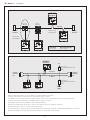
General layout of bus structure
Bus topology with terminating and bias resistors
Terminating resistor may only be installed at the ends of the bus line.
In networks with repeaters not more than two line terminations are allowed.
Line termination at the device can be activated via DIP switch 6.
The bias resistors for bus level definition in the resting state are usually activated at the Modbus master / repeater.
The maximum number of subscribers per Modbus segment is 32 devices.
When the number of subscribers is greater, the bus must be subdivided into several segments separated by repeaters.
The subscriber address can be set from 1 to 247.
For the bus line, a twisted-pair cable data line / power supply line and copper mesh wire shield must be used.
Therefore, the line capacitance should be less than 100 pF / m (e.g. Profibus cable).
Slave n
MODBUS
RTU-Master
RS-485
Line
termination
Line
termination
Active
branch
Passive
branch
Stub line
Trunk line
Stub line:
shorter 20m
Multiple branch n:
shorter 40m/n
General layout of bus structure
Slave 1 Slave 2
LA LA
Bus topology with terminating and bias resistors
A (D1) D+
B (D0) D–
MODBUS
RTU-Master
Slave 1 Slave 2
5 V
Common
(GND)
Line
termination
Pull-down /
bias resistor
Pull-up /
bias resistor
RBIAS
RBIAS
RAB
Line
termination
RAB

16
G U
Important notes
– This device may only be used in pollutant-free non-precipitating air without above-atmospheric or below-atmospheric pressure at the sensor element.
– Dust and pollution falsify measurement results and are to be avoided.
Slight pollution and dust sediments can be removed by using compressed air.
– In case of pollution, we recommend cleaning and recalibration in the factory.
– In any case, the sensor must not get in contact with chemicals or other cleaning agents.
– The chemical sensor is a consumable. The lifetime of the sensor depends on nature and concentration of the pollutant gas burden.
– When several sensors are connected to one voltage supply of 24 V AC, correct polarity must be regarded
as otherwise the alternating voltage source may be short-circuited.
– The outputs are short-circuit proof. Applying overvoltage or voltage supply to the output will destroy the device.
– If this device is operated beyond the specified range, all warranty claims are forfeited.
Our “General Terms and Conditions for Business“ together with the “General Conditions for the Supply of Products and Services of the Electrical and
Electronics Industry“ (ZVEI conditions) including supplementary clause “Extended Retention of Title“ apply as the exclusive terms and conditions.
In additionIn addition, the following points are to be observed:
– These instructions must be read before installation and putting in operation and all notes provided therein are to be regarded!
– Devices must only be connected to safety extra-low voltage and under dead-voltage condition. To avoid damages and errors the device (e.g. by voltage
induction) shielded cables are to be used, laying parallel with current-carrying lines is to be avoided, and EMC directives are to be observed.
– This device shall only be used for its intended purpose. Respective safety regulations issued by the VDE, the states, their control authorities,
the TÜV and the local energy supply company must be observed. The purchaser has to adhere to the building and safety regulations and has to prevent
perils of any kind.
– No warranties or liabilities will be assumed for defects and damages arising from improper use of this device.
– Consequential damages caused by a fault in this device are excluded from warranty or liability.
– These devices must be installed and commissioned by authorised specialists.
– The technical data and connecting conditions of the mounting and operating instructions delivered together with the device are exclusively valid.
Deviations from the catalogue representation are not explicitly mentioned and are possible in terms of technical progress and continuous
improvement of our products.
– In case of any modifications made by the user, all warranty claims are forfeited.
– This device must not be installed close to heat sources (e.g. radiators) or be exposed to their heat flow.
Direct sun irradiation or heat irradiation by similar sources (powerful lamps, halogen spotlights) must absolutely be avoided.
– Operating this device close to other devices that do not comply with EMC directives may influence functionality.
– This device must not be used for monitoring applications, which serve the purpose of protecting persons against hazards or injury,
or as an EMERGENCY STOP switch for systems or machinery, or for any other similar safety-relevant purposes.
– Dimensions of housings or housing accessories may show slight tolerances on the specifications provided in these instructions.
– Modifications of these records are not permitted.
– In case of a complaint, only complete devices returned in original packing will be accepted.
Notes on commissioning:
This device was calibrated, adjusted and tested under standardised conditions. When operating under deviating conditions, we recommend performing an
initial manual adjustment on-site during commissioning and subsequently at regular intervals.
Commissioning is mandatory and may only be performed by qualified personnel!
These instructions must be read before installation and commissioning and all notes provided therein are to be regarded!
Notes regarding mechanical mounting and attachment:
Mounting shall take place while observing all relevant regulations and standards applicable for the place of measurement (e.g. such as welding instructions,
etc.). Particularly the following shall be regarded:
– VDE ⁄ VDI directive technical temperature measurements, measurement set - up for temperature measurements.
– The EMC directives must be adhered to.
– It is imperative to avoid parallel laying of current-carrying lines.
– We recommend to use shielded cables with the shielding being attached at one side to the DDC ⁄ PLC.
Before mounting, make sure that the measuring device technical parameters comply with the actual conditions at the place of utilization, in particular in
respect of:
– Measuring range
– Permissible maximum pressure, flow velocity, temperature and humidity
– Protection type and Protection class
– Installation length, tube dimensions
– Oscillations, vibrations, shocks are to be avoided (< 0.5g)
Attention! In any case, please observe the mechanical and thermal load limits of the protective tubes according to DIN 43763 or according to specific
S+S standards!

17
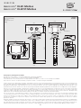
F RHEASGARD® KLGF-Modbus ⁄ KLGFVT-Modbus
Rev. Data - V13
Capteur de débit d’air pour montage en gaine étalonnable
RHEASGARD
®
KLGF - Modbus
avec raccordement Modbus, boîtier plastique résistant aux
chocs avec vis de fermeture rapide, avec presse-étoupe (connecteur M12 en option selon DIN EN 61076-2-101) au choix avec ⁄ sans écran,
pour mesurer la vitesse d’écoulement (0,1...20m/s).
Capteur de débit d’air pour montage en gaine étalonnable
RHEASGARD
®
KLGFVT - Modbus
avec raccordement Modbus, boîtier plastique résistant
aux chocs avec vis de fermeture rapide, avec presse-étoupe (connecteur M12 en option selon DINEN 61076-2-101) au choix avec/ sans écran, pour
mesurer la vitesse d’écoulement (0,1...20 m/s) et la température (0...+50°C). Il est possible d’interroger les paramètres suivants via Modbus:
vitesse d’écoulement, débit volumique (calculé) et température.
Les capteurs de débit sont conçus pour la surveillance ou la commande de débits d’air dans des gaines, sur des ventilateurs, des trappes de réglage,
pour la surveillance en fonction du débit d’air d’humidificateurs et de batteries de chauffe électriques selon DIN57100 partie420 ou pour une utili-
sation en combinaison avec des systèmes à commande numérique directe.
Sonde Modbus innovante avec interface Modbus RS485 à séparation galvanique, résistance de fin de bus commutable, interrupteur DIP pour le
réglage des paramètres du bus et adresse de bus hors tension, LED interne pour l’affichage du télégramme, deux bornes push-in séparées et un
grand écran à trois lignes (éclairé). La sonde est calibrée en usine.
CARACTÉRISTIQUES TECHNIQUES
Alimentation en tension: 24V CA ⁄ CC (± 10%)
Consommation de courant: env. 4VA
Points de données: vitesse d’écoulement [m/s], débit volumique [m³/h], température [°C]
DÉBIT D’AIR
Capteur: calorimétrique, compensation de température, protection contre la rupture du capteur,
avec calibrage manuel du point zéro (via le bouton)
Plage de mesure: 0,1...20m/s
Précision: 0,5m/s + 3%MW
Stabilité à long terme: ± 0,5% Vf par an
Reproductibilité: ± 1,0% Vf
Temps de démarrage: < 2min
Temps de réponse: < 60s
Pontage de démarrage: 0...120s (réglable par potentiomètre)
TEMPÉRATURE
KLGF
(
V
)
T
Capteur: NTC 10k
Plage de mesure: 0...+50 °C
Précision: typique ± 0,5K à +25°C
Protocole de bus: Modbus (mode RTU), plage d’adresses réglable de 0...
247
Filtrage des signaux: valeurs 0...30
Tube de protection:
PLEUROFORM
TM,
matière polyamide (PA6), avec protection anti-torsion, Ø 20mm, NL = 220 mm, vmax = 30m/s (air),
en option sur demande
en acier inoxydable V2A
(1.4301)
,
Ø 16mm
Boîtier: plastique,
résistant aux UV
, matière polyamide, renforcé de billes de verre à 30 %,
avec vis de fermeture rapide (association fente/fente en croix),
coloris blanc signalisation (similaire à RAL 9016), le couvercle de l’écran est transparent!
Dimensions du boîtier: 126x90x50mm (Tyr 2)
Raccordement de câble:
presse-étoupe
en plastique (M 16 x 1,5; avec décharge de traction, interchangeable,
diamètre intérieur max. 10,4mm), en option avec
connecteur M12
selon DINEN 61076-2-101
Raccordement électrique: 0,2 - 1,5mm2, par borne à ressort (push-in)
Raccordement process: avec bride de montage (comprise dans la livraison)
Température ambiante: stockage –20...+50°C; service 0...+50°C
Température moyenne: 0...+70°C
Humidité de l’air admissible: < 98% h.r., air non pollué sans condensation
Classe de protection: III (selon EN60730
Type de protection: boîtier
IP 65
(selon EN60529); capteurs IP20
Normes: conformité CE selon directive «CEM» 2014 ⁄ 30 ⁄ EU, selon EN 61326-1, selon EN 61326-2-3
En option:
écran avec rétro-éclairage,
affichage sur troislignes, découpe env. 70 x 40mm (l x h),
pour l’affichage de la vitesse d’écoulement, du débit volumique et de la température (cyclique)
ou d’un paramètre sélectionnable (statique)

18
F RHEASGARD® KLGF-Modbus ⁄ KLGFVT-Modbus
Rev. Data - V13
PONTAGE AU DÉMARRAGE
Il existe des cas d’application où les moteurs de ventilateurs et les appareils de mesure sont déconnectés et reconnectés.
Lors de la mise en marche, les ventilateurs ont besoin de quelques secondes pour établir un débit.
Pendant ce temps de démarrage, la gestion technique de bâtiment pourrait se mettre en défaut (absence de débit).
Pour le
KLGF-Modbus ainsi que pour le KLGFVT-Modbus
l’activation et le réglage du pontage au démarrage (0...120s) s’effectuent via un potentiomètre.
Après la mise en marche de la tension d’alimentation, un débit de 20m/s est émis pendant ce temps de démarrage.
Après écoulement du temps de démarrage, l’appareil passe en mode de mesure normal.
AUTRES PARAMÈTRES
Pour le
KLGFVT-Modbus
, la température est relevée à l’aide d’un capteur supplémentaire (NTC10k).
De plus, le paramètre «Débit volumique» calculé en interne est mis à disposition.
Cette valeur peut être affichée à l’écran. La bascule se fait par registre.
Type ⁄ WG01 plages de mesure
vitesse
d’écoulement débit volumique température
sortie
écran
référence
KLGF-Modbus
KLGF-Modbus 0,1...20 m/s – – Modbus 1701-4216-0101-000
KLGF-Modbus
LCD
0,1...20 m/s – – Modbus ■1701-4216-1101-000
KLGFVT-Modbus
KLGFVT-Modbus 0,1...20 m/s 0...200.000 m³/h 0...+50 °C Modbus 1701-4216-0401-000
KLGFVT-Modbus
LCD
0,1...20 m/s 0...200.000 m³/h 0...+50 °C Modbus ■1701-4216-1401-000
En option: Raccordement par câble avec
connecteur M12
selon DINEN 61076-2-101 sur demande
ACCESSOIRES
KA2 -
Modbus Adaptateur de communication
(USB/RS485) pour la connexion au système 1906-1200-0000-100
LA -
Modbus
Appareil de terminaison de ligne
(avec résistance de terminaison) en tant que terminaison de bus active
1906-1300-0000-100
MFT-20-K
bride de montage
en matière plastique (comprise dans la livraison) 7000-0031-0000-000

19
F RHEASGARD® KLGF-Modbus ⁄ KLGFVT-Modbus
Rev. Data - V13
Schéma de connexion
Schéma de connexion
Schéma de raccordement
Affectation des plots de connexion
(M12)
KLGF - Modbus
KLGFVT - Modbus
KLGF - Modbus
KLGFVT - Modbus
xx - Modbus
5
1
2
3
4
+UB 24V AC/DC
–UB GND
A
B
Shield
1
2
3
4
5
45°
1
2
3
4
5
45°
1 3
2
4
5
MALE FEMALE
+UB
Modbus A
–UB GND
Modbus B
Shield
zero
set
ok
err.
up
down
address
sb
12345678
ON DIP A
mode
123456
ON DIP B
21 3 4 5
2
1 3 4 5
shield
U+
GND
A
B
Plug for
display
LEDs
zero
set
ok
err.
up
down
address
offsetsb
12345678
ON DIP A
mode
123456
ON DIP B
21 3 4 5
21 3 4 5
shield
U+
GND
A
B
Plug for
display
LEDs
zero
set
ok
err.
up
down
address
offsetsb
12345678
ON DIP A
mode
123456
ON DIP B
21 3 4 5
21 3 4 5
shield
U+
GND
A
B
LEDs
Potentiomètre de réglage
sb
=
pontage au démarrage (min. 0s ... max. 120s)
offset
= température (± 5K)
LEDs
(on = actif)
sb
= pontage au démarrage
ok
= recevoir un protocole sans erreur
err.
= protocole ou somme de contrôle erronés
Touche
zero ⁄ set:
Maintenir enfoncé 2s → Activation du menu sur
l’écran (variantes d’affichage)
Maintenir enfoncé 10s → Définir le point zéro (0m/s)
(la LED-sb clignote pendant le processus et s’éteint
lorsque le point zéro est défini)
up ⁄ down (variantes d’affichage):
Lorsque le menu est actif (touche zero ⁄ set pendant 2s)
,
bascule entre «Débit» (vitesse d’écoulement) et
«Vol» (débit volumique), confirmation avec la touche
zero ⁄ set.
En cas de sélection «Vol»
→ Saisie de la surface en cm² (up ⁄ down)
→ touche zero ⁄ set
→ Saisie de l’unité (up ⁄down)
→ touche zero ⁄ set
Plug for
display

20
F RHEASGARD® KLGF-Modbus ⁄ KLGFVT-Modbus
| Configuration
ADRESSE DU BUS
Adresse du bus
(code binaire, valance réglable de 1 à 247)
MODBUS
Interrupteur DIP [A]
DIP 1 DIP 2 DIP 3 DIP 4 DIP 5 DIP 6 DIP 7 DIP 8
128 64 32 16 8421
O N O N
OFF OFF OFF OFF OFF
O N
L'exemple montre 128 + 64 + 1 = 193 comme adresse Modbus
L'adresse de l'appareil
dans une plage de
1 à 247
(format binaire) est réglée via l'interrupteur DIP [A].
Position interrupteur 1 à 8 – voir tableau au verso !
L'adresse 0 est réservée pour des messages de broadcast, les adresses dépassant 247 ne doivent pas être occupées et sont
ignorées par l'appareil. Les interrupteurs DIP sont codés en binaire avec les valences suivantes :
DIP 1 =
128
............ DIP 1 =
ON
DIP 2 =
64
............ DIP 2 =
ON
DIP 3 = 32 ............ DIP 3 = OFF
DIP 4 = 16 ............ DIP 4 = OFF
DIP 5 = 8 ............ DIP 5 = OFF
DIP 6 = 4 ............ DIP 6 = OFF
DIP 7 = 2 ............ DIP 7 = OFF
DIP 8 =
1
............ DIP 8 =
ON
suit l'adresse Modbus
128 + 64 + 1 = 193
PARAMÈTRES DU BUS
Taux de transfert
(réglable)
DIP
1
DIP
2
MODBUS
Interrupteur DIP [B]
9600 Baud
O N
OFF
19200 Baud
O N O N
38400 Baud OFF
O N
réservé OFF OFF
Parité
(réglable)
DIP
3
Protection par parité
(on/off)
DIP
4
8N1-Modus
(on/off)
DIP
5
Terminaison de
bus
(on/off)
DIP
6
EVEN
(pair)
O N
actif
(1 bit stop)
O N
actif
O N
actif
O N
ODD
(impair)OFF inactif (pas de parité)
(2 bit stop) OFF inactif
(default) OFF inactif OFF
Le
taux de Baud
(vitesse de transfert) est réglé via les pos. 1 et 2 de l'interrupteur DIP [B].
On peut régler 9600 Baud, 19200 Baud ou 38400 Baud – voir tableau !
La
parité
est réglée via la pos. 3 de l'interrupteur DIP [B].
On peut régler
EVEN (paire)
ou
ODD (impaire)
– voir tableau !
La
protection par parité
(sécurité par parité) est activée via la pos. 4 de l'interrupteur DIP [B].
On peut régler une correction d'erreur (sécurisation par parité)
active (1 bit d'arrêt)
ou
inactive (2 bits d'arrêt)
,
c.-à.-d. aucune sécurisation par parité – voir tableau !
Le
mode 8N1
est activé via la pos. 5 de l'interrupteur DIP [B].
Le fonctionnement de la pos. 3 (parité) et de la pos. 4 (protection par parité) de l'interrupteur DIP [B] est ainsi désactivé.
8N1 est réglable en mode
actif
ou
inactif (par défaut)
– voir tableau!
La
terminaison du bus
est activée par la pos. 6 de l'interrupteur DIP [B].
On peut régler
active
(résistance de terminaison de bus de 120 Ohm) ou
inactive
(pas de terminaison de bus) – voir tableau !
En cas de modification des paramètres du bus et de l'adresse du bus, les appareils avec
affichage sur écran
affichent les paramètres correspondants à l'écran pour env. 30 secondes.
AFFICHAGE DE COMMUNICATION
La communication est signalée par deux voyants DEL. Les télégrammes dont la réception est bonne sont signalés
indépendamment de l'adresse de l'appareil par l'allumage du voyant vert. Les télégrammes erronés ou les télégrammes
d'exception Modbus déclenchés sont représentés par l'allumage du voyant rouge.
DIAGNOSTIC
La fonction de diagnostic de défauts est intégrée
La page est en cours de chargement...
La page est en cours de chargement...
La page est en cours de chargement...
La page est en cours de chargement...
La page est en cours de chargement...
La page est en cours de chargement...
La page est en cours de chargement...
La page est en cours de chargement...
La page est en cours de chargement...
La page est en cours de chargement...
La page est en cours de chargement...
La page est en cours de chargement...
-
 1
1
-
 2
2
-
 3
3
-
 4
4
-
 5
5
-
 6
6
-
 7
7
-
 8
8
-
 9
9
-
 10
10
-
 11
11
-
 12
12
-
 13
13
-
 14
14
-
 15
15
-
 16
16
-
 17
17
-
 18
18
-
 19
19
-
 20
20
-
 21
21
-
 22
22
-
 23
23
-
 24
24
-
 25
25
-
 26
26
-
 27
27
-
 28
28
-
 29
29
-
 30
30
-
 31
31
-
 32
32


S+S Regeltechnik RHEASGARD® KLGF-Modbus / KLGFVT-Modbus RHEASGARD® KLGF-Modbus / KLGFVT-Modbus Mode d'emploi
- Taper
- Mode d'emploi
dans d''autres langues
Documents connexes


Autres documents
-
itsensor RHEASREG SW Manuel utilisateur
-
 Rotronic AF1 Short Instruction Manual
-
Vaisala HMD65 Manuel utilisateur
-
Maico PPB 30 K Final Mounting Set Instructions
-
Maico WS 160 Flat Series Operating Instructions Manual
-
Maico 0095.0235 Installation Instructions Manual
-
-
OJ Electronics OJ-Air2FanIO21 Mode d'emploi
-
CARLO GAVAZZI CPA0501LS1X Guide d'installation
-
