

English Quick Start Guide
Air velocity and temperature
transmitter
General features
Features of the housing
Used symbols
For your safety and in order to avoid any damage of the device, please follow the procedure described in
this document and read carefully the notes preceded by the following symbol:
The following symbol will also be used in this document, please read carefully the information notes
indicated after this symbol:
CTV 210-R Connections
Electrical connections as per NFC15-100 standard
All dimensions are in millimeters.
-
+
Alimentation
24 Vdc
N-
L+
N
L
Alimentation 24 Vac
classe II norme EN61558-2-6
N-
L+
Pe
N
L
ou
N
L
Alimentation
N-
L+
Pe
N
L
230 Vac
230 Vac
N
L
Alimentation
100-240 Vac
N-
L+
-+
0-5/10 V 0/4-20 mA
Afcheur régulateur ou
automate type passif
A
-+
0-5/10 V 0/4-20 mA
Afcheur régulateur ou
automate type passif
V
Sortie 4-20 mA
Sortie 0-10 V
-
+
24 Vdc
Power supply
N-
L+
N
L
24 Vac power supply
class II EN61558-2-6 standard
N-
L+
Pe
N
L
or
N
L
Power supply
N-
L+
Pe
N
L
230 Vac
230 Vac
N
L
100-240 Vac
Power supply
N-
L+
-+
0-5/10 V 0/4-20 mA
Regulator display or
PLC/BMS passive type
A
-+
0-5/10 V 0/4-20 mA
Regulator display or
PLC/BMS passive type
V
4-20 mA output
0-10 V output
-
+
Fuente
24 Vdc
N-
L+
N
L
Fuente de alimentación 24 Vac
clase II norma EN61558-2-6
N-
L+
Pe
N
L
o
N
L
Fuente de alim.
N-
L+
Pe
N
L
230 Vac
230 Vac
N
L
Fuente
100-240 Vac
N-
L+
-+
0-5/10 V 0/4-20 mA
PLC/BMS de tipo pasivo
Regulador/display o
PLC/BMS de tipo pasivo
A
-
+
0-5/10 V 0/4-20 mA
Regulador/display o
PLC/BMS de tipo pasivo
V
Salida 4-20 mA
Salida 0-10 V
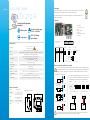
This connection must be made by a formed and qualied technician. To make the connection, the transmitter must not
be energized. Before making the connection, you must rst check the power supply indicated on the transmitter board
(see (b) on “Connections” part). The presence of a switch and a circuit breaker upstream the device is compulsory.
On 100-240 Vac models, if a fuse protection is used for the power line, it is imperative to use delayed-action
fuses in order to absorb the surge of current when rst turned on the transmitter.
The selection of the output signal in voltage (0-10 V or 0-5 V) or in current
(4-20 mA or 0-20 mA)is made via the DIP switch (d) of the electronic board
of the transmitter: put the on-of switches as shown in the table below:
Congurations 4-20 mA 0-10 V 0-5 V 0-20 mA
Combinations
1 2 3 4 1 2 3 4 1 2 3 4 1 2 3 4
1 2 3 4 1 2 3 4 1 2 3 4 1 2 3 4
1 2 3 4 1 2 3 4 1 2 3 4 1 2 3 4
1 2 3 4 1 2 3 4 1 2 3 4 1 2 3 4
• Connection of the output in current
4-20 mA:
• Connection of output in voltage
0-10 V:
• For transmitters with 24 Vdc power supply:
• For transmitters with 24 Vac power supply:
• For transmitters with 100-240 Vac power supply:
-
+
Alimentation
24 Vdc
N-
L+
N
L
Alimentation 24 Vac
classe II norme EN61558-2-6
N-
L+
Pe
N
L
ou
N
L
Alimentation
N-
L+
Pe
N
L
230 Vac
230 Vac
N
L
Alimentation
100-240 Vac
N-
L+
-+
0-5/10 V 0/4-20 mA
Afcheur régulateur ou
automate type passif
A
-+
0-5/10 V 0/4-20 mA
Afcheur régulateur ou
automate type passif
V
Sortie 4-20 mA
Sortie 0-10 V
-
+
24 Vdc
Power supply
N-
L+
N
L
24 Vac power supply
class II EN61558-2-6 standard
N-
L+
Pe
N
L
or
N
L
Power supply
N-
L+
Pe
N
L
230 Vac
230 Vac
N
L
100-240 Vac
Power supply
N-
L+
-+
0-5/10 V 0/4-20 mA
Regulator display or
PLC/BMS passive type
A
-+
0-5/10 V 0/4-20 mA
Regulator display or
PLC/BMS passive type
V
4-20 mA output
0-10 V output
-
+
Fuente
24 Vdc
N-
L+
N
L
Fuente de alimentación 24 Vac
clase II norma EN61558-2-6
N-
L+
Pe
N
L
o
N
L
Fuente de alim.
N-
L+
Pe
N
L
230 Vac
230 Vac
N
L
Fuente
100-240 Vac
N-
L+
-+
0-5/10 V 0/4-20 mA
PLC/BMS de tipo pasivo
Regulador/display o
PLC/BMS de tipo pasivo
A
-
+
0-5/10 V 0/4-20 mA
Regulador/display o
PLC/BMS de tipo pasivo
V
Salida 4-20 mA
Salida 0-10 V
-
+
Alimentation
24 Vdc
N-
L+
N
L
Alimentation 24 Vac
classe II norme EN61558-2-6
N-
L+
Pe
N
L
ou
N
L
Alimentation
N-
L+
Pe
N
L
230 Vac
230 Vac
N
L
Alimentation
100-240 Vac
N-
L+
-+
0-5/10 V 0/4-20 mA
Afcheur régulateur ou
automate type passif
A
-+
0-5/10 V 0/4-20 mA
Afcheur régulateur ou
automate type passif
V
Sortie 4-20 mA
Sortie 0-10 V
-
+
24 Vdc
Power supply
N-
L+
N
L
24 Vac power supply
class II EN61558-2-6 standard
N-
L+
Pe
N
L
or
N
L
Power supply
N-
L+
Pe
N
L
230 Vac
230 Vac
N
L
100-240 Vac
Power supply
N-
L+
-+
0-5/10 V 0/4-20 mA
Regulator display or
PLC/BMS passive type
A
-+
0-5/10 V 0/4-20 mA
Regulator display or
PLC/BMS passive type
V
4-20 mA output
0-10 V output
-
+
Fuente
24 Vdc
N-
L+
N
L
Fuente de alimentación 24 Vac
clase II norma EN61558-2-6
N-
L+
Pe
N
L
o
N
L
Fuente de alim.
N-
L+
Pe
N
L
230 Vac
230 Vac
N
L
Fuente
100-240 Vac
N-
L+
-+
0-5/10 V 0/4-20 mA
PLC/BMS de tipo pasivo
Regulador/display o
PLC/BMS de tipo pasivo
A
-
+
0-5/10 V 0/4-20 mA
Regulador/display o
PLC/BMS de tipo pasivo
V
Salida 4-20 mA
Salida 0-10 V
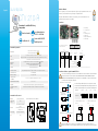
Two 4-wire analogue output
0-5/10 V or 0/4-20 mA
Airow function
ABS V0 IP65 housing,
optional display
2 relay outputs
0-5 / 10 V
4-20 mA
Power supply 24 Vac / Vdc ±10%. 100-240 Vac, 50-60 Hz
Warning: risk of electric shock
Output 2 x 4-20 mA or 2 x 0-20 mA or 2 x 0-5 V or 2 x 0-10 V (4 wires)
Common mode voltage <30 Vac. Maximum load: 500 Ohms (0/4-20 mA). Minimum load: 1 K Ohms (0-5/10 V)
Relay outputs 2 changeover relays 3 A / 230 V. NO : 5A / NC: 3A / 240 Vac
Galvanic isolation
Inputs and outputs (models 100-240 Vac). Device fully protected by
DOUBLE ISOLATION or REINFORCED ISOLATION
Outputs (models 24 Vac/Vdc)
Consumption CTV210-B: 6 VA. CTV210-H: 8 VA
Electrical connection Screw terminal block for cable 2.5 mm². Carried out according to the code of good practice
PC communication USB-Mini Din cable
Environment Air and neutral gases
Conditions of use (°C/%RH/m) From -10 to +50 °C. In non-condensing condition. From 0 to 2000 m.
Storage temperature From -10 to +70 °C
Security Protection class II; Pollution degree 2; Overvoltage category 2 (OVCII)
European directives 2014/30/EU EMC; 2014/35/EU Low Voltage; 2011/65/EU RoHS II; 2012/19/EU WEEE
Material ABS V0 as per UL94
Protection IP65
Display
75 x 40 mm, LCD 20 digits 2 lines.
Height of digits: Values: 10 mm;
Units: 5 mm
Cable gland For cables Ø 8 mm maximum
Weight 340 g
115
125
59
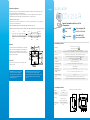
CTV210-XXX-S-R
Power supply: 100-240 Vac
50-60 Hz 8 VA
Output: 0/4...20 mA / 0...5/10 V
100-240 Vac 24 Vac/Vdc
CTV210-XXX-S-R
Power supply: 24 Vac/Vdc ±10%
50-60 Hz 6 VA
Output: 0/4...20 mA / 0...5/10 V
Type d'alimentation (b) précisée sur l'étiquette
sur le côté du capteur
1
2
3
45
7
6
Sortie analogique 1
(out 1)
0-5/10 V – Tension
GND – Masse
0/4-20 mA – Courant
Sortie analogique 2
(out 2)
0-5/10 V – Tension
GND – Masse
0/4-20 mA – Courant
(a) (c) ou
Pour les modèles en
alimentation 24 Vdc
-
+
(c) ou
Pour les modèles en
alimentation 24 Vac
Neutre (N)~
Phase (L)~
(c)
Pour les modèles en
alimentation 100-240 Vac
Neutre (N)~
Phase (L)~
Relais 1 et 2
COM: commun
NC: normalement fermé
NO: normalement ouvert
Terre fonctionnelle
*Fusible uniquement présent sur les modèles 100-240 Vac.
Tout changement de fusible doit être réalisé appareil hors tension en utilisant un fusible TR5 630 mA 250 V.
CTV210-XXX-S-R
Power supply: 100-240 Vac
50-60 Hz 8 VA
Output: 0/4...20 mA / 0...5/10 V
100-240 Vac 24 Vac/Vdc
CTV210-XXX-S-R
Power supply: 24 Vac/Vdc ±10%
50-60 Hz 6 VA
Output: 0/4...20 mA / 0...5/10 V
Power supply type (b) specied on the label
on the side of the transmitter
1
2
3
45
7
6
Analogue output 1
(out 1)
0-5/10 V – Voltage
GND – Ground
0/4-20 mA – Current
Analogue output 2
(out 2)
0-5/10 V – Voltage
GND – Ground
0/4-20 mA – Current
(a) (c) or
For 24Vdc power
supply models
-
+
(c) or
For 24Vac power
supply models
Neutral (N)~
Phase (L)~
(c)
For 100-240 Vac
power supply models
Neutral (N)~
Phase (L)~
Relays 1 and 2
COM: common
NC: normaly closed
NO: normaly opened
Operating grounding
*Fuse present only for 100-240 Vac models.
Every fuse replacement must be performed witht a power off device using a TR5 630 mA 250 V fuse.
CTV210-XXX-S-R
Alimentación: 100-240 Vac
50-60 Hz 8 VA
Salida: 0/4...20 mA / 0...5/10 V
100-240 Vac 24 Vac/Vdc
CTV210-XXX-S-R
Alimentación: 24 Vac/Vdc ±10%
50-60 Hz 6 VA
Salida: 0/4...20 mA / 0...5/10 V
Tipo de alimentación (b) especicada en la
etiqueta lateral del transmisor
1
2
3
45
7
6
Salida analógica 1
(out 1)
0-5/10 V – Voltaje
GND – Tierra
0/4-20 mA – Corriente
Salida analógica 2
(out 2)
0-5/10 V – Voltaje
GND – Tierra
0/4-20 mA – Corriente
(a) (c) or
Alimentación a
24Vdc
-
+
(c) or
Alimentación a
24Vac
Neutro (N)~
Fase (L)~
(c)
Alimentación
100-240 Vac
Neutro (N)~
Fase (L)~
Relés 1 y 2
COM: común
NC: normalmente cerrado
NO: Normalmente abierto
Toma a tierra
*Fusible solo en modelos con alimentación 100-240 Vac.
El remplazo del fusible debe ser efectuado con el dispositivo con la alimentación desconectada usando un fusible TR5 630 mA 250 V .
1. DIP switch (d)
2. LCC-S software connection
3. Relays
4. Analogue outputs (a)
5. F3.20* fuse
6. Power supply terminal block (c)
7. Cable glands

Accessories
Maintenance: please avoid any aggressive
solvents. Please protect the transmitter
and its probes from any cleaning product
containing formalin, that may be used for
cleaning rooms or ducts.
Precautions for use: please always use the device
in accordance with its intended use and within
parameters described in the technical features in order
not to compromise the protection ensured by the
device.
Please refer to the data sheet to get more information about
available accessories.
Français Guide rapide
Transmitters conguration
Mounting
It is possible on the class 210 to congure all the parameters managed by the transmitter: units, measuring ranges, outputs,
channels, calculation functions, etc, via different methods:
• Keypad for models with display: a code-locking system allows to secure the installation (See class 210 user manual).
• Software (optional) on all models. Simple user-friendly conguration. See LCC-SD user manual.
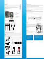
Congurable analogue output:
Range with central zero (-50/0/+50 Pa), with offset zero (-300/0/+70 Pa) or standard range (0/+100 Pa), it is possible to
congure your own intermediate ranges.
Caution: the minimum difference between the high range and the low range is 20.
Congure the range according to your needs: outputs are automatically adjusted to the new measuring range
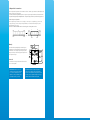
To mount the transmitter, mount the ABS plate on the wall (drilling:
Ø6 mm, screws and pins are supplied). Insert the transmitter on the
xing plate (see A on the drawing beside). Rotate the housing in
clockwise direction until you hear a “click” which conrms that the
transmitter is correctly installed.
0 m/s
0 V
4 mA
15 30 m/s
10 V
20 mA
Nouvelle
échelle
0 m/s
0 V
4 mA
530 m/s
10 V
20 mA
25
0 m/s
0 V
4 mA
15 30 m/s
10 V
20 mA
New
range
0 m/s
0 V
4 mA
530 m/s
10 V
20 mA
25
0 m/s
0 V
4 mA
15 30 m/s
10 V
20 mA
Nuevo
rango
0 m/s
0 V
4 mA
530 m/s
10 V
20 mA
25
2
Capteur / transmetteur de vitesse de l'air
et température
Caractéristiques générales
Caractéristiques du boîtier
CTV 210-R
Les dimensions sont exprimées en millimètres.
Sortie analogique 4 ls
0-5/10 V ou 0/4-20 mA
Fonction débit
d'air
Boîtier ABS V0 IP65,
avec ou sans afcheur
2 sorties relais
0-5 / 10 V
4-20 mA
115
125
59
Alimentation 24 Vac/Vdc ±10%. 100-240 Vac, 50-60 Hz
Attention risque choc électrique
Sortie 2 x 4-20 mA ou 2 x 0-20 mA ou 2 x 0-5 V ou 2 x 0-10 V (4 ls)
Tension de mode commun < 30 VAC. Charge maximale: 500 Ohms (0/4-20 mA). Charge minimale: 1 K Ohms (0-5/10 V)
Sorties relais 2 relais inverseurs. NO (normalement ouvert) : 5 A/NC (normalement fermé) : 3 A/240 Vac
Isolation
galvanique
Entrées et sorties (modèles 100-240 Vac). Appareil entièrement protégé par
DOUBLE ISOLATION ou ISOLATION RENFORCÉE
Sorties (modèles 24 Vac/Vdc)
Consommation CTV210-B: 6 VA. CTV210-H: 8 VA
Raccordement électrique Bornier à vis pour câble 2.5 mm². Réalisé suivant les règles de l’art
Communication PC Câble USB-Mini Din
Environnement Air et gaz neutres
Conditions d’utilisation
(°C/%HR/m) De -10 à +50 °C. En condition de non condensation. De 0 à 2000 m.
Température de stockage De -10 à +70 °C
Sécurité Classe de protection II. Degré de pollution 2. Catégorie de surtension 2 (OVCII)
Directives européennes 2014/30/UE CEM, 2014/35/UE Basse Tension, 2011/65/UE RoHS II, 2012/19/UE DEEE
Matière ABS V0 selon UL94
Indice de
protection IP65
Afcheur
75 x 40 mm, LCD 19 digits 2 lignes
Hauteur des caractères :
Valeurs: 10 mm; Unités: 5 mm
Presse étoupe Pour câbles Ø 8 mm maximum
Poids 340 g

Accessoires
Entretien : éviter tous les solvants
agressifs. Lors du nettoyage à base de
produits formolés (pièces ou conduits),
protéger l’appareil.
Précautions d'utilisation : veillez à toujours utiliser
l’appareil conformément à l’usage prévu et dans les
limites des paramètres décrits dans les caractéristiques
techniques an de ne pas compromettre la protection
assurée par l’appareil.
Veuillez vous référer à la che technique pour obtenir plus
d'informations sur les accessoires disponibles.
Conguration des capteurs
Montage
Il est possible sur la classe 210 de congurer en toute liberté l’ensemble des paramètres gérés par le capteur : les unités, les
échelles de mesure, les sorties, les voies, les fonctions de calcul, etc. grâce à différents procédés :
• Par clavier pour les modèles avec afcheurs : un verrouillage du clavier par code permet de garantir la sécurité des installations (voir
la notice d’utilisation).
• Par logiciel (en option) pour tous les modèles : ce mode permet une conguration plus souple. Voir la notice d’utilisation du LCC-S.
Sorties analogiques congurables :
Échelle à zéro central (-50/0/+50 Pa), à zéro décalé (-300/0/+70 Pa) ou échelle standard (0/+100 Pa), il est possible de
congurer vos propres échelles intermédiaires.
Attention : La différence minimum entre l’échelle haute et l’échelle basse est de 20.
Échelles congurables selon vos besoins : les sorties sont automatiquement ajustées à la nouvelle échelle
Pour réaliser le montage mural, xer la plaque ABS au mur (perçage
Ø6 mm, vis et chevilles fournies). Insérer le capteur dans la plaque de
xation (aux points A sur le schéma) en l’inclinant à 30°. Faire pivoter
le boîtier dans le sens des aiguilles d’une montre jusqu’à l’obtention
d’un clipage ferme.
Symboles utilisés
Pour votre sécurité et an d’éviter tout endommagement de l’appareil, veuillez suivre la procédure décrite
dans ce document et lire attentivement les notes précédées du symbole suivant :
Le symbole suivant sera également utilisé dans ce document. Veuillez lire attentivement les notes
d’informations indiquées après ce symbole.
Connectiques
Raccordements électriques suivant normes NFC15-100
CTV210-XXX-S-R
Power supply: 100-240 Vac
50-60 Hz 8 VA
Output: 0/4...20 mA / 0...5/10 V
100-240 Vac 24 Vac/Vdc
CTV210-XXX-S-R
Power supply: 24 Vac/Vdc ±10%
50-60 Hz 6 VA
Output: 0/4...20 mA / 0...5/10 V
Type d'alimentation (b) précisée sur l'étiquette
sur le côté du capteur
1
2
3
45
7
6
Sortie analogique 1
(out 1)
0-5/10 V – Tension
GND – Masse
0/4-20 mA – Courant
Sortie analogique 2
(out 2)
0-5/10 V – Tension
GND – Masse
0/4-20 mA – Courant
(a) (c) ou
Pour les modèles en
alimentation 24 Vdc
-
+
(c) ou
Pour les modèles en
alimentation 24 Vac
Neutre (N)~
Phase (L)~
(c)
Pour les modèles en
alimentation 100-240 Vac
Neutre (N)~
Phase (L)~
Relais 1 et 2
COM: commun
NC: normalement fermé
NO: normalement ouvert
Terre fonctionnelle
*Fusible uniquement présent sur les modèles 100-240 Vac.
Tout changement de fusible doit être réalisé appareil hors tension en utilisant un fusible TR5 630 mA 250 V.
CTV210-XXX-S-R
Power supply: 100-240 Vac
50-60 Hz 8 VA
Output: 0/4...20 mA / 0...5/10 V
100-240 Vac 24 Vac/Vdc
CTV210-XXX-S-R
Power supply: 24 Vac/Vdc ±10%
50-60 Hz 6 VA
Output: 0/4...20 mA / 0...5/10 V
Power supply type (b) specied on the label
on the side of the transmitter
1
2
3
45
7
6
Analogue output 1
(out 1)
0-5/10 V – Voltage
GND – Ground
0/4-20 mA – Current
Analogue output 2
(out 2)
0-5/10 V – Voltage
GND – Ground
0/4-20 mA – Current
(a) (c) or
For 24Vdc power
supply models
-
+
(c) or
For 24Vac power
supply models
Neutral (N)~
Phase (L)~
(c)
For 100-240 Vac
power supply models
Neutral (N)~
Phase (L)~
Relays 1 and 2
COM: common
NC: normaly closed
NO: normaly opened
Operating grounding
*Fuse present only for 100-240 Vac models.
Every fuse replacement must be performed witht a power off device using a TR5 630 mA 250 V fuse.
CTV210-XXX-S-R
Alimentación: 100-240 Vac
50-60 Hz 8 VA
Salida: 0/4...20 mA / 0...5/10 V
100-240 Vac 24 Vac/Vdc
CTV210-XXX-S-R
Alimentación: 24 Vac/Vdc ±10%
50-60 Hz 6 VA
Salida: 0/4...20 mA / 0...5/10 V
Tipo de alimentación (b) especicada en la
etiqueta lateral del transmisor
1
2
3
45
7
6
Salida analógica 1
(out 1)
0-5/10 V – Voltaje
GND – Tierra
0/4-20 mA – Corriente
Salida analógica 2
(out 2)
0-5/10 V – Voltaje
GND – Tierra
0/4-20 mA – Corriente
(a) (c) or
Alimentación a
24Vdc
-
+
(c) or
Alimentación a
24Vac
Neutro (N)~
Fase (L)~
(c)
Alimentación
100-240 Vac
Neutro (N)~
Fase (L)~
Relés 1 y 2
COM: común
NC: normalmente cerrado
NO: Normalmente abierto
Toma a tierra
*Fusible solo en modelos con alimentación 100-240 Vac.
El remplazo del fusible debe ser efectuado con el dispositivo con la alimentación desconectada usando un fusible TR5 630 mA 250 V .
1. Switch (d)
2. Connecteur logiciel LCC-S
3. Relais
4. Sorties analogiques (a)
5. Fusible F3.20*
6. Bornier d’alimentation (c)
7. Presse-étoupes 0 m/s
0 V
4 mA
15 30 m/s
10 V
20 mA
Nouvelle
échelle
0 m/s
0 V
4 mA
530 m/s
10 V
20 mA
25
0 m/s
0 V
4 mA
15 30 m/s
10 V
20 mA
New
range
0 m/s
0 V
4 mA
530 m/s
10 V
20 mA
25
0 m/s
0 V
4 mA
15 30 m/s
10 V
20 mA
Nuevo
rango
0 m/s
0 V
4 mA
530 m/s
10 V
20 mA
25
2
-
+
Alimentation
24 Vdc
N-
L+
N
L
Alimentation 24 Vac
classe II norme EN61558-2-6
N-
L+
Pe
N
L
ou
N
L
Alimentation
N-
L+
Pe
N
L
230 Vac
230 Vac
N
L
Alimentation
100-240 Vac
N-
L+
-+
0-5/10 V 0/4-20 mA
Afcheur régulateur ou
automate type passif
A
-+
0-5/10 V 0/4-20 mA
Afcheur régulateur ou
automate type passif
V
Sortie 4-20 mA
Sortie 0-10 V
-
+
24 Vdc
Power supply
N-
L+
N
L
24 Vac power supply
class II EN61558-2-6 standard
N-
L+
Pe
N
L
or
N
L
Power supply
N-
L+
Pe
N
L
230 Vac
230 Vac
N
L
100-240 Vac
Power supply
N-
L+
-+
0-5/10 V 0/4-20 mA
Regulator display or
PLC/BMS passive type
A
-+
0-5/10 V 0/4-20 mA
Regulator display or
PLC/BMS passive type
V
4-20 mA output
0-10 V output
-
+
Fuente
24 Vdc
N-
L+
N
L
Fuente de alimentación 24 Vac
clase II norma EN61558-2-6
N-
L+
Pe
N
L
o
N
L
Fuente de alim.
N-
L+
Pe
N
L
230 Vac
230 Vac
N
L
Fuente
100-240 Vac
N-
L+
-+
0-5/10 V 0/4-20 mA
PLC/BMS de tipo pasivo
Regulador/display o
PLC/BMS de tipo pasivo
A
-
+
0-5/10 V 0/4-20 mA
Regulador/display o
PLC/BMS de tipo pasivo
V
Salida 4-20 mA
Salida 0-10 V
Seul un technicien formé et qualié peut réaliser cette opération. Pour réaliser le raccordement, l’appareil doit être
HORS-TENSION. Avant de procéder au raccordement, vérier le type d’alimentation du capteur indiquée sur l’étiquette
sur le côté du capteur (b). La présence d’un interrupteur ou d’un disjoncteur en amont de l’appareil est obligatoire.
Sur les modèles 100-240 Vac, si une protection par fusible de la ligne d’alimentation est utilisée, il est impératif
d’utiliser des fusibles temporisés an d’absorber le pic de courant à la mise sous tension du capteur.
La sélection du signal de sortie en tension (0-10 V ou 0-5 V) ou en courant
(4-20 mA ou 0-20 mA) se fait avec le switch (d) de la carte électronique du
capteur en disposant les interrupteurs de la manière suivante :
Congurations 4-20 mA 0-10 V 0-5 V 0-20 mA
Combinaisons
1 2 3 4 1 2 3 4 1 2 3 4 1 2 3 4
1 2 3 4 1 2 3 4 1 2 3 4 1 2 3 4
1 2 3 4 1 2 3 4 1 2 3 4 1 2 3 4
1 2 3 4 1 2 3 4 1 2 3 4 1 2 3 4
• Raccordement de la sortie courant
4-20 mA :
• Raccordement de la sortie
tension 0-10 V :
• Pour les modèles avec une alimentation en 24 Vdc :
• Pour les modèles avec une alimentation en 24 Vac :
• Pour les modèles avec une alimentation en
100-240 Vac :
-
+
Alimentation
24 Vdc
N-
L+
N
L
Alimentation 24 Vac
classe II norme EN61558-2-6
N-
L+
Pe
N
L
ou
N
L
Alimentation
N-
L+
Pe
N
L
230 Vac
230 Vac
N
L
Alimentation
100-240 Vac
N-
L+
-+
0-5/10 V 0/4-20 mA
Afcheur régulateur ou
automate type passif
A
-+
0-5/10 V 0/4-20 mA
Afcheur régulateur ou
automate type passif
V
Sortie 4-20 mA
Sortie 0-10 V
-
+
24 Vdc
Power supply
N-
L+
N
L
24 Vac power supply
class II EN61558-2-6 standard
N-
L+
Pe
N
L
or
N
L
Power supply
N-
L+
Pe
N
L
230 Vac
230 Vac
N
L
100-240 Vac
Power supply
N-
L+
-+
0-5/10 V 0/4-20 mA
Regulator display or
PLC/BMS passive type
A
-+
0-5/10 V 0/4-20 mA
Regulator display or
PLC/BMS passive type
V
4-20 mA output
0-10 V output
-
+
Fuente
24 Vdc
N-
L+
N
L
Fuente de alimentación 24 Vac
clase II norma EN61558-2-6
N-
L+
Pe
N
L
o
N
L
Fuente de alim.
N-
L+
Pe
N
L
230 Vac
230 Vac
N
L
Fuente
100-240 Vac
N-
L+
-+
0-5/10 V 0/4-20 mA
PLC/BMS de tipo pasivo
Regulador/display o
PLC/BMS de tipo pasivo
A
-
+
0-5/10 V 0/4-20 mA
Regulador/display o
PLC/BMS de tipo pasivo
V
Salida 4-20 mA
Salida 0-10 V
-
+
Alimentation
24 Vdc
N-
L+
N
L
Alimentation 24 Vac
classe II norme EN61558-2-6
N-
L+
Pe
N
L
ou
N
L
Alimentation
N-
L+
Pe
N
L
230 Vac
230 Vac
N
L
Alimentation
100-240 Vac
N-
L+
-+
0-5/10 V 0/4-20 mA
Afcheur régulateur ou
automate type passif
A
-+
0-5/10 V 0/4-20 mA
Afcheur régulateur ou
automate type passif
V
Sortie 4-20 mA
Sortie 0-10 V
-
+
24 Vdc
Power supply
N-
L+
N
L
24 Vac power supply
class II EN61558-2-6 standard
N-
L+
Pe
N
L
or
N
L
Power supply
N-
L+
Pe
N
L
230 Vac
230 Vac
N
L
100-240 Vac
Power supply
N-
L+
-+
0-5/10 V 0/4-20 mA
Regulator display or
PLC/BMS passive type
A
-+
0-5/10 V 0/4-20 mA
Regulator display or
PLC/BMS passive type
V
4-20 mA output
0-10 V output
-
+
Fuente
24 Vdc
N-
L+
N
L
Fuente de alimentación 24 Vac
clase II norma EN61558-2-6
N-
L+
Pe
N
L
o
N
L
Fuente de alim.
N-
L+
Pe
N
L
230 Vac
230 Vac
N
L
Fuente
100-240 Vac
N-
L+
-+
0-5/10 V 0/4-20 mA
PLC/BMS de tipo pasivo
Regulador/display o
PLC/BMS de tipo pasivo
A
-
+
0-5/10 V 0/4-20 mA
Regulador/display o
PLC/BMS de tipo pasivo
V
Salida 4-20 mA
Salida 0-10 V

Español Guía rápida Símbolos utilizados
Para su seguridad y con el n de evitar cualquier daño al aparato, siga el procedimiento descrito en este
documento y lea atentamente las notas precedidas por el siguiente símbolo:
El siguiente símbolo también se utilizará en este documento, por favor, lea atentamente las notas
informativas indicadas después de este símbolo:
Conexiones
Conexiones eléctricas – según la norma NFC15-100
-
+
Alimentation
24 Vdc
N-
L+
N
L
Alimentation 24 Vac
classe II norme EN61558-2-6
N-
L+
Pe
N
L
ou
N
L
Alimentation
N-
L+
Pe
N
L
230 Vac
230 Vac
N
L
Alimentation
100-240 Vac
N-
L+
-+
0-5/10 V 0/4-20 mA
Afcheur régulateur ou
automate type passif
A
-+
0-5/10 V 0/4-20 mA
Afcheur régulateur ou
automate type passif
V
Sortie 4-20 mA
Sortie 0-10 V
-
+
24 Vdc
Power supply
N-
L+
N
L
24 Vac power supply
class II EN61558-2-6 standard
N-
L+
Pe
N
L
or
N
L
Power supply
N-
L+
Pe
N
L
230 Vac
230 Vac
N
L
100-240 Vac
Power supply
N-
L+
-+
0-5/10 V 0/4-20 mA
Regulator display or
PLC/BMS passive type
A
-+
0-5/10 V 0/4-20 mA
Regulator display or
PLC/BMS passive type
V
4-20 mA output
0-10 V output
-
+
Fuente
24 Vdc
N-
L+
N
L
Fuente de alimentación 24 Vac
clase II norma EN61558-2-6
N-
L+
Pe
N
L
o
N
L
Fuente de alim.
N-
L+
Pe
N
L
230 Vac
230 Vac
N
L
Fuente
100-240 Vac
N-
L+
-+
0-5/10 V 0/4-20 mA
PLC/BMS de tipo pasivo
Regulador/display o
PLC/BMS de tipo pasivo
A
-
+
0-5/10 V 0/4-20 mA
Regulador/display o
PLC/BMS de tipo pasivo
V
Salida 4-20 mA
Salida 0-10 V
Solo un técnico cualicado puede efectuar estas conexiones. Debe llevar a cabo esta instalación cuando el instrumento
no tenga tensión. Antes de efectuar cualquier conexión, DEBE VERIFICARSE EL TIPO DE ALIMENTACIÓN QUE SE
INDICA EN LA PLACA DEL TRANSMISOR (vea (b) en el apartado de « CONEXIONES »). La presencia de un interruptor
y un disruptor antes del dispositivo es obligatorio.
En modelos de alimentación 100-240 Vac, si se usa un fusible para la protección de la línea de potencia, es
imperativo usar fusibles con acción retardada para absorber el pico de corriente presente al encender el transmisor.
La selección del tipo de salida analógica (0-10 V, 0-5 V, 4-20 mA ó 0-20 mA)
se efectúa mediante los interruptores DIP switch (d) de la placa electrónica del
transmisor. Coloque los interruptores tal y como se indica en la tabla siguiente :
Conguración 4-20 mA 0-10 V 0-5 V 0-20 mA
Combinaciones
1 2 3 4
1 2 3 4 1 2 3 4 1 2 3 4
1 2 3 4
1 2 3 4
1 2 3 4 1 2 3 4
1 2 3 4 1 2 3 4
1 2 3 4
1 2 3 4
1 2 3 4 1 2 3 4 1 2 3 4
1 2 3 4
• Conexión de la salida en corriente
4-20 mA :
• Conexión de la salida en voltaje
0-10 V :
• Para transmisores con alimentación 24Vdc :
• Para transmisores con alimentación 24 Vac :
• Para transmisores con alimentación 100-240 Vac :
-
+
Alimentation
24 Vdc
N-
L+
N
L
Alimentation 24 Vac
classe II norme EN61558-2-6
N-
L+
Pe
N
L
ou
N
L
Alimentation
N-
L+
Pe
N
L
230 Vac
230 Vac
N
L
Alimentation
100-240 Vac
N-
L+
-+
0-5/10 V 0/4-20 mA
Afcheur régulateur ou
automate type passif
A
-+
0-5/10 V 0/4-20 mA
Afcheur régulateur ou
automate type passif
V
Sortie 4-20 mA
Sortie 0-10 V
-
+
24 Vdc
Power supply
N-
L+
N
L
24 Vac power supply
class II EN61558-2-6 standard
N-
L+
Pe
N
L
or
N
L
Power supply
N-
L+
Pe
N
L
230 Vac
230 Vac
N
L
100-240 Vac
Power supply
N-
L+
-+
0-5/10 V 0/4-20 mA
Regulator display or
PLC/BMS passive type
A
-+
0-5/10 V 0/4-20 mA
Regulator display or
PLC/BMS passive type
V
4-20 mA output
0-10 V output
-
+
Fuente
24 Vdc
N-
L+
N
L
Fuente de alimentación 24 Vac
clase II norma EN61558-2-6
N-
L+
Pe
N
L
o
N
L
Fuente de alim.
N-
L+
Pe
N
L
230 Vac
230 Vac
N
L
Fuente
100-240 Vac
N-
L+
-+
0-5/10 V 0/4-20 mA
PLC/BMS de tipo pasivo
Regulador/display o
PLC/BMS de tipo pasivo
A
-
+
0-5/10 V 0/4-20 mA
Regulador/display o
PLC/BMS de tipo pasivo
V
Salida 4-20 mA
Salida 0-10 V
-
+
Alimentation
24 Vdc
N-
L+
N
L
Alimentation 24 Vac
classe II norme EN61558-2-6
N-
L+
Pe
N
L
ou
N
L
Alimentation
N-
L+
Pe
N
L
230 Vac
230 Vac
N
L
Alimentation
100-240 Vac
N-
L+
-+
0-5/10 V 0/4-20 mA
Afcheur régulateur ou
automate type passif
A
-+
0-5/10 V 0/4-20 mA
Afcheur régulateur ou
automate type passif
V
Sortie 4-20 mA
Sortie 0-10 V
-
+
24 Vdc
Power supply
N-
L+
N
L
24 Vac power supply
class II EN61558-2-6 standard
N-
L+
Pe
N
L
or
N
L
Power supply
N-
L+
Pe
N
L
230 Vac
230 Vac
N
L
100-240 Vac
Power supply
N-
L+
-+
0-5/10 V 0/4-20 mA
Regulator display or
PLC/BMS passive type
A
-+
0-5/10 V 0/4-20 mA
Regulator display or
PLC/BMS passive type
V
4-20 mA output
0-10 V output
-
+
Fuente
24 Vdc
N-
L+
N
L
Fuente de alimentación 24 Vac
clase II norma EN61558-2-6
N-
L+
Pe
N
L
o
N
L
Fuente de alim.
N-
L+
Pe
N
L
230 Vac
230 Vac
N
L
Fuente
100-240 Vac
N-
L+
-+
0-5/10 V 0/4-20 mA
PLC/BMS de tipo pasivo
Regulador/display o
PLC/BMS de tipo pasivo
A
-
+
0-5/10 V 0/4-20 mA
Regulador/display o
PLC/BMS de tipo pasivo
V
Salida 4-20 mA
Salida 0-10 V
Transmisor de velocidad del aire y
temperatura
Características generales
Características de la carcasa
CTV 210-R
Todas las dimensiones están en milímetros.
Dos salidas analógicas
0-5/10 V ó 0/4-20 mA
Función de caudal
Carcasa de ABS V0 IP65.
Pantalla opcional.
2 salidas de relé
0-5 / 10 V
4-20 mA
115
125
59
CTV210-XXX-S-R
Power supply: 100-240 Vac
50-60 Hz 8 VA
Output: 0/4...20 mA / 0...5/10 V
100-240 Vac 24 Vac/Vdc
CTV210-XXX-S-R
Power supply: 24 Vac/Vdc ±10%
50-60 Hz 6 VA
Output: 0/4...20 mA / 0...5/10 V
Type d'alimentation (b) précisée sur l'étiquette
sur le côté du capteur
1
2
3
45
7
6
Sortie analogique 1
(out 1)
0-5/10 V – Tension
GND – Masse
0/4-20 mA – Courant
Sortie analogique 2
(out 2)
0-5/10 V – Tension
GND – Masse
0/4-20 mA – Courant
(a) (c) ou
Pour les modèles en
alimentation 24 Vdc
-
+
(c) ou
Pour les modèles en
alimentation 24 Vac
Neutre (N)~
Phase (L)~
(c)
Pour les modèles en
alimentation 100-240 Vac
Neutre (N)~
Phase (L)~
Relais 1 et 2
COM: commun
NC: normalement fermé
NO: normalement ouvert
Terre fonctionnelle
*Fusible uniquement présent sur les modèles 100-240 Vac.
Tout changement de fusible doit être réalisé appareil hors tension en utilisant un fusible TR5 630 mA 250 V.
CTV210-XXX-S-R
Power supply: 100-240 Vac
50-60 Hz 8 VA
Output: 0/4...20 mA / 0...5/10 V
100-240 Vac 24 Vac/Vdc
CTV210-XXX-S-R
Power supply: 24 Vac/Vdc ±10%
50-60 Hz 6 VA
Output: 0/4...20 mA / 0...5/10 V
Power supply type (b) specied on the label
on the side of the transmitter
1
2
3
45
7
6
Analogue output 1
(out 1)
0-5/10 V – Voltage
GND – Ground
0/4-20 mA – Current
Analogue output 2
(out 2)
0-5/10 V – Voltage
GND – Ground
0/4-20 mA – Current
(a) (c) or
For 24Vdc power
supply models
-
+
(c) or
For 24Vac power
supply models
Neutral (N)~
Phase (L)~
(c)
For 100-240 Vac
power supply models
Neutral (N)~
Phase (L)~
Relays 1 and 2
COM: common
NC: normaly closed
NO: normaly opened
Operating grounding
*Fuse present only for 100-240 Vac models.
Every fuse replacement must be performed witht a power off device using a TR5 630 mA 250 V fuse.
CTV210-XXX-S-R
Alimentación: 100-240 Vac
50-60 Hz 8 VA
Salida: 0/4...20 mA / 0...5/10 V
100-240 Vac 24 Vac/Vdc
CTV210-XXX-S-R
Alimentación: 24 Vac/Vdc ±10%
50-60 Hz 6 VA
Salida: 0/4...20 mA / 0...5/10 V
Tipo de alimentación (b) especicada en la
etiqueta lateral del transmisor
1
2
3
45
7
6
Salida analógica 1
(out 1)
0-5/10 V – Voltaje
GND – Tierra
0/4-20 mA – Corriente
Salida analógica 2
(out 2)
0-5/10 V – Voltaje
GND – Tierra
0/4-20 mA – Corriente
(a) (c) or
Alimentación a
24Vdc
-
+
(c) or
Alimentación a
24Vac
Neutro (N)~
Fase (L)~
(c)
Alimentación
100-240 Vac
Neutro (N)~
Fase (L)~
Relés 1 y 2
COM: común
NC: normalmente cerrado
NO: Normalmente abierto
Toma a tierra
*Fusible solo en modelos con alimentación 100-240 Vac.
El remplazo del fusible debe ser efectuado con el dispositivo con la alimentación desconectada usando un fusible TR5 630 mA 250 V .
1. DIP switch (d)
2. Conector para LCC-S
3. Relés
4. Salidas analógicas (a)
5. Fusible F3.20*
6. Bloque de alimentación (c)
7. Prensa-estopas
Alimentación 24 Vac / Vdc ±10%. 100-240 Vac, 50-60 Hz
Atención: riesgo de descarga eléctrica
Señal 2 x 4-20 mA o 2 x 0-20 mA o 2 x 0-5 V o 2 x 0-10 V (4 hilos)
Volatje en modo común < 30 VAC. Carga máxima: 500 Ω (0/4-20 mA). Carga mínima: 10 kΩ (0-5/10 V)
Salidas relé 2 relés inversores 3 A / 230 V. NO: 5A / NC: 3A / 240 Vac
Aislamiento
galvánico
En salidas/entradas (en modelos 100-240 Vac). Dispositivo protegido mediante
AISLAMIENTO DOBLE o AISLAMIENTO REFORZADO
En salidas en modelos a 24 Vac/dc
Consumo CTV210-B: 6 VA. CTV210-H: 8 VA
Conexiones eléctricas Bloque terminal para cables 2.5 mm2. Ejecutar de acuerdo con el código de buenas prácticas
Comunicación con PC Cable USB-Mini Din
Ambiente de trabajo Aire y gases neutros
Condiciones de uso
(°C/%RH/alt.) De -10 a +50 °C. Ambiente sin condensación. De 0 a 2000 m.
Temperatura de almacenamiento De -10 a +70 °C
Seguridad Clase de protección II; Grado de polución 2; Categoría de sobrevoltaje 2 (OVCII)
Conformidad con normas
europeas 2014/30/UE CEM; 2014/35/UE Baja Tensión; 2011/65/UE RoHS II; 2012/19/UE RAEE
Material ABS V0 según norma UL94
Índice de pro-
tección IP65
Pantalla
75 x 40 mm, LCD de 19 dígitos,
2 líneas.
Altura de dígitos: Valores: 10 mm;
Unidades: 5 mm
Prensa-estopa Para cables Ø 8 mm máximo
Peso 340 g

Accesorios
Mantenimiento: evite el contacto con
disolventes agresivos. Proteja el transmisor
y sus sondas de cualquier producto de
limpieza que contenga formalina (usados
en la limpieza de salas y conductos).
Precauciones de uso: use siempre el dispositivo de
acuerdo con su uso previsto y dentro de los parámetros
descritos en las características técnicas especicadas en este
documento. Así no se comprometerán las protecciones que
garantizan el buen funcionamiento del dispositivo.
Consulte la cha técnica para obtener más información sobre
los accesorios disponibles.
Conguración de los transmisores
Montaje
Puede congurar todos los parámetros de los transmisores de clase 210 : unidades, rangos de medición, salidas analógicas, relés,
funciones de cálculo... Todo ello a través de:
• Teclado, en modelos con pantalla : dispone de un código de acceso para asegurar la instalación (vea el manual de usuario).
• Programa LCC-S (opcional) en cualquier modelo : conguración simple y de fácil manejo. Vea el manual del programa LCC-S.
Salidas analógicas congurables :
Puede congurar rangos de medición con cero central (p. ej. -50/0/50 Pa), con cero desplazado (p- ej. -300/0/70Pa)
o rango positivo (p. ej. 0/100 Pa). Congure el rango intermedio que necesite, las salidas analógicas se ajustan
automáticamente al nuevo rango.
Precaución : la diferencia mínima entre los valores bajo y alto del rango debe ser de 20.
Para realizar el montaje mural, jar la placa de ABS en la pared
(suministrada con el equipo). Tornillería : Ø 6 mm (tornillos y tacos
suministrados). Colocar el equipo a la placa de jación y rotar 30°.
Hacer pivotar la caja en sentido de las agujas del reloj hasta oir un
clic. La jación será segura.
0 m/s
0 V
4 mA
15 30 m/s
10 V
20 mA
Nouvelle
échelle
0 m/s
0 V
4 mA
530 m/s
10 V
20 mA
25
0 m/s
0 V
4 mA
15 30 m/s
10 V
20 mA
New
range
0 m/s
0 V
4 mA
530 m/s
10 V
20 mA
25
0 m/s
0 V
4 mA
15 30 m/s
10 V
20 mA
Nuevo
rango
0 m/s
0 V
4 mA
530 m/s
10 V
20 mA
25
2

QSG – CTV 210-R – 07/10/2022 – Non-contractual document – We reserve the right to modify the characteristics of our products without prior notice
www.sauermanngroup.com
https://sauermann-en.custhelp.com
Customer service portal / Portail service clients
Portal de servicio al cliente / Portale servizio clienti
Use our Customer service portal to contact us
Utilisez notre Portail service clients pour nous contacter
Contacte con nosotros a través del Portal de servicio al cliente
Utilizzate il nostro Portale servizio clienti per contattarci
Download the full manual
Télécharger le manuel complet
Descargue el manual de usuario
Scarica il manuale completo
-
 1
1
-
 2
2
-
 3
3
-
 4
4
-
 5
5
-
 6
6
-
 7
7


dans d''autres langues
- español: sauermann CTV 210-R Guía del usuario
Documents connexes
-
sauermann TH 210-R Mode d'emploi
-
sauermann CP 210-R Mode d'emploi
-
sauermann CTV 110 Mode d'emploi
-
-
-
-
sauermann CP 116 Guide de démarrage rapide
-
sauermann TH 110 Mode d'emploi
-
-