Frigidaire FHTE143WA2 Manuel utilisateur
- Taper
- Manuel utilisateur

Hardware
2
2
3
Tapered Spacer (17” Long)
4
4
1
2
3
4
5
1
62
37
8
.ytQ.oN
2
9
Centering/Support Blocks ( ” )
4 ” x 3 ” x 1
121212
Plastic Divider ( )
1/8” x 4 ” x 14 ”
1212
Stuffer Seal ( )
1” x 1 ” x 84”
12
Seal ( )
1” x 1 ” x 25”
12
Seal ( )
1” x 1 ” x 14”
12
Seal ( )
1” x 3/8” x 25”
Seal( )
1” x 3/8” x 14”
Seal ( )
1” x 3/4” x 14”2
Hardware
2
1
1
Ground Wire (green)
2
13
10
11
12
14 Grounding Screw
151
161
17
.ytQ.oN
4
18
Trim Frame (top & bottom legs)
Grille (plastic)
Grille Aluminum
Nuts (plastic)
Screw w/washer 4
Trim Frame (side legs)
Tooth washer for grounding screw 2
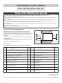
READ BEFORE INSTALLING UNIT
For Through-the-Wall Air Conditioners
1
Installation Instructions
NOTE: DO NOT USE ANY SCREWS OTHER THAN THOSE SPECIFIED HERE
Do This First (for existing sleeve)
You may not need all parts in the kit. Discard unused parts.
Items in Kit
16120300A29375
INSTALLATION WARNINGS AND CAUTION
Carefully read the installation manual before beginning. Follow each step as shown.
Observe all local, state, and national electrical codes and by qualified, licensed, authorized personnel only.
Pay attention to danger and safety notices.
To avoid risk of personal injury, property damage, or product damage due to the weight of this device and sharp edges that
may be exposed.
Air conditioners covered in this manual pose an excessive weight hazard. Two or more people are needed to move and
install the unit. Wear protective gloves whenever lifting or carrying the unit. AVOID the sharp metal fins of front and rear coils.
To prevent injury or strain, use proper lifting and carrying techniques when moving unit.
Carefully inspect location where air conditioner will be installed. Be sure it will support the weight of the unit over an extended
period of time.
Handle air conditioner with care.
Make sure air conditioner does not fall during installation.
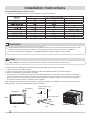
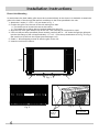
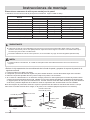
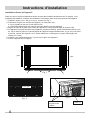
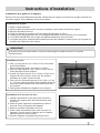
20" min
(510 mm)
20" min
(510 mm)
6.3" min (160 mm)
Outdoor sideIndoor side
Note that the air conditioner dimensions are: 24" wide,14"
high, and 19" deep (without front). Install air conditioner
according to these installation instructions to achieve the best
performance. Save these installation instructions for future
reference.
There should be enough
The appliance with electric heater shall have at least 1 meter
space to the combustible materials.
clearance around the unit as shown
in the right figure.

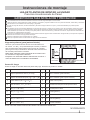
Common Wall-Sleeve Dimensions
IMPORTANT
All wall sleeves used to mount the new air conditioner must be in sound structural condition and have a rear
grille that securely attached to the sleeve, or rear flange that serves as a stop for the air conditioner.
For new or replacement installations, a Frigidaire Sleeve Kit (5304514430) is recommended.
1. Identify the wall-sleeve brand for your installation, from the chart below.
• Remove old air conditioner from wall sleeve and prepare wall sleeve as follows:
1. Clean interior (do not disturb seals)
2. Check to see that sleeve is securely fastened in wall. Add additional screws or nails as required.
3. Retouch wall sleeve painted surface if needed.
4. If a ground wire or mounting hole does not exist, drill a pilot hole for a grounding screw through the left hand
Note: Wall sleeve must be securely fastened in wall before installing Air Conditioner. Drive more nails or screws
through sleeve, into wall, if needed(Repair paint if needed).
side of the sleeve. Drill in a clear area about 3 inches back from the front edge a 3/16” pilot hole for the ground
screw. Pull the loose end of the ground wire out of the front of the sleeve and bend it away from the opening.
This will be attached to the air conditioner once installed.
NOTE:
When installation is complete, replacement unit must have rearward slope as shown in Fig 1.
1/4” to 5/16”
Wall Sleeve
Front
Rear
1.giF
Level
2.giF
Sleeve
3/16” Pilot Hole
Wall sleeve to unit
Grounding.
3”
Max
1”
GE/Hotpoint/Amana
Friedrich (USC)
Fedders/Emerson/Friedrich (WSE)*
For larger sleeves, an adaptor trim kit (EA120T) is available.
16”, 17 ½”, or 22”
16”, 17 ½”, or 22”
16”, 17 ½”, or 22”
16 ”
78
17 ” or 23”
18
18 ”
58
18 ”
58
16 ”
34
25 ”
78
15 ”
12
16 ”
78
16 ”
78
15 ”
58
25 ”
78
2
Installation Instructions
Indoor part Outdoor part

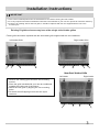
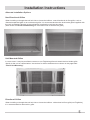
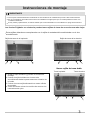
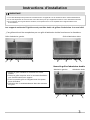
Existing Frigidaire sleeves may have older single sided intake grilles
New Dual Intake Grille
IMPORTANT
This units increased performance characteristics is the result of having two rear intakes.
If there is an existing sleeve and rear grille, it should be replaced with the one shipped with the unit in the
accessory kit.
It is very important that these installation instructions are followed so your unit can operate at maximum efficiency.
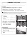
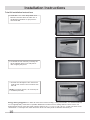
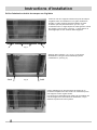
1. Remove the existing grille and save the mounting
screws.
2. Place the grille included with your new air conditioner
towards the inside rear of the sleeve.
3. Attach the new grille by aligning the four mounting
holes.
4. Re-insert the self-tapping screws into the nylon
retainers.
• These grilles should be replaced with the dual intake grille supplied with the air conditioner.
Left Intake Grille
Left Intake
Right Intake Grille
Right Intake
3
Installation Instructions

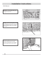
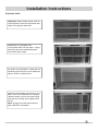
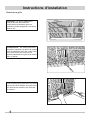
Grille Removal
Important: Single intake grilles must be
removed when used with dual intake
Through-the-wall Units.
Warning: When removing grilles, protect
from falling by securing with a leash. This
can be fashioned from cord or strapping
looped through the grille and secured
with a knot.
Holding the grille by the leash with one
hand the retaining screws can be
removed and the grille can be brought
inside through the front of the sleeve.
4
Installation Instructions

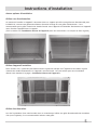
Alternate Installation Options
Non-Directional Grilles
Unit Mounted Grilles
When installing a through-the-wall unit into a sleeve that utilizes a non-directional air flow grille, such as
diamond expanded grille or an archiectural grille. It is recommended that the dual intake grillet supplied with
the unit, be attached directly to the unit before inserting the unit into the sleeve.
(See section on Direct Unit Mounting for instructions how to attache the grille)
In some cases it may be possible to remove a non-Frigidaire grille and attach the dual intake grille
directly to the unit as shown below. Instructions for direct attachment are shown on the page titled
“Direct Unit Mounting”
5
Installation Instructions
Directional Grilles
When installing a through-the-wall unit into a sleeve that utilizes a directional air flow grille( not Frigidaire),
It is recommended to remove this grille.

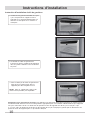
Direct Unit Mounting
In cases where the dual intake grille cannot be mounted directly to the sleeve it is desirable to attach the
grille to the back of the through-the-wall air conditioner to the holes predrilled in the unit.
1. Attach the 2 seals (1” x 3/8” x 14”) as shown in Fig. 1.
2. Position the grille over the rear of the unit making sure that:
a. The double set of screw holes are at the bottom
b. The intake fins on either side are pointed away from the unit.
3. Align the top of the grille with the top of the unit. The overhang on each side is equal.
4. If the unit has not been predrilled (some models), carefully drill 4 – 1/8” holes through the grille and
into the side flange of the unit approximately 1 ½” to 2 “ from the top and bottom as in Fig. 2 & Fig. 3.
(Be careful not to drill into the copper heat exchanger coil)
5. Install 4 - #8 self-tapping screws to affix the grille to the unit.
6. Insert the unit into the sleeve.
Grille Screws
Location
Fig. 2
1/8 Hole
Grille &
Flange
# 8 Screw
Fig. 3
Fig. 1
seal seal
6
Installation Instructions

Grille to Sleeve Attachment
In cases where the dual intake grille fits inside the sleeve and the grille flange overlaps the sleeve flange,
direct attachment may be possible.
Grille Installation
1. Remove the existing grille.
2. Place the grille included with the new air conditioner towards the rear of the sleeve.
3. Mark through the hole positions.
4. Drill through the sleeve flanges with a 1/8" drill bit.
5. Attach the new grille with self-threading screws and washers (not included).
6. It is VERY IMPORTANT that the grille is placed exactly as shown.
7. Most decorative exterior grilles may be left in place as long as the proper interior air direction
grille is installed.
Ground Wire Installation
1. Install screw end of ground wire into inside of sleeve
according to preparation instructions.
2. Before sliding unit all the way back remove second
screw from left side of unit.
3. Remove plastic washer from screw.
4. Screw the other end of the ground wire into the unit as
shown. Make sure the toothed washer is against the
cabinet.
5. Slide unit completely to the rear.
If the provided grille is not used, it may lead to product damage and possible failure.
IMPORTANT
7
Installation Instructions
Seal Installation
1. Attach(1)1" x 1 ½" x 25" long seal in the center at the
top of the sleeve.
Remove the backing paper and press into position.
2. Attach(2)1" x 1 ½" x 14" seals to the left and right sides
of the sleeve.
3. Cut(2)1" x 3/8" x 25" long seals to 14" long each and
attach to the vertical sections of the grille as shown.
Use these next steps if the unit requires extra
extension into the room.
4. Attach (2) 4½" x 3½" x 1½" foam blocks with the slot
overlapping the seal above.
5. Install the divider into the slots of the foam blocks. You
may need to trim the length to size.
6. Repeat steps 4-5 for the other vertical shown portion
of the grille as shown in the picture.
7. Gently slide unit into sleeve.
5
4

Non-Frigidaire Dual Intake Grille
In cases where the existing sleeve is a non-Frigidaire
sleeve but is installed with a dual intake grille. The existing
grille may be left in place. Make sure the outer 3 ½” to 4 ½”
louvers are angled from the left and right sides of the
sleeve toward the center. (See Fig. 1). This provides
proper flow of outside air into the unit.
From the installation kit, apply two 1” x ¾” x 14” seals along
the flat metal flange of the condenser. (See Fig. 2).
Insert the unit with the seals into the sleeve pushing it all the
way to rear making sure the seal are against the rear grille.
The seals are necessary to reduce recirculation of hot
exhaust air into the intakes which would reduce system
performance.
Fig. 1
Fig. 2
8
Installation Instructions

Subsitute Grille
Important: Single intake grilles must be
removed when used with used with dual
intake Through-the-wall Units.
Installation of a standard size
Through-the-Wall unit into older – larger
sleeves may leave undesirable gaps
around the grille edges.
An option is to purchase ¾” diamond cut
aluminum grille and cut it to fit inside the
sleeve. Secure it with screws.
Attach the dual intake grill directly to the
back of the unit as described on page 6.
Slide the entire unit into the sleeve and
seal with the stuffing seal supplied with
the kit.
Note: A larger front trim kit accessory
part # EA120T is available.
9
Installation Instructions

10
Trim Kit Installation Instructions
1. Install the 1” x 1” x 84” long stuffer seal
between the wall sleeve and the unit. A
flat-bladed screwdriver or putty knife is
recommended.
2. Assemble the trim frame by inserting the
top and bottom pieces into side pieces
and snapping into place.
Energy Saving Suggestion: In order to reach the maximum energy saving and comfort, it is recommended to
use an appropriately sized cover to provide additional insulation and air sealing when the unit is not in use
during the off-season. The size of the unit front panel is 24.2” x 14.6” x 2” (W x H x D), so the size of the cover
should be 0.3”~0.5”larger than each dimension of the unit front panel to facilitate satisfactory fit.
3. Pull the cord through the trim frame and
slide the trim over the unit until flush with
the wall.
NOTE: For larger sleeves, an accessory kit
is available (EA120T)
Installation Instructions

1
Instrucciones de montaje
LEA ESTO ANTES DE MONTAR LA UNIDAD
Para Aire Acondicionado de Pared
NOTA: NO USE TORNILLOS QUE NO SEAN LOS ESPECIFICADOS ACA.
Haga esto primero (para junta existente)
Puede no llegar a necesitar todas las partes del juego. Deseche las partes no usadas.
Items del Juego
Ferreteria
2
2
3
Bloques espaciadores cónicos (17” Long)
Divisor Plástico (1/8” )
4
Sello de relleno ( )
4
1
2
3
4
5sello ( )
1
62
37
8
.tnaC.oN
2
9
Bloques de Centrado/Soporte ( ” )
4 ” x 3 ” x 1
121212
x 4 ” x 14 ”
1212
1” x 1 ” x 84”
12
1” x 1 ” x 25”
12
sello ( )
1” x 1 ” x 14”
12
sello ( )
1” x 3/8” x 25”
sello ( )
1” x 3/8” x 14”
sello ( )
1” x 3/4” x 14”2
Ferreteria
2
1
1
Cable a tierra (verde)
2
13
10
11
12
14 Tornillo puesta a tierra
151
161
17
.tnaC.oN
4
18
Marco moldeado (pata superior & inferior)
Parrilla (plástico)
Parrilla Aluminio
Tuercas (plástico)
Tornillo c/arandela 4
Marco moldeado (patas laterales)
Arandela dentada para tornillo puesta a tierra 2
Lea cuidadosamente el manual de instalación antes de comenzar. Siga cada paso como se indica.
IADVERTENCIAS PARA INSTALACION Y
PRECAUCIÓN
Para evitar el riesgo de lesiones, de daños materiales y de daños al equipo debido a su peso y a los bordes afilados que puedan quedar
expuestos:
Los aparatos de aire acondicionado detallados en este manual suponen un peligro por su excesivo peso. Es necesaria la intervención de dos
o más personas para mover e instalar el equipo. Utilice guantes protectores cuando necesite levantarlo o moverlo. EVITE tocar las afiladas
aletas metálicas que existen en el frontal y en la parte posterior. Para evitar lesiones y problemas musculares, emplee técnicas adecuadas de
levantamiento y desplazamiento del mismo.
Preste atención a las notificaciones sobre peligro y seguridad.
Inspeccione cuidadosamente la localización donde piensa instalar el equipo de aire acondicionado. Asegúrese de que es capaz de soportar el
peso del mismo durante un largo periodo de tiempo.
Manipule el aparato de aire acondicionado con cuidado.
Evite que el aparato de aire acondicionado se caiga durante la instalación.
Observe todos los códigos eléctricos locales, estatales y nacionales y haga la instalación solo con personal calificado, matriculado y autorizado.
16120300A29375
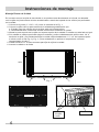
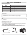
20" min
(510 mm)
20" min
(510 mm)
6.3" min (160 mm)
Lado exteriorLado interior
Observe que las dimensiones del aire acondicionado son:
24" ancho, 14" alto y 19" profundidad (sin el frente). Instale el
Aire acondicionado según estas instrucciones de montado
para lograr el mayor rendimiento. Guarde estas instrucciones
de montado para futuras consultas.
Debe haber suficiente espacio alrededor de la unidad como
se muestra en la figura de la derecha.
El aparato con calentador eléctrico deberá tener al menos 1
metro de distancia a los materiales combustibles.

2
Instrucciones de montaje
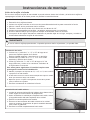
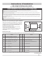
Dimensiones comunes de nicho para montaje en la pared
IMPORTANTE
Todas las fundas de pared utilizadas para montar el nuevo aire acondicionado deben estar en una sólida
situación estructural y tener una rejilla posterior sujeta de manera segura a la funda o una brida trasera que
sirva de tope para el aire acondicionado.
Para las instalaciones nuevas o de reposición, se recomienda un juego de funda Frigidaire (5304514430).
1. Identificar la marca de la funda de pared para su instalación, según la tabla de abajo.
*Para fundas mayores, se dispone de un juego de ajuste adaptador (EA120T).
Retirar el viejo aparato de aire acondicionado de la funda de pared y preparar el soporte de pared de la
siguiente manera:
1. Limpiar el interior (no alterar los sellos)
2. Comprobar que la funda esté bien sujeta a la pared. Añadir tornillos o clavos adicionales según sea necesario.
3. Retocar la superficie pintada del nicho para montaje en la pared, si es necesario.
4. Si no existe un cable de tierra o un orificio de montaje, perforar un orificio piloto para un tornillo de puesta a tierra
a través de la parte izquierda de la funda. Taladrar en una zona abierta alrededor de 3 pulgadas del borde frontal
un agujero piloto de 3/16” para el tornillo de tierra. Tirar del extremo suelto del cable de tierra por la parte delantera
de la funda y doblarlo alejándolo de la abertura. Esto se adjuntará al aire acondicionado una vez instalado.
NOTA:
Cuando finalice la instalación, la unidad de reemplazo estar inclinada hacia atrás como se muestra en la
Figura 1.
1/4” a 5/16”
Funda de pared
etnaleDDetrás
Fig. 1
A nivel
Puesta a tierra de
la funda de pared
Fig. 2
Funda
Orificio piloto
de 3/16”
3”
Máx
1”
Dimensiones de la funda de pared
Marca
Frigidaire
White-Westinghouse
Carrier (52 Series)
GE/Hotpoint/Amana
Whirlpool
Fedders/Emerson/Friedrich (WSE)*
Sears/Kenmore
Emerson/Fedders
Carrier (51S Series)
Friedrich (USC)
Altura
15 14”
15 14”
15 14”
15 58”
16 12”
16 34”
16 78”
15 34”
16 78”
15 12”
Ancho
25 12”
25 12”
25 12”
26”
25 78”
27”
25 34”
26 34”
25 34”
25 78”
Profundidad
16”, 17 12” o 22”
16”, 17 12” o 22”
16”, 17 12” o 22”
16 78”
17 18” o 23”
16 34” o 19 34”
18 58”
15”
18 58”
16 34”
Nota: El manguito de pared debe estar bien sujeto a la pared antes de instalar el acondicionador de aire. Coloque
más clavos o tornillos a través de la manga, en la pared, si es necesario (Repare la pintura si es necesario).
Parte interior Parte exterior

3
Instrucciones de montaje
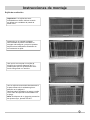
Las fundas Frigidaire en existencia pueden tener rejillas de toma de una sola cara más viejas
Nueva rejilla de toma doble
1. Quitar la rejilla existente y guardar los tornillos de
montaje.
2. Colocar la rejilla incluida con el nuevo aire
acondicionado hacia la parte trasera en el interior de
la funda.
3. Colocar la nueva rejilla alineando los cuatro orificios
de montaje.
4. Volver a insertar colocar los tornillos de rosca en los
retenedores de nylon.
Rejilla de toma de la izquierda
Toma izquierda
Rejilla de toma de la derecha
Toma derecha
Estas rejillas deberán ser reemplazadas con la rejilla de entrada doble suministrada con el aire
acondicionado.
Las mejores características de rendimiento de esta unidad es el resultado de que tiene dos tomas traseras.
Si hay funda y rejilla trasera, se deben sustituir por los suministrados con la unidad en el juego de accesorios.
Es muy importante que estas instrucciones de instalación se sigan para que su unidad pueda funcionar con
la máxima eficiencia.
IMPORTANTE

Remoción de la rejilla
Importante: Las rejillas de toma
individuales se deben eliminar cuando se
utilizan con unidades de pared de doble
toma.
Advertencia: Al retirar las rejillas,
asegurar la protección contra caídas con
una atadura. Esto se puede hacer con
una cuerda o por correas enrolladas por
la rejilla y aseguradas con un nudo.
Sosteniendo la rejilla por la atadura con
una mano se pueden quitar los tornillos
de sujeción y la rejilla se puede llevar
adentro a través de la parte frontal de
la funda.
4
Instrucciones de montaje

Opciones de instalación alternativas
Rejillas no direccionales
Instalación de una unidad a través de la pared en una funda que utiliza una rejilla de flujo de aire no
direccional, tal como rejilla de diamante expandida o una rejilla arquitectónica Se recomienda que la rejilla
de entrada doble suministrada con la unidad, se conecte directamente a la unidad antes de insertar la
unidad en el soporte.
(Ver la sección sobre Montaje Directo de la Unidad para instrucciones de cómo unir la rejilla)
Rejillas montadas en la unidad
En algunos casos, puede ser posible quitar una rejilla que no sea de Frigidaire y adjuntar la rejilla doble
directamente a la unidad como se muestra a continuación. Las instrucciones para el montaje directo se
muestran en la página titulada "Montaje Directo de Unidad"
5
Instrucciones de montaje
Rejillas direccionales
Al instalar la unidad a través de la pared en una funda que utiliza la rejillaa de flujo de aire direccional (no
Frigidaire), Se recomienda quitar esta rejilla.

6
Instrucciones de montaje
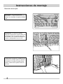
Montaje Directo de Unidad
En los casos en que la rejilla de toma doble no se puede montar directamente a la funda, es deseable
unir la rejilla a la parte trasera del aire acondicionado a través de la pared de los orificios pre-perforados
en la unidad.
1. Colocar las 2 juntas (1” x 3/8” x 14”) como se muestra en la Fig. 1.
2. Colocar la rejilla sobre la parte trasera de la unidad asegurándose de que:
a. El doble juego de orificios de los tornillos estén en la parte inferior.
b. Las aletas de toma a cada lado señalan en dirección contraria a la unidad.
3. Alinear la parte superior de la rejilla con la parte superior de la unidad. El voladizo en cada lado es igual.
4. Si la unidad no está pre-perforada (algunos modelos), perfore cuidadosamente orificios de 4 1/8” a
través de la rejilla y en la brida lateral de la unidad a aproximadamente 1 ½” a 2” de la parte superior
e inferior como en las Fig. 2 y Fig. 3. (Tener cuidado de no perforar el serpentín de cobre del
intercambiador de calor)
5. Instalar tornillos # 4 - 8 autorroscantes para fijar la rejilla a la unidad.
6. Insertar la unidad en la funda.
Ubicación de los
tornillos de la rejilla
Fig. 2
Orificio de
1/8 rejilla
y brida
Tornillo # 8
Fig. 3
Fig. 1
sello sello

7
Instrucciones de montaje
Unión de la rejilla a la funda
En los casos en que la rejilla de toma doble se pueda colocar dentro de la funda y la brida de la rejilla se
superponga a la brida de la funda, puede ser posible la conexión directa.
Si no se utiliza la rejilla proporcionada, se pueden provocar daños al producto y su posible fallo.
IMPORTANTE
Instalación de la rejilla
1. Remoción de la rejilla existente.
2. Colocar las rejillas incluidas en el nuevo aire acondicionado hacia la parte trasera de la funda.
3. Marcar a través de las posiciones de los orificios.
4. Taladrar a través de las bridas de la funda con una broca de 1/8”.
5. Colocar la nueva parrilla con tornillos y arandelas autorroscantes (no incluidos).
6. Es MUY IMPORTANTE que la rejilla se coloque exactamente como se muestra.
7. La mayoría de las rejillas decorativas exteriores se pueden dejar en su lugar, siempre y cuando se
instale adecuadamente la rejilla de aire interior.
Instalación del cable a tierra
1. Instalar el extremo del tornillo del cable a tierra dentro de la
funda según las instrucciones de preparación.
2. Antes de deslizar la unidad por completo hacia atrás, retirar
el segundo tornillo del lado izquierdo de la unidad.
3. Retirar la arandela plástica del tornillo.
4. Enroscar el otro extremo del cable a tierra en la unidad
como se muestra. Asegurarse de que la arandela dentada
está contra el gabinete.
5. Deslizar la unidad completamente hacia atrás.
Instalación del sello
1. Colocar un (1) sello de 1" x 1 ½" x 25" de largo en el
centro en la parte superior de la funda.
Retirar el papel protector y presionar en su posición.
2. Colocar dos (2) sellos de 1" x 1 ½" x 14" a los lados
izquierdo y derecho de la funda.
3. Cortar (2) sellos de 1" x 3/8" x 25" de largo a 14" de
largo cada uno y unirlos a las secciones verticales de
la rejilla como se muestra.
Use estos pasos siguientes si la unidad requiere una
prolongación extra hacia la habitación.
4. Adhiera (2) bloques de espuma de 4½" x 3½" x 1½" con la ranura
superpuesta al sello anterior.
5. Instale el divisor en las ranuras de los bloques de espuma. Puede
tener que recortar el largo a la medida.
6. Repita los pasos 4-5 para la otra porción vertical de la parrilla,
como se indica en el gráfico.
7. Deslizar suavemente la unidad en la funda.
5
4

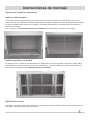
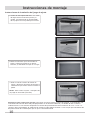
Rejilla de toma doble no Frigidaire
En los casos en que la funda existente es una funda no
Frigidaire, pero está instalada con una rejilla de doble
toma. La rejilla existente se puede dejar en su lugar.
Asegurarse de que las persianas exteriores de 3 ½” a
4 ½” están en ángulo con los lados izquierdo y derecho
de la funda hacia el centro. (Ver la Fig. 1). Esto permite
un flujo apropiado de aire del exterior a la unidad.
Del juego de instalación, aplicar dos sellos de 1” x ¾” x 14”
a lo largo de la brida plana de metal del condensador.
(Ver la Fig. 2).
Insertar la unidad con los sellos en la funda empujando todo
lo posible hacia atrás y asegurándose que los sellos quedan
junto a la rejilla.
Los sellos son necesarios para reducir la recirculación del
aire de escape caliente en las tomas, lo que reduciría el
buen funcionamiento del sistema.
Fig. 1
Fig. 2
Sello Sello
8
Instrucciones de montaje

9
Instrucciones de montaje
Rejilla de sustitución
Importante: Las rejillas de toma
individuales se deben eliminar cuando
se utilizan con unidades de pared de
doble toma.
Instalación de un tamaño estándar
Las unidades de pared colocadas en
mangas más antiguas y mayores pueden
dejar brechas indeseables alrededor de
los bordes de la rejilla.
Una opción es comprar una rejilla de
aluminio de corte de diamante de ¾” y
cortarla para que se ajuste dentro de la
funda. Asegurarla con tornillos.
Unir la rejilla de toma doble directamente a
la parte trasera de la unidad según se
describe en la página 6.
Deslizar toda la unidad en la manga y sellar
con el sello de taponear suministrado con
el juego.
Nota: Se dispone de un juego de accesorios
de ajuste mayor, pieza # EA120T.

10
Instrucciones de instalación del juego de ajuste
1. Instalar el sello taponeador de 1” x 1” x 84”
de largo entre la funda de la pared y la
unidad. Se recomienda un destornillador
de hoja plana o una espátula para masilla.
2. Monte el marco de ajuste insertando las
piezas superior e inferior en las piezas
laterales y haciéndolas encajar en su lugar.
3. Halar la cuerda a través del marco de
ajuste y deslizar el ajuste por encima de la
unidad hasta que esté al mismo nivel de la
pared.
NOTA: Para fundas mayores, se dispone de
un juego de accesorios (EA120T)
Instrucciones de montaje
Sugerencia para el ahorro de energía: Para lograr el máximo confort y ahorro de energía, se recomienda usar
una cubierta de tamaño adecuado para proporcionar un aislamiento adicional y el sellado del aire cuando la
unidad no está en uso fuera de temporada. El tamaño del panel delantero de la unidad es de 24.2” x 14.6” x 2”
(ancho x alto x profundidad), de modo que el tamaño a cubrir deberá ser de 0.3“~0.5” mayor que cada dimensión
del panel frontal de la unidad para que se ajuste satisfactoriamente.
La page est en cours de chargement...
La page est en cours de chargement...
La page est en cours de chargement...
La page est en cours de chargement...
La page est en cours de chargement...
La page est en cours de chargement...
La page est en cours de chargement...
La page est en cours de chargement...
La page est en cours de chargement...
La page est en cours de chargement...
La page est en cours de chargement...
La page est en cours de chargement...
-
 1
1
-
 2
2
-
 3
3
-
 4
4
-
 5
5
-
 6
6
-
 7
7
-
 8
8
-
 9
9
-
 10
10
-
 11
11
-
 12
12
-
 13
13
-
 14
14
-
 15
15
-
 16
16
-
 17
17
-
 18
18
-
 19
19
-
 20
20
-
 21
21
-
 22
22
-
 23
23
-
 24
24
-
 25
25
-
 26
26
-
 27
27
-
 28
28
-
 29
29
-
 30
30
-
 31
31
-
 32
32


Frigidaire FHTE143WA2 Manuel utilisateur
- Taper
- Manuel utilisateur
dans d''autres langues
- English: Frigidaire FHTE143WA2 User manual
- español: Frigidaire FHTE143WA2 Manual de usuario