
Write the model and serial
numbers here:
Model # _________________
Serial # _________________
You can find the this information
on a label attached to the right
side of the chassis.
GE is a trademark of the General Electric Company. Manufactured under trademark license.
AIR CONDITIONER
24” Through-the-Wall
49-5000444 Rev. 0 01-20 GEA
ESPAÑOL
For a Spanish version of this
manual, visit our Website at
www.GEAppliances.com.
Para consultar una version
en español de este manual
de instrucciones, visite nuestro
sitio de internet
www.GEAppliances.com.
FRANÇAIS
For a French version of this
manual, visit our Website at
www.GEAppliances.ca.
Pour un version français de
ce manuel d’utilisation, veuillez
visiter notre site web à l’adresse
www.GEAppliances.ca.
SAFETY INFORMATION .........3
USING THE AIR
CONDITIONER ..............4
CARE AND CLEANING ...........7
INSTALLATION
INSTRUCTIONS ...............8
TROUBLESHOOTING TIPS ......17
CONSUMER SUPPORT
Warranty ............................19
Consumer Support ................... 20
OWNER’S MANUAL &
INSTALLATION
INSTRUCTIONS
Cool Only Models
AKCQ08A
AKCQ10A
AKCQ10D
AKCQ12A
AKCQ12D
AKCQ14D
Heat/Cool Models
AKEQ10D
AKEQ12D
AKEQ14D

2 49-5000444 Rev. 0
THANK YOU FOR MAKING GE APPLIANCES A PART OF YOUR HOME.
Whether you grew up with GE Appliances, or this is your first, we’re happy to have you in the family.
We take pride in the craftsmanship, innovation and design that goes into every GE Appliances
product, and we think you will too. Among other things, registration of your appliance ensures that we
can deliver important product information and warranty details when you need them.
Register your GE appliance now online. Helpful websites and phone numbers are available in the
Consumer Support section of this Owner’s Manual. You may also mail in the pre-printed registration
card included in the packing material.

49-5000444 Rev. 0 3
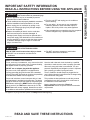
SAFETY INFORMATION
IMPORTANT SAFETY INFORMATION
READ ALL INSTRUCTIONS BEFORE USING THE APPLIANCE
For your safety, the information in this manual must be followed to minimize the risk of
fire, electric shock or personal injury.
■ Use this appliance only for its intended purpose as
described in this Owner’s Manual.
■ This air conditioner must be properly installed in accordance
with the Installation Instructions before it is used.
■ Never unplug your air conditioner by pulling on the
power cord. Always grip plug firmly and pull straight
out from the receptacle.
■ Replace immediately all electric service cords that
have become frayed or otherwise damaged. A
damaged power supply cord must be replaced with a
new power supply cord obtained from the manufacturer
and not repaired. Do not use a cord that shows cracks
or abrasion damage along its length or at either the
plug or connector end.
■ Turn the unit OFF and unplug your air conditioner
before cleaning.
■ For your safety…do not store or use combustible
materials, gasoline or other flammable vapors or
liquids in the vicinity of this or any other appliance.
■ If the receptacle does not match the plug, the receptacle
must be changed out by a qualified electrician.
USE OF EXTENSION CORDS
RISK OF FIRE. Could cause serious injury or death.
■ DO NOT use an extension cord with this air
conditioner.
■ DO NOT use surge protectors or multi-outlet
adaptors with this air conditioner.
HOW TO CONNECT ELECTRICITY
Do not, under any circumstances, cut or remove the third
(ground) prong from the power cord. For personal safety,
this appliance must be properly grounded.
DO NOT use an adapter plug with this appliance.
The power cord of this appliance is equipped with a
3-prong (grounding) plug which mates with a standard
3-prong (grounding) wall outlet to minimize the possibility
of electric shock hazard from this appliance.
Power cord includes a current interrupter device. A test
and reset button is provided on the plug case. The device
should be tested on a periodic basis by first pressing the
TEST button and then the RESET button while plugged
into the outlet. If the TEST button does not trip or if the
RESET button will not stay engaged, discontinue use of the
air conditioner and contact a qualified service technician.
Have the wall outlet and circuit checked by a qualified
electrician to make sure the outlet is properly grounded.
Where a 2-prong wall outlet is encountered, it is your
personal responsibility and obligation to have it replaced
with a properly grounded 3-prong wall outlet.
The air conditioner should always be plugged into its
own individual electrical outlet which has a voltage rating
that matches the rating plate.
This provides the best performance and also prevents
overloading house wiring circuits which could cause a
fire hazard from overheated wires.
See the Installation Instructions, Electrical
Requirements section for specific electrical connection
requirements.
WARNING
READ AND SAVE THESE INSTRUCTIONS
For appliance recycling information please visit GEAppliances.com/recycling.
WARNING

4 49-5000444 Rev. 0
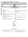
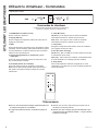
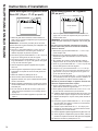
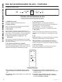
Air Conditioner Controls
■ To ensure proper operation, aim the remote control at
the signal receiver on the air conditioner.
■ The remote control signal has a range up to 21 feet.
■ Make sure nothing is between the air conditioner and
the remote control that could block the signal.
■ Make sure the battery is fresh and installed correctly—
see the Care and Cleaning section.
Appearance may vary.
Remote Control
Lights above the touch pads on the air conditioner
control panel indicate the selected settings.
Using the Air Conditioner - Controls
USING THE AIR CONDITIONER
1. POWER
Turns air conditioner on and off.
2. Display
Displays the temperature setting. Displays hours when
setting the timer.
3. Mode
Use to set COOL, HEAT (on some models), DRY, AUTO,
or FAN modes. Indicator lights on the controls will show
the mode selected.
4. Temp Increase + / Decrease - Pads
Use to set temperature when in Auto, Cool, Dry or Heat
(on some models) mode.
5. Fan Speed
Use to set the fan speed at LOW, MEDIUM, or HIGH.
Indicator lights will show the speed selected.
6. Timer
ON - Use to set the air conditioner to automatically turn ON
from .5 to 24 hours later.
OFF - Use to automatically turn the air conditioner OFF
from .5 to 24 hours later.
7. Filter
Monitors accumulated fan run time as a reminder to clean
the filter.
8. Eco
ON: Use to cycle the fan off when the compressor cycles
off.
OFF: Use to run the fan continuously when in cooling or
heating (on some models) mode.
9. Sleep
Allows room temperature to increase (Cool mode) or
decrease (Heat mode) during sleeping hours.
Temp/Timer

49-5000444 Rev. 0 5
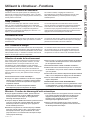
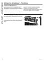
Using the Air Conditioner - Features
USING THE AIR CONDITIONER
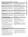
To Adjust Fan Speeds
Press the Fan Speed button to select the FAN Speed
in four steps - Auto, Low, Med, or High. Each time the
button is pressed, the fan speed mode is shifted.
For some models, the fan speed can not be adjusted
under HEAT mode. In DRY mode, the fan speed is
controlled at low automatically.
Sleep
Press the Sleep button to initiate the sleep mode. In this
mode the selected temperature will increase (cooling)
or decrease (heating) by 2°F / 1°C 30 minutes after the
mode is selected. The temperature will then increase
(cooling) or decrease (heating) by another 2°F / 1°C after
an additional 30 minutes.
This new temperature will be maintained for 7 hours
before it returns to the originally selected temperature.
This ends the Sleep mode and the unit will continue
to operate as originally programmed. The Sleep mode
program can be cancelled at any time during operation
by pressing the Sleep button again.
Check Filter
Press the Filter button to initiate this feature. This feature
is a reminder to clean the air filter for more efficient
operation.
The LED (light) will illuminate after 250 hours of
operation. To reset after cleaning the filter, press the Filter
button and the light will go off.
Eco - Energy Saver
Press the Eco button to initiate this feature. This feature
is available on COOL, DRY, AUTO, (only AUTO-COOLING
and AUTO-FAN) modes. The fan will continue to run for 3
minutes after the compressor shuts off.
The fan then cycles on for 2 minutes at 10 minute
intervals until the room temperature is above the set
temperature, at which time the compressor turns back on
and Cooling starts.
Timer: Auto Start / Stop
■
When the unit is on or off, first press the Timer button,
the TIMER ON indicator light illuminates. It indicates the
Auto Start program is initiated.
■ When the time of TIMER ON is displayed, press the
Timer button again, the TIMER OFF indicator light
illuminates. It indicates the Auto Stop program is initiated.
■
Press or hold the UP or DOWN button to change the
Auto time by 0.5 hour increments, up to 10 hours, then
at 1 hour increments up to 24 hours. The control will
count down the time remaining until start.
■
The selected time will register in 5 seconds, and the
system will automatically revert back to display the
previous temperature setting or room temperature when
the unit is on. (When the unit is off, there is no display.)
■
Turning the unit ON or OFF at any time or adjusting the
timer setting to 0.0 will cancel the Auto Start/Stop timed
program.
To Select the Operating Mode
To choose operating mode, press the Mode button.
Each time you press the button, a mode is selected in a
sequence that goes from Auto, Cool, Dry, Heat (on some
models) and Fan only. The indicator light above will be
illuminated and remain on once the mode is selected.
The unit will initiate the Energy Saver function under
Cool, Dry, Auto (only Auto-Cooling and Auto-Fan) modes.
To Operate on Auto Feature:
■
When you set the air conditioner in AUTO mode, it will
automatically select cooling, heating (on some models)
or fan only operation depending on what temperature
you have selected and the room temperature.
■
The air conditioner will control room temperature
automatically to the temperature set point.
■ In this mode, the fan speed cannot be adjusted, it starts
automatically at a speed according to the room temperature.
To Operate on Fan Only:
■ Use this function only when cooling is not desired. You
can choose any fan speed you prefer.
■ During this function, the display will show the actual
room temperature, not the set temperature in the
cooling mode.
■ In Fan only mode, the temperature is not adjustable.
To Operate on Dry Mode:
■ In this mode, the air conditioner will generally operate in
the form of a dehumidifier. Since the conditioned space
is a closed or sealed area, some degree of cooling will
continue.

6 49-5000444 Rev. 0
Using the Air Conditioner - Features
USING THE AIR CONDITIONER
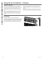
Additional Features
The “Cool” circuit has an automatic 3 minute delayed
start if the unit is turned off and on quickly. This prevents
overheating of the compressor and possible circuit
breaker tripping. The fan will continue to run during this
time.
There is a 2 second delay for the compressor to stop
when selecting FAN ONLY/HEAT. This is to cover the
possibility of having to roll through to select another
mode.
The control will maintain the set temperature within 1°F
between 62°F and 86°F in cool or heat mode (on some
models).
After a power outage, the unit will remember last setting
and return the unit to that setting when power is restore.
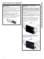
Air Direction
Air directional louvers control air flow direction.
The louvers will allow you to direct the air flow up or down
and left or right throughout the room as needed until the
desired left/right direction is obtained. Pivot horizontal
louvers until the desired up/down direction is obtained.

49-5000444 Rev. 0 7
CARE AND CLEANING
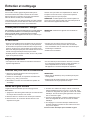
Care and Cleaning
How to Insert the Batteries in the Remote Control
1. Remove the battery cover by rotating it to the unlock
position.
2. Insert a new battery, making sure that the (+) and (-) of
the battery are installed correctly, (+) side up.
3. Reattach the cover by rotating it back into the lock
position.
NOTES:
• Use 1 CR2025 (3 VDC) battery. Do not use rechargeable
batteries.
• Remove the battery from the remote control if the
system is not going to be used for an extended period
of time.
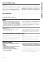
Outdoor Coils
• The coils on the outdoor side of the air conditioner
should be checked regularly.
• If they are clogged with dirt or soot, they may need to
be professionally cleaned, a service available through
GE Appliances service or other service companies.
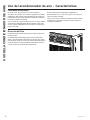
Front Grille Removal
The front grille can be removed for a more thorough
cleaning.
To remove:
1. Grasp the sides of the front grille by the recessed
areas on each side and tilt forward.
2. Remove the filter by pulling forward and out.
3. Remove the two Phillips head screws located on the
upper corners of the grille.
4. Push inward on each side of the metal chassis cover
about 5” from the bottom. This will release the tabs on
the grille from the metal chassis cover. Pull the bottom
of the grille slightly forward while lifting the grille
upward.
5. Once the grille is released, gently raise it upward to
release the tabs from the top of the metal chassis cover.
6. To release the multi-pin electrical connector from the
user interface, press both sides and gently pull apart.
Reverse the order to re-install the grille.
Air filter
To access the filter, grasp the front grille on both sides at
the recess and tilt forward. Remove the filter by lifting up
and out. Note the filter direction when re-installing.
Wash the filter using liquid dishwashing detergent and
warm water. Rinse the filter thoroughly. Gently shake
excess water from the filter.
Be sure the filter is thoroughly dry before replacing. Or,
instead of washing, you may vacuum the filter until clean.
NOTE: Never use hot water over 104°F (40°C) to clean
the air filter. Never attempt to operate the unit without the
air filter.
Energy Saving Note
In order to reach maximum energy saving and comfort, it
is recommended to use a cover to insulate the unit when
the unit is not in use. The recommended cover size for
the unit is 24.4” x 14.8” x 2.2” (W x H x D).
NOTE: Unplug the unit before installing a cover.
Cabinet
• Be sure to unplug the air conditioner to prevent shock
or fire hazard. The cabinet and front may be dusted
with an oil-free cloth or washed with a cloth dampened
in a solution of warm water and mild liquid dishwashing
detergent. Rinse thoroughly with a damp cloth and wipe
dry.
•
Never use harsh cleaners, wax, or polish on the cabinet front.
• Be sure to wring excess water from the cloth before
wiping around the controls. Excess water in or around
the controls may cause damage to the air conditioner.
• Plug in the air conditioner.

8 49-5000444 Rev. 0
INSTALLATION INSTRUCTIONS
Installation Instructions
For more help, visit GEAppliances.com
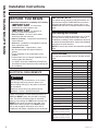
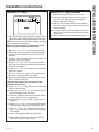
BEFORE YOU BEGIN
Read these instructions completely and carefully.
•
IMPORTANT – Save these
instructions for local inspector’s use.
•
IMPORTANT – Observe all
governing codes and ordinances.
• Note to Installer – Be sure to leave these
instructions with the consumer.
• Note to Consumer – Keep these instructions for
future reference.
• Skill level – Installation of this appliance requires
basic mechanical skills.
• Completion time – Approximately 1 hour
• We recommend that two people install this
product.
• Proper installation is the responsibility of the
installer.
• Product failure due to improper installation is not
covered under the Warranty.
• You MUST use proper installation procedures as
described in these instructions when installing this
air conditioner.
Power cord includes a current interrupter device. A
TEST and RESET button are provided on the plug
case. The device should be tested on a periodic
basis by first pressing the TEST button and then the
RESET button while plugged into the outlet. If the
TEST button does not trip or if the RESET button
will not stay engaged, discontinue use of the air
conditioner and contact a qualified service technician.
ELECTRICAL REQUIREMENTS
Do not, under any circumstances, cut or remove
the third (ground) prong from the power cord.
Do not change the plug on the power cord of this
air conditioner.
Aluminum house wiring may present special
problems—consult a qualified electrician.
For Existing Wall Sleeves
Note that the air conditioner dimensions are: 24” wide,
14” high, and 18” deep (without front). Install air
conditioner according to these Installation Instructions
to achieve the best performance. Save these Installation
Instructions for future reference.
NOTE: Do not use any screws other than those specified
here.
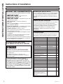
Parts Included
You may not need all parts in the kit. Discard unused
parts.
Name Spec. Qty
Tapered spacer Blocks 17” long 2
Centering/Support Blocks 4-1/2” x 3-1/2” x 1-1/2” 4
Plastic Divider 1/8” x 4-1/2” x 14-1/2” 2
Stuffer Seal 1” x 1-1/2” x 25” 1
Seal 1” x 1-1/2” x 14” 3
Seal 1” x 3/8” x 25” 2
Seal 1” x 3/8” x 14” 3
Seal 1” x 3/4” x 14” 2
Seal 2
Trim Frame (side legs) 2
Trim Frame (top & bottom legs) 2
Ground Wire (green) 1
Toothed Washer for grounding
screw
2
Grounding Screw 1
Grille (Plastic) 1
Grille (Aluminum) 1
Nuts (Plastic) 4
Screw Washer 4
Screw 4
Security Brackets for a 24” Wall
Sleeve (in a separate packet
with their 4 mounting screws)
2
Security Brackets for a 26” Wall
Sleeve (in a separate packet
with their 4 mounting screws)
2
IMPORTANT NOTE
For optimal energy efficiency and performance, we
recommend using the RAB24 Wall Sleeve and the
supplied stamped aluminum outdoor grille or the
RAB46B with the RAG13 stamped aluminum outdoor
grille.
CAUTION

49-5000444 Rev. 0 9
Installation Instructions
INSTALLATION INSTRUCTIONS
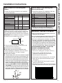
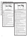
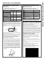
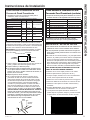
How to Install In Pre-Existing Wall
Sleeve
1. Identify the wall-sleeve brand for your installation,
from the chart below.
Wall Sleeve Dimensions (inches)
Width Height Depth
White-Westinghouse
25-1/2 15-1/4 16, 17-1/2 or 22
Frigidaire
Carrier (52F Series)
GE/Hotpoint 26 15-5/8 15-7/8
Whirlpool 25-7/8 16-1/2 17-1/8 or 23
Fedders/Emerson 27 16-3/4 16-3/4 or 19-3/4
Sears/Kenmore
25-3/4 16-7/8 18-5/8
Carrier (51S Series)
Emerson/Fedders 26-3/4 15-3/4 15
Friedrich 27 16-3/4 16-3/4
NOTE: All wall sleeves used to mount the new air
conditioner must be in sound structural condition and
have a rear grille that securely attaches to sleeve, or
rear flange that serves as a stop for the air conditioner.
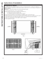
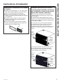
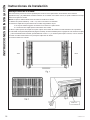
IMPORTANT: When installation is complete, replacement
unit MUST have a rearward slope as shown.
2. Remove old air conditioner from wall sleeve and
prepare wall sleeve as follows:
■ Clean interior (do not disturb seals).
■
Wall sleeve must be securely fastened in wall
before installing air conditioner. Drive more nails or
screws through sleeve, into wall, if needed.
■ Repair paint if needed.
3.
If not pre-existing, drill a 1/8” hole to attach the supplied
grounding wire to the left side of the wall sleeve (see
approximate hole location dimensions in the illustration
below). Use the toothed washer and pointed screw to
attach one end of the supplied green striped ground
wire to the inside of the wall sleeve. The toothed
washer must be between the eyelet of the wire and the
wall sleeve. BE CAREFUL TO NOT OVERTIGHTEN
THE SCREW. Pull loose end of ground wire out front
of sleeve, and temporarily bend it down and around
lower edge of sleeve. This ground wire will later be
attached to frame of air conditioner once it is installed.
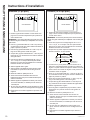
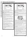
How to Install In Pre-Existing Wall
Sleeve (continued)
4. Prepare the wall sleeve for installation of the new
unit per the following brand instructions.
1 Emerson 15” Deep
2 Fedders 19-3/4” Deep
3 Fedders or Friedrich 16-3/4” Deep
4 GE/Hotpoint 16-7/8” Deep
5 Sears or Carrier (51S Series) 18-5/8” Deep
6 Whirlpool 17-1/8” Deep
7 Whirlpool 23” Deep
8 White-Westinghouse/
Frigidaire/Carrier (52F Series)
16” + 17-1/2” Deep
9 White-Westinghouse/Frigidaire 22” Deep
5. Identify your wall sleeve type and follow the
instructions for that type in the following pages.
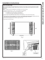
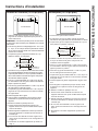
IMPORTANT - BEFORE YOU BEGIN
■ This unit’s performance characteristics result from
having two rear air intakes.
■ It is very important that these instructions are followed
so the unit can operate at maximum efficiency.
■ If this is an existing sleeve and there is an existing
rear grille, it may need to be replaced by one that has
been shipped with the unit in the accessory kit. If the
new rear grille is too small for the rear sleeve opening,
use the black plastic grille. Insure it is secured in place
using the included screws, washers and grommets.
FOR INCREASED EFFICIENCY, UTILIZE THE
PROVIDED LOUVERED REAR PANEL
Installation of new grille provided with unit.
1. Remove the existing grille. (Exception: GE 26”.)
2. Place the grille, included with the new air
conditioner, towards the rear of the sleeve.
3. Mark through the hole positions.
4. Drill through the sleeves flanges with a 1/8” drill bit.
5. Attach the new grille with self-threading screws
and washers.
6. It is VERY IMPORTANT that the grille is placed
exactly as shown below.
7. Most decorative exterior grilles may be left in place as
long as the proper interior air direction grille is installed.
REAR
Wall Sleeve
UNIT
LEVEL
FRONT
to
ARRIÈRE
Compartiment mural
APPAREIL
NIVEAU
AVANT
1/4 po à 3/16 po
PARTE
TRASERA
Forro para pared
UNIDAD
NIVEL
PARTE
FRONTAL
a
3
3
1
3
Max.
1/8
Hole

10 49-5000444 Rev. 0
INSTALLATION INSTRUCTIONS
Installation Instructions
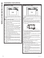
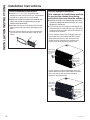
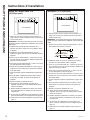
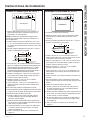
Emerson (15” Deep)
4
4
3
8
3
8
1. Remove existing rear grille as shown on page 9 of
this manual and replace with provided louvered rear
panel.
NOTE: You may need to drill holes in flange of existing
sleeve to match new rear grille.
2. Attach (1) 1” x 3/8” x 25” long seal in the center at
the top of the sleeve. Remove the backing paper
and press into position.
3. Attach the (2) 1” x 3/8” x 14” long seals to the left
and right sides of the sleeve.
4. Cut (2) 1” x 3/8” x 25” seals to 14” long and attach
them to the vertical sections of the rear grille.
5. Attach (2) 4-1/2” x 3-1/2” x 1-1/2” centering/support
blocks, one on each side wall. Place in center of
side wall with the tapered end facing the opening.
6. Gently slide unit into sleeve.
7. Before sliding all-the-way back, remove the second
screw from front on the left side of unit.
8. Remove the plastic washer from the screw.
9. Screw and attach the other end of the ground wire
to the unit. Make sure that the toothed washer is
against the cabinet.
10. Slide the unit completely to the rear to ensure a
good seal, making sure the ground wire does not
become tangled.
11. If you have difficulty with mounting the grill to the
sleeve, follow the instructions for direct mounting on
page 15.
12. Seal and frame the unit as described on page 16.
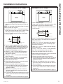
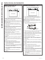
Fedders (19-3/4” Deep)
4
4
3
8
3
8
1. Remove existing rear grille as shown on page 9 of
this manual and replace with provided louvered rear
panel.
NOTE: You may need to drill holes in flange of existing
sleeve to match new rear grille.
2 Attach (2) 4-1/2” x 3-1/2” x 1-1/2” centering/support
blocks, one on each side wall. Place in center of
side wall with the tapered end facing the opening.
3. Cut (2) 17” tapered spacer blocks as shown below
into two pieces.
Cut Here
3
/
4
17
Tapered Spacer Block
1
Protection Paper
Backing
4
4. The 4” section is placed in front of the rib on base
with the tapered end facing the back of the sleeve.
The remaining portion will be placed behind the rib
again sloping toward
the rear of the sleeve. This helps induce a rearward
slope on the unit.
5. Attach (1) 1” x 3/8” x 25” long seal in the center at
the top of the sleeve. Remove the backing paper
and press into position.
6. Attach (2) 1” x 3/8” x 14” seals to the left and right
sides of the sleeve.
7. Cut (2) 1” x 3/8” x 25” seals to 14” long and attach
them to the vertical sections of the rear grille.
8. Gently slide unit into sleeve.
9. Before sliding all-the-way back, remove the second
screw from front on left side of unit.
10. Remove the plastic washer from the screw.
11. Screw and attach the other end of the ground wire
to the unit. Make sure that the toothed washer is
against the cabinet.
12. Slide the unit completely to the rear to ensure a
good seal, making sure the ground wire does not
become tangled.
13. If you have difficulty with mounting the grill to the
sleeve, follow the instructions for direct mounting
on page 15.
14. Seal and frame the unit as described on page 16.

49-5000444 Rev. 0 11
Installation Instructions
INSTALLATION INSTRUCTIONS
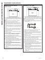
Fedders or Friedrich (16-3/4” Deep)
1. Remove existing rear grille as shown on page 9 of
this manual and replace with provided louvered rear
panel.
NOTE: You may need to drill holes in flange of existing
sleeve to match new rear grille.
2. Attach (2) 4-1/2” x 3-1/2” x 1-1/2” centering/support
blocks, one on each side wall. Place in center of side
wall with the tapered end facing the opening.
3. Cut (2) 17” tapered spacer blocks as shown below
into three pieces.
Cut Here
3
/
4
17
Tapered Spacer Block
1
Protection Paper
Backing
12-1/2
2-1/2
4. The 2-1/2” section is placed in front of the rib on base
with the tapered end facing the back of the sleeve. Cut
the remaining portion to 12-1/2” and placed behind the
rib again sloping toward the rear of the sleeve. This
helps induce a rearward slope on the unit.
5. Attach (1) 1” x 3/8” x 25” long seal in the center at
the top of the sleeve. Remove the backing paper
and press into position.
6. Attach (2) 1” x 3/8” x 14” seals to the left and right
sides of the sleeve.
7. Cut (2) 1” x 3/8” x 25” seals to 14” long and attach
them to the vertical sections of the rear grille.
8. Gently slide unit into sleeve.
9. Before sliding all-the-way back, remove the second
screw from front on left side of unit.
10. Remove the plastic washer from the screw.
11. Screw and attach the other end of the ground wire
to the unit. Make sure that the toothed washer is
against the cabinet.
12. Slide the unit completely to the rear to ensure a
good seal, making sure the ground wire does not
become tangled.
13. If you have difficulty with mounting the grill to the
sleeve, follow the instructions for direct mounting
on page 15.
14. Seal and frame the unit as described on page 16.
GE/Hotpoint (16-7/8” Deep)
4
4
3
8
3
8
1. Retain existing rear grille.
2. Using needle nose pliers, change the outdoor grille
directional louvers per the illustration above.
3. Cut (2) 17” tapered spacer blocks as shown below
into two pieces.
4. Install 13” section with the tapered end 1/2” from the
back of the sleeve. This helps induce a rearward
slope on the unit.
5. Attach (1) 1” x 3/8” x 25” long seal in the center at
the top of the sleeve. Remove the backing paper
and press into position.
6. Attach (2) 1” x 3/8” x 14” seals to the left and right
sides of the sleeve.
7. Cut (2) 1” x 3/8” x 25” seals to 14” long and attach
them to the vertical sections of the rear grille.
8. Center unit and gently slide unit into sleeve.
9. Before sliding all-the-way back, remove the second
screw from front on left side of unit.
10. Remove the plastic washer from the screw.
11. Screw and attach the other end of the ground wire
to the unit. Make sure that the toothed washer is
against the cabinet.
12. Slide the unit completely to the rear to ensure a
good seal, making sure the ground wire does not
become tangled.
13. If you have difficulty with mounting the grill to the
sleeve, follow the instructions for direct mounting
on page 15.
14. Seal and frame the unit as described on page 16.
4
4
3
8
3
8
3
/
4
17
Tapered Spacer Block
1
Protection Paper
Backing
Cut Here
13

12 49-5000444 Rev. 0
INSTALLATION INSTRUCTIONS
Installation Instructions
Sears or Carrier 51S Series
(18-5/8” Deep)
4
4
3
8
3
8
1. Remove existing rear grille as shown on page 9 of
this manual and replace with provided louvered rear
panel.
NOTE: You may need to drill holes in flange of
existing sleeve to match new rear grille.
2. Install (2) tapered spacer blocks to the floor of the
sleeve. This helps induce a rearward slope on the
unit.
3. Install with the tapered end 1/2” from the back of the
sleeve. This helps induce a rearward slope on the
unit.
4. Attach (1) 1” x 3/8” x 25” long seal in the center at
the top of the sleeve. Remove the backing paper
and press into position.
5. Attach (2) 1” x 3/8” x 14” seals to the left and right
sides of the sleeve.
6. Cut (2) 1” x 3/8” x 25” seals to 14” long and attach
them to the vertical sections of the rear grille.
7. Center unit and gently slide unit into sleeve.
8. Before sliding all-the-way back, remove the second
screw from front on left side of unit.
9. Remove the plastic washer from the screw.
10. Screw and attach the other end of the ground wire
to the unit. Make sure that the toothed washer is
against the cabinet.
11. Slide the unit completely to the rear to ensure a
good seal, making sure the ground wire does not
become tangled.
12. If you have difficulty with mounting the grill to the
sleeve, follow the instructions for direct mounting on
page 15.
13. Seal and frame the unit as described on page 16.
Whirlpool (17-1/8” Deep)
4
4
3
8
3
8
1. Remove existing rear grille as shown on page 9 of this
manual and replace with provided louvered rear panel.
NOTE: You may need to drill holes in flange of existing
sleeve to match new rear grille.
2. Cut (2) 17” tapered spacer blocks as shown below
into two pieces.
3
/
4
17
Tapered Spacer Block
1
Protection Paper
Backing
Cut Here
13
3. Install 13” section to the floor of the sleeve. This
helps induce a rearward slope on the unit.
4. Attach (1) 1” x 3/8” x 25” long seal in the center at
the top of the sleeve. Remove the backing paper
and press into position.
5. Attach (2) 1” x 3/8” x 14” seals to the left and right
sides of the sleeve.
6. Cut (2) 1” x 3/8” x 25” seals to 14” long and attach
them to the vertical sections of the rear grille.
7. Center unit and gently slide unit into sleeve.
8. Before sliding all-the-way back, remove the second
screw from front on left side of unit.
9. Remove the plastic washer from the screw.
10. Screw and attach the other end of the ground wire
to the unit. Make sure that the toothed washer is
against the cabinet.
11. Slide the unit completely to the rear to ensure a
good seal, making sure the ground wire does not
become tangled.
12. If you have difficulty with mounting the grill to the
sleeve, follow the instructions for direct mounting
on page 15.
13. Seal and frame the unit as described on page 16.

49-5000444 Rev. 0 13
Installation Instructions
INSTALLATION INSTRUCTIONS
Whirlpool (23” Deep)
4
4
3
8
3
8
1. Remove existing rear grille as shown on page 9 of this
manual and replace with provided louvered rear panel.
NOTE: You may need to drill holes in flange of existing
sleeve to match new rear grille.
Because of the increased unit depth, first try dry
fitting using the method described below:
2. Place (2) 1” x 1-1/2” x 14” seals against each side.
3. Gently slide unit in and check if amount extending
from the sleeve is sufficient once the trim frame is
attached.
4. If position is correct, remove unit and proceed to the
next step. If not, go to step 9.
5. Attach (1) 1” x 1-1/2” x 25” long seal in the center
at the top of the sleeve. Remove the backing paper
and press into position.
6. Attach (2) 1” x 1-1/2” x 14” seals to the left and right
sides of the sleeve.
7. Cut (2) 1” x 3/8” x 25” seals to 14” long and attach
them to the vertical sections of the grille.
8. Attach the tapered spacer blocks to the floor of the
sleeve. Now go to step 15.
Use these next steps if the unit requires extra
extension into the room:
9. Attach 1” x 3/4” x 14” long seal over the solid vertical
portion of the rear grille.
10. Attach (4) 4-1/2” x 3-1/2” x 1-1/2” foam blocks with
the slot overlapping the seal above.
11. Install the divider into the slots of the foam blocks.
You may need to trim the length to size.
12. Repeat steps 9-11 for the other vertical portion of
the grille.
13. Attach (2) 1” x 1-1/2” x 14” seals along the sides of
the sleeve again making sure all seals are flush.
14. Cut the 1” x 1-1/2” x 25” seal to fit the top of the
sleeve. The pieces must be fitted flush to the edge
of the divider.
15. Center unit and gently slide unit into sleeve.
16. Before sliding all-the-way back, remove the first
screw from front on left side of unit.
Whirlpool (23” Deep) continued
17. Remove the plastic washer from the screw.
18. Screw and attach the other end of the ground
wire to the unit. Make sure that the toothed
washer is against the cabinet.
19. Slide the unit completely to the rear to ensure a
good seal, making sure the ground wire does not
become tangled.
20. If you have difficulty with mounting the grill to the
sleeve, follow the instructions for direct mounting
on page 15.
21. Seal and frame the unit as described on page 16.

14 49-5000444 Rev. 0
INSTALLATION INSTRUCTIONS
Installation Instructions
White-Westinghouse/Frigidaire/Carrier
52F Series (16” + 17-1/2” Deep)
4
4
3
8
3
8
1. Remove existing rear grille as shown on page 9 of
this manual and replace with provided louvered rear
panel.
NOTE: You may need to drill holes in flange of
existing sleeve to match new rear grille.
2. Attach (1) 1” x 3/8” x 25” long seal in the center at
the top of the sleeve. Remove the backing paper
and press into position.
3. Attach (2) 1” x 3/8” x 14” seals to the left and right
sides of the sleeve.
4. Attach (2) 1” x 3/4” x 14” long seals vertically 4.5”
from the left side of the sleeve and 4” from the
right side of the sleeve.
5. Center unit and gently slide unit into sleeve.
6. Before sliding all-the-way back, remove the
second screw from front on left side of unit.
7. Remove the plastic washer from the screw.
8. Screw and attach the other end of the ground
wire to the unit. Make sure that the toothed
washer is against the cabinet.
9. Slide the unit completely to the rear to ensure
a good seal, making sure the ground wire does
not become tangled.
10. If you have difficulty with mounting the grill to the
sleeve, follow the instructions for direct mounting
on page 15.
11. Seal and frame the unit as described on page 16.
White-Westinghouse or Frigidaire
(22” Deep)
1. Remove existing rear grille as shown on page 9 of this
manual and replace with provided louvered rear panel.
NOTE: You may need to drill holes in flange of existing
sleeve to match new rear grille.
Because of the increased unit depth, first try dry
fitting using the method described below:
2. Place (2) 1” x 1-1/2” x 14” seals against each side.
3. Gently slide unit in and check if amount extending from
the sleeve is sufficient once the trim frame is attached.
4. If position is correct, remove unit and proceed to the
next step. If not, go to step 8.
5. Attach (1) 1” x 1-1/2” x 15” long seal to the left side
and right side of the sleeve.
6. Cut (1) 1” x 1-1/2” x 25” seal to 14” long and attach
them vertically to the rear grill 4.5” from the left side of
the sleeve and 4” from the right side of the sleeve.
7. Attach (1) 1” x 1-1/2” x 25” long seal in the center at
the top of the sleeve. Remove the backing paper and
press into position. Proceed to step 14.
Use these next steps if the unit requires extra
extension into the room.
8. Attach 1” x 3/4” x 14” long seal over the solid vertical
portion of the rear grille.
9. Attach (4) 4-1/2” x 3-1/2” x 1-1/2” foam blocks with the
slot overlapping the seal above.
10. Install the divider into the slots of the foam blocks.
You may need to trim the length to size.
11. Repeat steps 8-10 for the other vertical shown
portion of the grille.
12. Attach (2) 1” x 1-1/2” x 14” seals along the sides of
the sleeve again making sure all seals are flush.
13. Cut the 1” x 1-1/2” x 25” seal to fit the top of the
sleeve. The pieces must be fitted flush to the edge of
the divider.
14. Center unit and gently slide unit into sleeve.
15. Before sliding all-the-way back, remove the first
screw from the front on left side of the unit.
16. Remove the plastic washer from the screw.
17. Screw and attach the other end of the ground wire
to the unit. Make sure that the toothed washer is
against the cabinet.
18. Slide the unit completely to the rear to ensure a good seal,
making sure the ground wire does not become tangled.
19. If you have difficulty with mounting the grill to the
sleeve, follow the instructions for direct mounting
on page 15.
20. Seal and frame the unit as described on page 16.
4
4
3
8
3
8

49-5000444 Rev. 0 15
INSTALLATION INSTRUCTIONS
Installation Instructions
Direct Unit Mounting:
The previous directions are the preferable way to mount the new rear grille. The units performance is slightly
better and the possibility of drafts is reduced. As a last resort, direct mounting of the grille to the unit can be
considered.
NOTE: The grille must be installed prior to inserting the unit into the sleeve.
1. Attach the 2 seal pieces (1” x 3/8” x 14”) as shown in the illustration.
2. Position the grille over the rear of the unit making sure that:
a. The double set of screw holes are at the bottom.
b. The fins of the grille are pointed away from the unit.
3. Align the top of the grille with the top of the unit. The overhang on each side should be equal.
4. If the unit has not been pre-drilled (some models), carefully drill (4) 1/8” holes through the grille and into the
side flange of the unit approximately 1-1/2” to 2” from the top and bottom as shown.
5. Install 4 #8 self-tapping screws to affix the grille to the unit.
6. Insert the unit into the sleeve.

16 49-5000444 Rev. 0
Installation Instructions
INSTALLATION INSTRUCTIONS
Trim Kit Installation Instructions
■
Install the 1” x 1-1/2” x 84” long stuffer seal
between the wall sleeve and the unit. A flat-bladed
screwdriver or putty knife is recommended.
■ Measure the height and width of the installed wall
sleeve and choose the appropriate trim kit that
matches those dimensions.
■
Assemble the trim frame by inserting the top and
bottom pieces into side pieces and snapping into
place.
■
Pull the cord through the trim frame and slide the
trim over the unit until flush with the wall or wall
sleeve.
Assemble Trim
Ensamblar moldura
Assembler la garniture
Security Brackets Installation
(It is important to install these brackets
to prevent the chassis from being
pushed into the room from the outside.)
■ Measure the width of the installed wall sleeve and
choose the appropriate security bracket (24” or 26”)
designed for that sleeve.
■
The brackets must be installed so the flanges are
hooked behind the inside flanges of the wall sleeve.
Using the screws provided, attach the brackets on
the sides of the chassis.
For 24” sleeves, pull the unit out slightly, hook the
short flange of the 24” bracket behind the sleeve
inside edge and secure to the unit with the two
screws provided. Repeat on the opposite side.
Push the unit all the way back into the case.
For 26” sleeves, hook the short flange of the 26”
bracket behind the sleeve inside edge and secure
to the unit with the the two screws provided.
Repeat on the opposite side.
Hook inside
sleeve edge
and secure
to unit
Hook inside
sleeve edge
and secure
to unit
Hook inside
sleeve edge
and secure
to unit
Hook inside
sleeve edge
and secure
to unit

49-5000444 Rev. 0 17
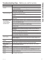
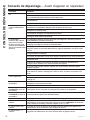
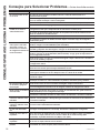
Troubleshooting Tips... Before you call for service
TROUBLESHOOTING TIPS
Problem Solution
Air conditioner does
not start
Wall plug disconnected. Push plug firmly into wall outlet.
House fuse blown or circuit breaker tripped. Replace fuse with time delay type
or reset circuit breaker.
Plug current device tripped. Press the RESET button.
Power is OFF. Turn power ON.
Air from the unit does
not feel cold enough
Room temperature below 62°F (17°C). Cooling may not occur until room
temperature rises above 62°F (17°C).
Temperature sensor behind air filter may be touching cold coil. Keep it from the
cold coil.
Set to a lower temperature.
Compressor stopped when changing modes. Wait for 3 minutes after set to the
COOL mode.
Air conditioner cooling,
but room is too warm.
Ice is forming on
cooling coil behind
decorative front.
Outdoor temperature below 64°F (18°C). To defrost the coil, set FAN ONLY mode.
Air filter may be dirty. Clean the filter. Refer to Care and Cleaning section. To
defrost, set to FAN ONLY mode.
Thermostat set to cold for night-time cooling. To defrost the coil, set to FAN
ONLY mode. Then, set temperature to a higher setting.
Dirty air filter, or the air is restricted. Clean the air filter. Refer to Care and
Cleaning section.
Temperature is set too high. Set the temperature to a lower setting.
Air directional louvers positioned improperly. Position louvers for better air
distribution.
Front of unit is blocked by drapes, blinds, furniture, etc, which restricts air
distribution. Clear blockage in front of unit.
Doors, windows, registers, etc, may be open. Close doors, windows, registers.
Unit recently turned on in hot room. Allow additional time to remove “stored
heat” from walls, ceiling, floor, and furniture.
Air conditioner turns on
and off rapidly
Dirty air filter, the air is restricted. Clean air filter.
Outside temperature extremely hot. Set FAN speed to a higher setting to cool
outdoor cooling coil.
Noise when unit is
cooling
Air movement sound. This is normal. If too loud, set to a slower FAN setting.
Improper installation. Refer to installation instructions or check with installer.
Water dripping INSIDE
when unit is cooling
Improper installation. Tilt air conditioner slightly to the outside to allow water
drainage. Refer to installation instructions, and check with installer.
Water dripping
OUTSIDE when unit is
cooling
Unit removing large quantity of moisture from humid room. This is normal
during excessively humid days.
Room too cold Set temperature to low. Increase set temperature.
Error code “AS” in the
display
Room temperature sensor error. Unplug the unit and plug it back in. If error
repeats, call for service. NOTE: In Fan only mode, it will display “LO” or “HI”.
Error code “HS” in the
display
Electric heating sensor error. Unplug the unit and plug it back in. If error
repeats, call for service.
Error code “
•
” in the
display
Evaporator temperature sensor error. Unplug the unit and plug it back in. If
error repeats, call for service.

18 49-5000444 Rev. 0
Notes
NOTES

49-5000444 Rev. 0 19
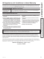
GE Appliances Air Conditioner Limited Warranty
Staple your receipt here. Proof of the original purchase date
is needed to obtain service under the warranty.
LIMITED WARRANTY
■ Service trips to your home to teach you how to use
the product.
■ Improper installation, delivery or maintenance. If you
have an installation problem, or if the air conditioner
is of improper cooling capacity for the intended use,
contact your dealer or installer. You are responsible
for providing adequate electrical connecting facilities.
■ Failure of the product resulting from modifications
to the product or due to unreasonable use including
failure to provide reasonable and necessary
maintenance.
■ In commercial locations, labor necessary to move the
unit to a location where it is accessible for service by
an individual technician.
■ Replacement of house fuses or resetting of circuit
breakers.
■ Failure due to corrosion on models not corrosion-
protected.
■ Damage to the product caused by improper power
supply voltage, accident, fire, floods or acts of God.
■ Incidental or consequential damage caused by
possible defects with this air conditioner.
■ Damage caused after delivery.
What GE Appliances Will Not Cover:
This limited warranty is extended to the original purchaser and any succeeding owner for products purchased
for home use within the USA. If the product is located in an area where service by a GE Appliances Authorized
Servicer is not available, you may be responsible for a trip charge or you may be required to bring the product to an
Authorized GE Service location for service. In Alaska, the limited warranty excludes the cost of shipping or service
calls to your home.
Some states do not allow the exclusion or limitation of incidental or consequential damages. This limited warranty
gives you specific legal rights, and you may also have other rights which vary from state to state. To know what your
legal rights are, consult your local or state consumer affairs office or your state’s Attorney General.
Warrantor: GE Appliances, a Haier company
Louisville, KY 40225
All warranty service must be provided by our Factory Service Centers, or an authorized Customer Care
®
technician.
To schedule service, visit us on-line at GEAppliances.com/service, or call 800.GE.CARES (800.432.2737). Have
serial number and model number available when calling for service.
EXCLUSION OF IMPLIED WARRANTIES—Your sole and exclusive remedy is product repair as provided in this
Limited Warranty. Any implied warranties, including the implied warranties of merchantability or fitness for a
particular purpose, are limited to two years or the shortest period allowed by law.
For The Period Of: GE Appliances Will Replace:
Two Years
From the date of the
original purchase
Any part of the air conditioner which fails due to a defect in materials or workmanship.
During this limited two-year warranty, GE Appliances will also provide, free of charge, all
labor and related service to replace the defective part.

20 49-5000444 Rev. 0
Printed in China
Consumer Support
GE Appliances Website
Have a question or need assistance with your appliance? Try the GE Appliances Website 24 hours a day, any day
of the year! You can also shop for more great GE Appliances products and take advantage of all our on-line support
services designed for your convenience. In the US: GEAppliances.com
Register Your Appliance
Register your new appliance on-line at your convenience! Timely product registration will allow for enhanced
communication and prompt service under the terms of your warranty, should the need arise. You may also mail in
the pre-printed registration card included in the packing material. In the US: GEAppliances.com/register
Schedule Service
Expert GE Appliances repair service is only one step away from your door. Get on-line and schedule your service at
your convenience any day of the year. In the US: GEAppliances.com/service or call 800.432.2737 during normal
business hours.
Extended Warranties
Purchase a GE Appliances extended warranty and learn about special discounts that are available while your
warranty is still in effect. You can purchase it on-line anytime. GE Appliances Services will still be there after your
warranty expires. In the US: GEAppliances.com/extended-warranty or call 800.626.2224 during normal
business hours.
CONSUMER SUPPORT
Parts and Accessories
Individuals qualified to service their own appliances can have parts or accessories sent directly to their homes
(VISA, MasterCard and Discover cards are accepted). Order on-line today 24 hours every day.
In the US: GEApplianceparts.com or by phone at 877.959.8688 during normal business hours.
Instructions contained in this manual cover procedures to be performed by any user. Other servicing
generally should be referred to qualified service personnel. Caution must be exercised, since improper
servicing may cause unsafe operation.
Contact Us
If you are not satisfied with the service you receive from GE Appliances, contact us on our Website with all the
details including your phone number, or write to:
In the US: General Manager, Customer Relations | GE Appliances, Appliance Park | Louisville, KY 40225
GEAppliances.com/contact
La page est en cours de chargement...
La page est en cours de chargement...
La page est en cours de chargement...
La page est en cours de chargement...
La page est en cours de chargement...
La page est en cours de chargement...
La page est en cours de chargement...
La page est en cours de chargement...
La page est en cours de chargement...
La page est en cours de chargement...
La page est en cours de chargement...
La page est en cours de chargement...
La page est en cours de chargement...
La page est en cours de chargement...
La page est en cours de chargement...
La page est en cours de chargement...
La page est en cours de chargement...
La page est en cours de chargement...
La page est en cours de chargement...
La page est en cours de chargement...
La page est en cours de chargement...
La page est en cours de chargement...
La page est en cours de chargement...
La page est en cours de chargement...
La page est en cours de chargement...
La page est en cours de chargement...
La page est en cours de chargement...
La page est en cours de chargement...
La page est en cours de chargement...
La page est en cours de chargement...
La page est en cours de chargement...
La page est en cours de chargement...
La page est en cours de chargement...
La page est en cours de chargement...
La page est en cours de chargement...
La page est en cours de chargement...
La page est en cours de chargement...
La page est en cours de chargement...
La page est en cours de chargement...
La page est en cours de chargement...
-
 1
1
-
 2
2
-
 3
3
-
 4
4
-
 5
5
-
 6
6
-
 7
7
-
 8
8
-
 9
9
-
 10
10
-
 11
11
-
 12
12
-
 13
13
-
 14
14
-
 15
15
-
 16
16
-
 17
17
-
 18
18
-
 19
19
-
 20
20
-
 21
21
-
 22
22
-
 23
23
-
 24
24
-
 25
25
-
 26
26
-
 27
27
-
 28
28
-
 29
29
-
 30
30
-
 31
31
-
 32
32
-
 33
33
-
 34
34
-
 35
35
-
 36
36
-
 37
37
-
 38
38
-
 39
39
-
 40
40
-
 41
41
-
 42
42
-
 43
43
-
 44
44
-
 45
45
-
 46
46
-
 47
47
-
 48
48
-
 49
49
-
 50
50
-
 51
51
-
 52
52
-
 53
53
-
 54
54
-
 55
55
-
 56
56
-
 57
57
-
 58
58
-
 59
59
-
 60
60


dans d''autres langues
- English: GE AKCQ14DCH Owner's manual
- español: GE AKCQ14DCH El manual del propietario
- português: GE AKCQ14DCH Manual do proprietário
Documents connexes
Autres documents
-
Maytag 23-11-2251N-004 Guide d'installation
-
Fedders A7U08W2B Le manuel du propriétaire
-
Haier HTWR08XCR Manuel utilisateur
-
Heat Controller Comfort-Aire BG-81A Le manuel du propriétaire
-
Haier HTWR10VCK Le manuel du propriétaire
-
Friedrich US12B10B Manuel utilisateur
-
-
-
-
Frigidaire All Air Conditioner Manuel utilisateur