HQ Power VARNA Manuel utilisateur
- Catégorie
- Stroboscopes
- Taper
- Manuel utilisateur
Ce manuel convient également à

VD
P
VARN
VARN
VARN
VARN
VARN
USER
M
GEBRU
MODE
MANU
A
BEDIE
N
P
500
1
A – RGB
5
A – RGB
5
A – PROJ
E
A – PROY
A – RGB
5
M
ANUAL
IKERSHAN
D
D’EMPLOI
A
L DEL USU
A
N
UNGSANLE
1
RGB
5
00MW L
A
5
00MW L
A
E
CTEUR L
A
ECTOR L
Á
5
00MW L
A
D
LEIDING
A
RIO
ITUNG
LD5
A
SER – D
M
A
SER – D
M
A
SER RVB
Á
SER RVA
5
A
SERPROJ
E
3
8
13
18
23
M
X CONTR
O
M
X-GESTU
U
500MW
–
5
00MW –
E
KTOR –
D
O
LLED
U
RD
–
PILOTA
G
CONTRO
L
D
MX-GES
T
G
E DMX
L
DMX
T
EUERT

VDP5001RGBLD5
V. 02 – 17/09/2012 2 ©Velleman nv
terminator – eindweerstand – résistance de
terminaison – terminación – Terminierung
How to turn the controller line from 3-pins into 5-pins (plug and socket).
Controller line van 3-pin naar 5-pin aanpassen (stekker en contact).
Modifier la ligne du contrôleur de 3 broches en 5 broches (fiche et contact).
Modificar la línea del controlador de 3 polos y 5 polos (conector y contacto).
Die Controller-Linie von 3-Pin nach 5-Pin anzupassen (Stecker und Kontakt).

V. 02 –
1
1.
I
To all r
e
Import
a
Thank y
o
service.
I
2.
S
•
This
quali
•
Mak
e
man
u
•
Do n
nece
•
Use
a
1
7/09/2012
I
ntroducti
o
e
sidents of th
e
a
nt environme
This symbol
o
could harm t
h
waste; it sho
u
returned to y
o
rules.
If in doubt,
c
o
u for choosing
I
f the device w
a
S
afety Inst
Be very
c
electros
h
Always
d
activitie
s
Indoor
u
liquids.
Keep thi
s
Caution
Use extr
e
When d
e
beam.
N
people’s
Do not p
There ar
e
service
a
device falls un
d
fied person car
r
e
sure that the
a
u
al.
ot crimp the po
ssary.
a
n appropriate
s
o
n
e
European Un
ntal informati
o
n the device or
h
e environment.
u
ld be taken to
a
o
ur distributor
o
c
ontact your l
o
HQPower™! Pl
e
a
s damaged in
t
ructions
c
areful during t
h
h
ocks.
d
isconnect main
s
are performed
u
se only. Kee
p
s
device away f
r
: device heats
u
e
me caution w
h
e
vice is in use,
d
N
EVER point th
e
or animals’ ey
e
oint the laser b
e
e
no use
r
-servi
c
a
nd/or spare pa
r
d
er protection cl
r
y out the elect
r
a
vailable voltag
wer cord and p
r
s
afety cable to
f
VDP5001
R
3
USER M
A
ion
on about this
the package in
Do not dispos
e
a
specialized c
o
o
r to a local rec
y
o
cal waste di
s
e
ase read the m
t
ransit, don't in
s
h
e installation:
s power when
d
. Handle the po
p
this device aw
a
r
om children a
n
u
p during use.
h
en the laser be
d
o NOT look d
i
e
laser beam di
r
e
s or skin. Burn
s
e
am towards hi
c
eable parts ins
r
ts.
ass I. It is ther
e
r
ic connection.
e does not exc
e
r
otect it agains
t
f
ix the device (
e
R
GBLD5
A
NUAL
product
dicates that dis
e
of the unit (o
r
o
mpany for rec
y
y
cling service.
R
s
posal authori
t
anual thorough
s
tall or use it a
n
touching live w
d
evice not in us
e
wer cord by th
e
a
y form rain, m
n
d unauthorized
am is turned o
n
i
rectly or indi
r
r
ectly or via a r
e
s
and permane
n
ghly explosive
g
ide the device.
e
fore essential
t
e
ed the voltage
t
damage. Hav
e
e
.g. VDLSC7N
o
posal of the de
v
r
batteries) as u
y
cling. This devi
c
R
espect the loc
a
t
ies.
ly before bringi
n
d contact your
ires can cause l
e
or when servi
e
plug only.
oisture, splashi
users.
n
.
r
ectly (reflecti
e
flecting surfac
e
n
t eye damage
w
g
asses.
Refer to an aut
t
hat the device
stated in the s
p
e
an authorised
o
r VDLSC8N).
©Velle
m
v
ice after its lif
e
nsorted munici
p
c
e should be
a
l environment
a
ng this device i
n
dealer.
ife-threatening
cing or mainte
n
ng and drippin
g
on) into the l
a
e
towards othe
r
w
ill result.
horized dealer
f
be earthed. Ha
v
p
ecifications of
t
dealer replace i
m
an nv
e
cycle
p
al
a
l
n
to
n
ance
g
a
ser
r
f
or
v
e a
t
his
t if

VDP5001RGBLD5
V. 02 – 17/09/2012 4 ©Velleman nv
• Install the VDP5001RGBLD5 at a minimal distance of 0.5 m from flammable and explosive objects or
substances.
• Respect a minimum distance of 0.5 m between the device’s light output and any illuminated surface.
• Keep the air vents free at all times. Never cover the device, nor partially, nor completely.
3. General Guidelines
Refer to the Velleman® Service and Quality Warranty on the last pages of this manual.
Keep this device away from dust and extreme temperatures. Make sure the ventilation
openings are clear at all times. For sufficient air circulation, leave at least 1" (±2.5 cm) in
front of the openings.
Protect this device from shocks and abuse. Avoid brute force when operating the device.
• Familiarise yourself with the functions of the device before actually using it. Do not allow operation
by unqualified people. Any damage that may occur will most probably be due to unprofessional use
of the device.
• All modifications of the device are forbidden for safety reasons. Damage caused by user modifications
to the device is not covered by the warranty.
• Only use the device for its intended purpose. All other uses may lead to short circuits, burns,
electroshocks, lamp explosion, crash, etc. Using the device in an unauthorised way will void the
warranty.
• Damage caused by disregard of certain guidelines in this manual is not covered by the warranty and
the dealer will not accept responsibility for any ensuing defects or problems.
• Mechanical wear is not covered by warranty.
• A qualified technician should install and service this device.
• Do not switch the device on immediately after it has been exposed to changes in temperature.
Protect the device against damage by leaving it switched off until it has reached room temperature.
• This device is designed for professional use on stage, in discos, theatres, etc. The VDP5001RGBLD5
should only be used indoors (<35°C, <75%RH) with an alternating current of 230 VAC/50 Hz.
• Lighting effects are not designed for permanent operation: regular operation breaks will prolong their
lives. It is recommended to let the device cool down for ± 15 minutes after every two hours of
operation.
• Use the original packaging if the device is to be transported.
• Keep this manual for future reference.
4. Features
• red-green-blue laser
• with circle, fan and line creating tunnel effects
• DMX controlled via 5 channels
• sound activation and auto control mode
• high capacity and speed micro processor
• low noise movement.
5. Overview
Refer to the illustrations on page 2 of this manual.
1 power LED 6 powe
r
cord input/fuse
2 built-in microphone 7 DMX input
3 sensitivity knob 8 DMX output
4 on/off switch 9 DIP switches
5 safety key (depending on model)

VDP5001RGBLD5
V. 02 – 17/09/2012 5 ©Velleman nv
6. Installation
Choose a suitable mounting spot. Mount the fixture in the desired angle using the included bracket.
Connect the power cord to the mains. Disconnect after use.
Mounting the Device
• Have the device installed by a qualified person, respecting EN 60598-2-17 and all other applicable
norms.
• The carrying construction must be able to support 10 times the weight of the device for 1 hour
without deforming.
• The installation must always be secured with a secondary attachment e.g. a safety cable.
• Never stand directly below the device when it is being mounted, removed or serviced. Have a
qualified technician check the device once a year and once before you bring it into service.
• Install the device in a location with few passers-by that is inaccessible to unauthorised persons.
• Overhead mounting requires extensive experience: calculating workload limits, determining the
installation material to be used… Have the material and the device itself checked regularly. Do not
attempt to install the device yourself if you lack these qualifications as improper installation may
result in injuries.
• For truss mounting, use an appropriate clamp (not incl.) and fit an M10 bolt through the centre of the
(folded) bracket.
• Adjust the desired inclination angle via the mounting bracket and tighten the bracket screws.
• Make sure there is no flammable material within a 0.5 m radius of the device.
• Have a qualified electrician carry out the electric connection.
• Connect the device to the mains with the power plug. Do not connect it to a dimming pack.
• The installation has to be approved by an expert before the device is taken into service.
DMX-512 Connection
• When applicable, connect an XLR cable to the female 3-pin XLR output of a controller (not incl.) and
the other side to the male 3-pin XLR input [7] of the VDP5001RGBLD5. Multiple VDP5001RGBLD5s
can be linked through serial linking. The linking cable should be a dual core, screened cable with XLR
input and output connectors.
• Maximum recommended serial data link distance is 500 meters (1640 ft). Maximum recommended
number of fixtures on a serial data link is 32 fixtures.
• A DMX terminator is recommended for installations where the DMX cable has to run a long distance
or is in an electrically noisy environment (e.g. discos). The terminator prevents corruption of the
digital control signal by electrical noise. The DMX terminator is simply an XLR plug with a 120Ω
resistor between pins 2 and 3, which is then plugged into the XLR output socket [8] of the last
device in the chain.
7. Operation
Refer to the illustrations on page 2 of this manual.
7.1 General
1. Make sure the laser projector is turned off. Insert the power plug into the power input [6] of the
laser projector. Insert the other end of the power cable into the mains.
2. To turn on the laser projector, use the on/off switch [4] and turn the safety key [5]. The power
LED [1] lights.
The VDP5001RGBLD5 can be used in the following modes:
• sound-controlled
• with a DMX512 controller.
7.2 Sound-Controlled Mode
1. Set all DIP switches [9] to the OFF position to enable sound-controlled mode.
2. Set the microphone [2] sensitivity with the sensitivity knob [3].

VDP5001RGBLD5
V. 02 – 17/09/2012 6 ©Velleman nv
7.3 DMX Mode
This mode allows you to control the fixture by any universal DMX controller.
• All DMX-controlled devices need a digital start address so that the correct device responds to the
signals. This digital start address is the channel number from which the device starts to “listen” to
the DMX controller. The same starting address can be used for a whole group of devices or an
individual address can be set for every device.
• When all devices have the same address, all the units will “listen” to the control signal on one
particular channel. In other words: changing the settings of one channel will affect all devices
simultaneously. If you set individual addresses, each device will “listen” to a separate channel
number. Changing the settings of one channel will only affect the device in question.
• In case of the 5-channel VDP5001RGBLD5, you will have to set the start address of the first unit to 1
(CH1~5), the second to 6 (1 + 5) (CH6~10), the third to 11 (6 + 5) (CH11~15), and so on.
• Use DIP switches [9] 1 – 9 to specify the DMX address:
Address DIP switches Switch Represents
5
1 1
2 2
3 4
19
4 8
5 16
6 32
40
7 64
8 128
9 256
To select a light pattern
1. Set channel 1 between 102~152.
2. Select a pattern with channel 2. The device has 20 patterns. Some examples:
DMX value Laser pattern
0-11
12-23
24-35
Etc.
To select a program
1. Set channel 1 between 153~203.
2. Select a program with the other channels. The options are:
Channel DMX value Control Programs
CH1
0-50 Sound control
51-101 Auto
102-152 Laser pattern mode (pattern can be selected with channel 2)
153-203 Control mode (programs can be selected with channels 2, 3, 4 or 5).
204-255 No output
The effects with channel 1 in control mode (153-203) are:
Channel DMX value Control Programs
CH2 0-255 X axis rotation from anticlockwise – stop (128) – clockwise
CH3 0-255 Y axis rotation from anticlockwise – stop (128) – clockwise
CH4
0-41 White
42-83
R
ed
84-125 Green

V. 02 –
1
Chann
e
CH5
8.
C
•
All s
c
•
The
h
trus
s
mou
n
•
Mec
h
•
The
e
the
d
•
Reg
u
ever
y
che
m
•
Wip
e
•
Ther
e
•
Cont
a
Replaci
n
Only rep
l
1. Bef
o
2. We
d
3. Re
m
4. Ins
e
9.
T
laser t
y
laser cl
a
laser c
o
total o
u
power
s
cooling
dimens
total w
e
Use thi
s
event o
f
For mor
website
The inf
o
© COPY
The cop
y
of this m
without
t
1
7/09/2012
e
l DMX
v
126-
168-
2
210-
2
252-
2
0-2
5
C
leaning a
n
c
rews should b
e
h
ousing, the le
n
s
ing) should no
t
n
ting supports,
h
anically movin
g
e
lectric power s
d
evice.
Switch
o
u
lar maintenanc
y
20 running cy
m
ical solvents.
e
the device reg
e
are no use
r
-s
e
a
ct your dealer
n
g the Fuse
l
ace the fuse b
y
o
re replacing th
d
ge the fuse ho
l
m
ove the dama
g
e
rt the fuse hol
d
T
echnical
S
y
pe
a
ss
o
lour/powe
r
u
tput powe
r
s
upply
system
ions
e
ight
s
device with
o
f
damage or i
n
e info concer
n
www.hqpow
e
o
rmation in th
i
RIGHT NOTIC
E
y
right to this
m
anual may be
c
t
he prior writte
n
v
alue Con
t
167 Blue
2
09 Yell
o
2
51 Pin
k
2
55 Cya
n
5
5 Sect
i
n
d Mainten
a
e
tightened and
n
ses, the moun
t
t
be deformed,
m
do not change
t
g
parts must no
upply cables m
u
o
ff the laser p
r
performing a
n
e will prolong t
h
cles using a co
t
ularly with a m
o
e
rviceable part
s
for spare parts
y
a fuse of the
s
e fuse, unplug
t
l
der out of its h
g
ed fuse from it
d
er back in its
p
S
pecificatio
n
DPSSL (Diod
e
3B
red: 650 nm
/
green: 532 n
m
blue: 455 nm
500 mW
230 VAC ~ 5
0
air cooled
195 x 190 x
1
2.3 kg
o
riginal acces
s
n
jury resultin
g
n
ing this prod
u
e
r.eu.
i
s manual is s
u
E
m
anual is ow
n
c
opied, reprodu
c
n
consent of th
e
VDP5001
R
7
t
rol Programs
o
w
n
i
on show (from
a
nce
free of corrosi
o
t
ing supports a
n
m
odified or ta
m
t
he location of
t
t show any sig
n
u
st not show a
n
r
ojector and d
n
y maintenan
c
h
e lifetime of y
o
t
ton bud dipped
o
ist, lint-free cl
o
s
, apart from th
if necessary.
s
ame type and
r
t
he mains lead.
ousing with a fl
s holder and re
p
p
lace and recon
n
n
s
e
Pumped Solid
/
150 mW
m
/ 50 mW
/ 300 mW
0
Hz
1
10 mm (witho
u
s
ories only. V
e
g
from (incorr
e
u
ct and the la
t
u
bject to cha
n
n
ed by Vellem
a
c
ed, translated
o
e
copyright hold
e
R
GBLD5
short to long)
o
n.
n
d the installati
o
m
pered with; e.
g
t
he connection
s
n
s of wear and
t
n
y damage. Ha
v
isconnect fro
m
c
e or cleaning
o
ur laser projec
t
into a little alc
o
o
th. Do not use
e fuse.
r
ating.
at-head screwd
p
lace with the
e
n
ect power.
State Laser)
u
t bracket)
e
lleman nv ca
n
e
ct) use of thi
s
t
est version o
f
n
ge without pr
a
n nv. All wor
o
r reduced to a
e
r.
o
n location (e.g
g
. do not drill e
x
s
…
t
ear.
v
e a qualified te
m
the mains b
e
operation.
t
or. Clean the
o
o
hol. Do not us
e
alcohol or solv
e
river.
e
xact same typ
e
n
not be held r
e
s
device.
f
this manual,
ior notice.
ldwide rights
ny electronic m
©Velle
m
. ceiling, suspe
n
x
tra holes in
chnician maint
a
e
fore
o
ptical lens afte
r
e
wet rags or
e
nts.
e
of fuse.
e
sponsible in
t
please visit o
u
reserved. No
p
edium or other
w
m
an nv
n
sion,
a
in
r
t
he
u
r
p
art
w
ise

V. 02 –
1
1.
I
Aan all
e
Belangr
verwijd
e
Dank u
v
toestel b
e
2.
V
•
Dit t
o
gesc
h
•
De b
han
d
•
De v
o
kabe
•
Maa
k
1
7/09/2012
I
nleiding
e
ingezetenen
v
ijke milieu-in
f
Dit symbool o
weggeworpen
batterijen) ni
e
terechtkomen
recyclagepun
t
Hebt u vrag
e
e
ring.
v
oor uw aankoo
p
e
schadigd tijde
n
V
eiligheids
i
Wees vo
o
dodelijk
e
Trek de
s
en als u
Gebruik
opspatte
Houd bu
i
Let op:
d
Gebruik
e
Kijk nie
t
laserstra
schade
a
Richt de
Er zijn g
e
reserveo
o
estel valt ond
e
h
oolde technicu
eschikbare net
s
d
leiding.
o
edingskabel
m
l plaatsen.
k
het toestel va
s
GEBR
U
v
an de Europ
e
f
ormatie betr
e
p het toestel of
, dit toestel sch
e
t bij het gewo
n
voo
r
recyclage
t
brengen. Resp
e
n, contacteer
p
! Lees deze h
a
n
s het transpor
t
i
nstructies
o
rzichtig bij de
e
elektroshocks
s
tekker uit het
s
het niet gebrui
k
het toestel enk
nde vloeistoffe
n
i
ten het bereik
v
d
it toestel wor
d
e
en ingeschake
t
rechtsreeks
al nooit rechtsr
e
a
an ogen en hui
d
laserstraal noo
i
e
en door de ge
b
nderdelen, con
t
e
r bescherming
s
s moet de elek
t
s
panning mag n
m
ag niet bescha
d
s
t met een ges
c
VDP5001
R
8
U
IKERSH
A
e
se Unie
e
ffende dit pr
o
de verpakking
ade kan toebre
n
e huishoudelij
k
. U moet dit to
e
ecteer de plaat
s
dan de plaat
s
a
ndleiding gron
d
t
, installeer het
installatie: raa
k
te vermijden.
s
topcontact (tr
e
k
t.
el binnenshui
s
n
.
v
an kinderen e
n
d
t zeer warm tij
d
lde laserprojec
t
of onrechtstr
e
e
eks of via refl
e
d
te vermijden.
i
t naar explosie
v
b
ruiker vervang
t
acteer uw deal
e
s
klasse I, wat
w
t
rische aansluiti
iet hoger zijn d
a
d
igd zijn of ing
e
c
hikte veiligheid
R
GBLD5
A
NDLEI
D
o
duct
geeft aan dat,
a
ngen aan het
m
k
e afval; het m
o
e
stel naar uw v
e
s
elijke milieuw
e
s
elijke autorit
e
d
ig voor u het t
o
dan niet en ra
a
k
geen kabels a
a
e
k niet aan de
k
s
. Bescherm te
g
n
onbevoegden.
d
ens het gebrui
t
or met de groo
t
e
eks (reflectie
e
ctie naar pers
o
v
e gassen.
bare onderdele
n
er
.
w
il zeggen dat h
e
ng verzorgen.
a
n de spanning
e
kort worden. L
a
skabel (bv. VD
L
D
ING
a
ls het na zijn l
e
m
ilieu. Gooi dit t
o
et bij een gesp
e
e
rdeler of naar
e
e
tgeving.
e
iten betreffe
n
o
estel in gebrui
k
a
dpleeg uw dea
l
a
n die onder st
r
k
abel!) voordat
u
g
en regen, voc
h
k.
t
ste voorzichtig
) in de lasers
t
o
nen of dieren
o
n
in dit toestel.
e
t toestel geaa
r
in de specifica
t
a
at uw dealer z
o
L
SC7N of VDLS
C
©Velle
m
e
venscyclus wo
oestel (en eve
n
e
cialiseerd bed
r
e
en lokaal
n
d de
k
neemt. Werd
l
er.
r
oom staan om
u
het toestel re
i
h
tigheid en
heid.
t
raal. Richt de
o
m onherroepeli
j
Voor onderhou
r
d moet zijn. Ee
t
ies achteraan
d
o
nodig een nie
C
8N).
m
an nv
rdt
n
tuele
r
ijf
het
i
nigt
j
ke
d of
n
d
e
uwe

VDP5001RGBLD5
V. 02 – 17/09/2012 9 ©Velleman nv
• Installeer het toestel op een minimumafstand van 0,5 m van ontvlambare en explosieve voorwerpen
of stoffen.
• Zorg voor een minimumafstand van 0,5 m tussen de lichtuitgang van het toestel en het belichte
oppervlak.
• Zorg dat de ventilatieopeningen nooit verstopt zijn. U mag het toestel nooit gedeeltelijk of volledig
bedekken.
3. Algemene richtlijnen
Raadpleeg de Velleman® service- en kwaliteitsgarantie achteraan deze handleiding.
Bescherm tegen stof en extreme temperaturen. Zorg dat de verluchtingsopeningen niet
verstopt geraken. Voorzie een ruimte van minstens 2,5 cm tussen het toestel en elk ander
object.
Bescherm tegen schokken. Vermijd brute kracht tijdens de bediening.
• Leer eerst de functies van het toestel kennen voor u het gaat gebruiken. Ongeschoolde personen
mogen dit toestel niet gebruiken. Meestal is beschadiging het gevolg van onprofessioneel gebruik.
• Om veiligheidsredenen mag u geen wijzigingen aanbrengen. Schade door wijzigingen die de
gebruiker heeft aangebracht valt niet onder de garantie.
• Gebruik het toestel enkel waarvoor het gemaakt is. Andere toepassingen kunnen leiden tot
kortsluitingen, brandwonden, elektrische schokken, enz. Bij onoordeelkundig gebruik vervalt de
garantie.
• De garantie geldt niet voor schade door het negeren van bepaalde richtlijnen in deze handleiding en
uw dealer zal de verantwoordelijkheid afwijzen voor defecten of problemen die hier rechtstreeks
verband mee houden.
• Mechanische schade valt niet onder de garantie.
• Laat dit toestel installeren en onderhouden door een geschoolde technicus.
• Om beschadiging te vermijden, zet u het toestel best niet aan onmiddellijk nadat het werd
blootgesteld aan temperatuurschommelingen. Wacht tot het toestel op kamertemperatuur
gekomen is.
• Dit toestel is ontworpen voor professioneel gebruik op podia, in disco's, enz. U mag dit toestel enkel
binnenshuis (<35°C, <75%RH) gebruiken en aansluiten op een wisselspanning van 230 VAC/50 Hz.
• Lichteffecten zijn niet ontworpen voor continue werking: regelmatige onderbrekingen doen ze langer
meegaan. Laat het toestel na elke twee uur gebruik gedurende minstens 15 minuten afkoelen.
• Gebruik de oorspronkelijke verpakking wanneer u het toestel vervoert.
• Bewaar deze handleiding voor verdere raadpleging.
4. Eigenschappen
• laserprojector met rood-groen-blauwe laser
• tunneleffecten met cirkels, waaiers en lijnen
• DMX-sturing via 5 kanalen
• automatische en muzieksturing
• krachtige en snelle microprocessor
• geruisloze beweging.
5. Omschrijving
Raadpleeg de afbeeldingen op pagina 2 van deze handleiding.
1 spanningsindicato
r
6 aansluiting voedingskabel/zekering
2 ingebouwde microfoon 7 DMX-ingang
3 instelknop gevoeligheid 8 DMX-uitgang
4 aan-uitschakelaa
r
9 DIP-schakelaars
5 beveiligingsleutel (afhankelijk van model)

VDP5001RGBLD5
V. 02 – 17/09/2012 10 ©Velleman nv
6. Installatie
Kies een geschikte montageplaats. Monteer het toestel in de gewenste hoek via de beugel. Koppel de
voedingskabel aan het lichtnet. Ontkoppel na gebruik.
Het toestel monteren
• Laat een geschoolde technicus dit toestel installeren conform EN 60598-2-17 en andere toepasselijke
normen.
• De constructie waaraan het toestel wordt bevestigd, moet gedurende 1 uur 10 x het gewicht van dit
toestel kunnen dragen zonder te vervormen.
• Maak het toestel ook vast met een veiligheidskabel.
• Sta nooit recht onder het toestel wanneer u het monteert, verwijdert of schoonveegt. Laat het toestel
controleren door een geschoolde technicus voor u het in gebruik neemt en laat het 1 x per jaar
volledig nakijken.
• Installeer dit toestel op een plaats waar niemand langs moet lopen, kan neerzitten of het toestel kan
aanraken.
• Een degelijke praktijkervaring is vereist voor de plaatsing van dit toestel. U moet de
maximumbelasting van de draagconstructie kunnen berekenen, weten welk constructiemateriaal u
kunt gebruiken en u moet het gebruikte materiaal en het toestel regelmatig laten nakijken. Monteer
het toestel niet zelf indien u er geen ervaring mee heeft. Een slechte montage kan leiden tot
verwondingen.
• Voor montage op een lichtbrug, gebruik een geschikte klem (niet meegelev.) en draai een M10 bout
doorheen het midden van de (geplooide) beugel.
• Regel de gewenste invalshoek door middel van de montagebeugel en draai de regelschroeven stevig
aan.
• Verwijder alle brandbaar materiaal in een straal van 0,5 m rond het toestel.
• Een geschoolde elektricien moet het toestel aansluiten.
• Sluit het toestel via de stekker aan op het lichtnet. Sluit het niet aan op een dimmerpack.
• De installatie moet voor het eerste gebruik gekeurd worden door een expert.
DMX512-aansluiting
• Indien van toepassing, sluit een XLR-kabel aan de vrouwelijke 3-pin XLR-uitgang van een controller
(niet meegelev.) en de andere kant van de mannelijke 3-pin XLR-ingang [7] van de
VDP5001RGBLD5. U kunt verscheidene VDP5001RGBLD5’s aan elkaar koppelen met behulp van een
seriële koppeling. Gebruik daarvoor een 2-aderige afgeschermde kabel met XLR ingang- en
uitgangsaansluitingen.
• De maximaal aanbevolen kabellengte is 500 meter, het aanbevolen maximumaantal toestellen op
eenzelfde aansluiting is 32.
• Een DMX eindweerstand is aanbevolen als de DMX-kabel vrij lang is of wordt gebruikt in een
omgeving met veel elektrische ruis (bv. een discotheek). De eindweerstand voorkomt corruptie van
het digitale controlesignaal door elektrische ruis. De DMX eindweerstand is niets meer dan een XLR-
stekker met een weerstand van 120 Ω van pin 2 naar 3. Deze XLR-stekker wordt dan aangesloten op
de XLR-uitgang [8] van het laatste toestel in de reeks.
7. Gebruik
Raadpleeg de afbeeldingen op pagina 2 van deze handleiding.
7.1 Algemeen
1. Schakel het toestel uit. Steek de voedingskabel in de ingang [6] van de projector. Steek nu de
stekker in het stopcontact.
2. Schakel de projector in met de aan-uitschakelaar [4] en de beveiligingsleutel [5]. De
spanningsindicator [1] brandt.
De VDP5001RGBLD5 kan in verschillende modi gebruikt worden:
• muziek-gestuurd
• met DMX512-sturing.
7.2 Muzieksturing
1. Plaats alle DIP-switches [9] in de OFF-stand om de muzieksturing in te schakelen.
2. Regel de gevoeligheid van de microfoon [2] met de instelknop [3].

VDP5001RGBLD5
V. 02 – 17/09/2012 11 ©Velleman nv
7.3 DMX-sturing
Sturing van het toestel via een universele DMX-controller.
• Alle DMX-gestuurde toestellen hebben een digitaal startadres nodig, zodat het juiste toestel reageert
op de signalen. Dit digitale startadres is het kanaalnummer van waarop het toestel ‘luistert’ naar het
signaal van de DMX controller. U kunt één enkel startadres gebruiken voor een groep toestellen of u
kunt per toestel een nieuw startadres ingeven.
• Wanneer u een enkel startadres instelt, zullen alle toestellen ‘luisteren’ naar hetzelfde kanaal. Met
andere woorden: wanneer u de instellingen voor 1 kanaal verandert, zullen alle toestellen er tegelijk
op reageren. Wanneer u verschillende adressen instelt, dan luistert elk toestel naar een ander
kanaal. Met andere woorden: wanneer u de instellingen van een kanaal verandert, zal enkel het
toestel op dat kanaal reageren.
• In het geval van de 5-kanaals VDP5001RGBLD5, zult u het startadres van het eerste toestel op 1
(CH1~5) moeten instellen, van het tweede toestel op 6 (1 + 5) (CH6~10), van het derde op 11
(6 + 5) (CH6~15), enz.
• Stel het startadres in met behulp van DIP-schakelaars [9] 1 tot 9 (binair):
Adres DIP schakelaar Schakelaar Binaire
waarde
5
1 1
2 2
3 4
19
4 8
5 16
6 32
40
7 64
8 128
9 256
Om een lichtpatroon selecteren
1. Stel de waarde van kanaal 1 in tussen 102~152.
2. Selecteer een patroon via kanaal 2. Het toestel heeft 20 patronen. Enkele voorbeelden:
DMX-waarde Laserpatroon
0-11
12-23
24-35
Etc.
Om een programma te selecteren
1. Stel de waarde van kanaal 1 in tussen 153~203.
2. Selecteer een programma met de andere kanalen. De keuzemogelijkheden zijn:
Kanaal DMX-waarde Sturingsprogramma's
CH1
0-50 Muziekgestuurde modus
51-101 Automatische modus
102-152 Laserpatroon-modus (patroon is selecteerbaar via kanaal 2)
153-203 Sturingsmodus (programma's zijn selecteerbaar via kanaal 2, 3, 4 of 5).
204-255 Geen uitgang

V. 02 –
1
De effec
t
Kana
a
CH2
CH3
CH4
CH5
8.
R
•
Alle
g
•
De b
mog
e
niet
v
•
Mec
h
bew
e
•
De v
o
tech
n
•
Een
r
Reini
Geb
r
•
Maa
k
solv
e
•
De g
•
Best
e
De zeke
Vervang
1. Ont
2. Ma
a
3. Ver
w
4. Pla
a
9.
T
laserty
p
laserkl
a
kleur/v
e
total o
u
power
s
cooling
dimens
total w
e
Gebruik
schade
o
1
7/09/2012
t
en via kanaal
1
a
l DMX-
w
0-2
5
0-2
5
0-
4
42-
8
84-
1
126-
168-
2
210-
2
252-
2
0-2
5
R
einiging e
g
ebruikte schro
e
ehuizing, de le
n
e
n niet vervor
m
v
erplaatsen, en
h
anisch bewege
n
e
gen.
o
edingskabels
m
n
icus.
Scha
k
on
r
egelmatige on
d
g de lens na 2
0
r
uik geen vochti
k
het toestel ge
r
e
nten.
ebruiker mag g
e
l eventuele re
s
ring vervang
e
een gespronge
n
koppel het toes
a
k de zekeringh
o
w
ijder de oude
a
ts de zekering
h
T
echnische
p
e
a
sse
e
rmogen lase
r
u
tput powe
r
s
upply
system
ions
e
ight
dit toestel en
o
f kwetsuren
b
1
in sturingsmo
d
w
aarde Stu
r
5
5 X-as
5
5 Y-as
4
1 Wit
8
3 Roo
d
1
25 G
r
o
e
167 Blau
w
2
09 Geel
2
51 Roz
e
2
55 Cya
a
5
5 Sect
i
n onderho
u
e
ven moeten g
o
n
zen, de monta
g
m
d zijn of aange
z.).
n
de delen mog
e
m
ogen niet bes
c
k
el het toeste
l
derhouds- of
r
d
erhoudsbeurt
z
0
gebruikscycli.
ge doek of che
m
r
egeld schoon
m
een onderdelen
s
erveonderdele
n
e
n
n
zekering enk
e
tel van de nets
p
o
uder los met
b
zekering en ve
r
h
ouder terug in
specificati
DPSSL (Diod
e
3B
rood: 650 nm
groen: 532 n
m
blauw: 455 n
m
500 mW
230 VAC ~ 5
0
luchtgekoeld
195 x 190 x
1
2.3 kg
kel met origi
n
b
ij (verkeerd
)
VDP5001
R
12
d
us (153-203)
z
r
ingsprogram
m
rotatie van teg
rotatie van teg
d
e
n
w
e
a
n
i
eweergave (va
u
d
o
ed zijn aanges
g
ebeugels en d
e
past worden (g
e
e
n geen sporen
c
hadigd zijn. La
l
uit en ontko
p
r
einigingswer
z
al de levensdu
u
Gebruik hiervo
o
m
ische solvent
e
m
et een vochtig
vervangen, be
n
bij uw plaatse
e
l door een zek
e
p
anning voor u
b
ehulp van een
s
r
vang door een
het toestel en
s
es
e
Pumped Solid
/ 150 mW
m
/ 50 mW
m
/ 300 mW
0
Hz
1
10 mm (zonde
r
n
ele accessoir
e
)
gebruik van
d
R
GBLD5
z
ijn:
m
a's
enwijzerszin –
s
enwijzerszin –
s
n kort naar lan
g
pannen en mo
g
e
montageplaat
e
en extra gate
n
van slijtage ve
r
at het toestel o
p
pel van het li
kzaamheden
u
u
r van de laser
p
o
r een wattenst
e
n.
e, niet pluizend
halve de zekeri
lijke verdeler.
e
ring van hetzel
de zekering ve
r
s
chroevendraai
e
zekering van h
e
s
chakel de stro
o
State Laser)
r
beugel)
e
s. Velleman
n
d
it toestel.
s
top (128) – wi
j
s
top (128) – wi
j
g
)
g
en geen spore
n
s (bvb. het pla
f
n
in montagebe
u
r
tonen en mog
e
nderhouden do
o
chtnet alvore
n
u
it te voeren.
p
rojector aanzi
e
aafje en een w
e
e doek. Gebrui
k
ng.
fde type.
r
vangt.
e
r met platte k
o
e
tzelfde type.
o
m weer in.
n
v is niet aans
©Velle
m
j
zerszin
j
zerszin
n
van roest vert
f
ond of het gebi
n
u
gels, aansluiti
n
e
n niet onregel
m
o
r een geschoo
l
n
s
e
nlijk verlengen
e
inig alcohol.
k
geen alcohol
o
o
p.
prakelijk voo
r
m
an nv
onen.
n
te)
n
gen
m
atig
l
de
.
o
f
r

V. 02 –
1
Voor m
e
www.h
q
De info
r
kennisg
© AUTE
U
Vellema
voorbe
h
kopiëren
,
schrifteli
j
1.
I
Aux rés
i
Des inf
o
En cas
d
Nous vo
u
l’apparei
l
revende
u
2.
C
1
7/09/2012
e
er informatie
q
power.eu.
r
matie in deze
eving.
U
RSRECHT
n nv heeft he
t
h
ouden. Het is
,
te vertalen, t
e
j
ke toestemmin
I
ntroducti
o
i
dents de l'Un
i
o
rmations env
i
Ce symbole s
u
peut polluer l'
éventuelles)
p
l’appareil en
q
recyclage loc
a
l’environnem
e
d
e questions,
c
u
s remercions d
l
. Si l’appareil a
u
r.
C
onsignes
d
Ê
tre pru
d
électroc
h
Débranc
h
débranc
h
Utiliser c
projectio
Garder h
Attenti
o
over dit prod
u
handleiding
k
t
auteursrech
t
niet toegestaan
e
bewerken en
o
g van de recht
h
M
o
n
i
on européen
n
i
ronnemental
e
u
r l'appareil ou
environnement
p
armi les déche
t
q
uestion. Renvo
a
l. Il convient d
e
e
nt.
c
ontacter les
a
e votre achat !
été endomma
g
d
e sécurit
é
d
ent lors de l’in
s
h
ocs mortels.
h
er l’appareil s’
i
h
er l'appareil ;
n
et appareil uni
q
ns d’eau.
ors de la porté
e
o
n : l’appareil c
h
VDP5001
R
13
u
ct en de laat
s
k
an te allen tij
t
voor deze ha
om deze hand
l
o
p te slaan op e
h
ebbende.
M
ODE D’
E
n
e
e
s importante
s
l'emballage ind
. Ne pas jeter
u
t
s municipaux
n
yer les équipe
m
e
respecter la r
é
a
utorités local
Lire la présent
e
g
é pendant le tr
é
s
tallation : tou
c
i
l n’est pas utili
s
n
on pas le câbl
e
q
uement à l'i
n
e
des enfants e
t
h
auffe pendant
R
GBLD5
s
te versie van
de worden ge
w
ndleiding. All
e
l
eiding of gede
e
en elektronisch
E
MPLOI
s
concernant
c
ique que l’élimi
n
u
n appareil élec
t
n
on sujets au tr
i
m
ents usagés à
é
glementation l
o
es pour élimi
n
e
notice attenti
v
ansport, ne pa
s
c
her un câble s
o
s
é ou pour le n
e
e
.
n
térieur. Proté
g
t
des personne
s
l’usage.
deze handlei
d
w
ijzigd zonde
e
wereldwijde
e
lten ervan ove
r
medium zonde
c
e produit
n
ation d’un app
t
rique ou électr
o
i
sélectif ; une
d
votre fournisse
u
o
cale relative à
n
ation.
v
ement avant la
s
l’installer et c
o
o
us tension peu
t
e
ttoyer. Tirer la
g
er de la pluie,
d
s
non autorisée
s
©Velle
m
d
ing, zie
r voorafgaan
d
rechten
r
te nemen, te
r voorafgaande
areil en fin de
v
o
nique (et des
p
d
échèterie trait
e
u
r ou à un serv
i
la protection d
e
mise en servic
e
o
nsulter votre
t
causer des
fiche pour
d
e l’humidité e
t
s
.
m
an nv
d
e
v
ie
p
iles
e
ra
i
ce de
e
e
de
t
des

V. 02 –
1
•
Cet
a
Un t
e
•
La t
e
noti
c
•
Le c
â
reno
u
•
Fixe
r
•
Inst
a
ou e
x
•
Resp
illum
•
Ne j
a
proj
e
3.
D
Se référ
e
•
Se f
a
pers
o
prof
e
•
Tout
e
modi
•
N’uti
brûl
u
•
La g
a
noti
c
résul
•
L’us
u
•
Conf
i
•
Ne p
a
dom
m
1
7/09/2012
Utiliser
u
indirecte
directem
de l’œil
o
Il n’y a
a
éventuel
a
ppareil ressort
e
chnicien qualif
i
e
nsion réseau n
e
c
e.
â
ble d’alimentat
u
veler le câble
d
r
l’appareil à l’ai
a
ller le VDP500
1
x
plosif.
ecter une dista
n
inée.
a
mais obstruer
l
e
cteur lase
r
.
D
irectives
g
e
r à la garanti
e
Protéger
fentes d
e
entre l’a
p
Protéger
a
miliariser avec
o
nnes non quali
e
ssionnel.
e
modification
e
fications par le
liser le spot qu’
à
u
res, des électr
o
a
rantie ne s’ap
p
c
e et votre reve
n
tent.
u
re mécanique
n
i
er l’installation
a
s brancher l’a
p
m
ages, attendr
e
u
n projecteur al
l
ment (réflexion
ent ou via réfle
o
u de la peau.
N
a
ucune pièce m
a
les chez votre
r
à la classe de
p
i
é doit établir la
e
peut pas dép
a
ion ne peut pa
s
d
’alimentation
s
de d’un câble d
1
RGBLD5 à une
n
ce minimum d
l
es fentes d’aér
a
g
énérales
e
de service et
contre la pous
s
e
ventilation ne
p
pareil et tout
a
contre les cho
c
le fonctionnem
e
fiées d’opérer
c
e
st interdite po
u
client ne tomb
e
à
sa fonction p
r
o
chocs, etc. Un
p
lique pas aux
d
n
deur déclinera
n
e tombe pas s
o
et l’entretien à
p
pareil après e
x
e
jusqu’à ce qu
e
VDP5001
R
14
l
umé avec prud
e
) dans le faisce
xion vers des p
N
e jamais point
e
a
intenable par l
’
r
evendeu
r
.
p
rotection I, ce
connexion éle
c
a
sser la tension
s
être replissé o
s
i nécessaire.
e sécurité adéq
distance mini
m
e 0,5 m entre l
a
a
tion.
É
viter de
de qualité Ve
s
ière. Protéger
c
soient pas bloq
a
utre objet.
c
s et le traiter a
v
e
nt de l’apparei
c
et appareil. La
u
r des raisons d
e
nt pas sous la
g
r
évue. Tout aut
r
usage impropr
e
d
ommages surv
e
toute respons
a
o
us la garantie.
un personnel
q
x
position à des
v
e
l’appareil ait
a
R
GBLD5
e
nce. Ne pas r
e
au laser. Ne ja
m
ersonnes ou de
e
r le faisceau la
’
utilisateur. Co
m
qui implique qu
c
trique.
mentionnée da
u endommagé.
uat (p.ex. VDL
S
m
ale de 0,5 m d
e
a
sortie lumièr
e
couvrir, entièr
e
lleman® en fi
n
c
ontre la chaleu
uées. Laisser u
n
v
ec circonspect
i
l avant de l’util
i
plupart des dé
g
e sécurité. Les
d
g
arantie.
r
e usage peut c
a
e
annule d'offic
e
e
nus en néglig
e
a
bilité pour les
p
q
ualifié.
v
ariations de te
m
a
tteint la tempé
e
garder, directe
m
m
ais pointer le
f
s animaux afin
ser vers des m
a
m
mander des pi
e l’appareil doi
t
ns les spécifica
t
Demander à v
o
S
C7N ou VDLS
C
e
tout objet ou
e
de l’appareil e
t
e
ment ou parti
e
n
de notice.
r extrême. Veil
l
n
e distance de
m
i
on pendant l’o
p
i
ser. Ne pas pe
r
g
âts sont causé
s
d
ommages occ
a
a
user des cour
t
e
la garantie.
e
ant certaines d
p
roblèmes et le
s
m
pérature. Afi
n
rature ambiant
e
©Velle
m
m
ent ou
f
aisceau laser
d’éviter les lési
o
a
tériaux explosi
èces de rechan
g
t
être mis à la t
e
t
ions à la fin de
o
tre revendeur
d
C
8N).
produit inflam
m
t
la surface
e
llement, le
l
er à ce que les
m
inimum 2,5 c
m
p
ération.
r
mettre pas au
x
s
par un usage
n
a
sionnés par de
t
s-circuits, des
irectives de cet
t
s
défauts qui e
n
n
d’éviter des
e
avant de l’util
i
m
an nv
o
ns
fs.
g
e
e
rre.
cette
d
e
m
able
m
x
n
on
s
t
e
n
i
ser.

VDP5001RGBLD5
V. 02 – 17/09/2012 15 ©Velleman nv
• Cet appareil a été développé pour usage professionnel dans des discothèques, des théâtres, etc.
Employer cet appareil à l’intérieur (<35°C, <75%RH) et le connecter à une source de courant CA de
230 VCA/50 Hz.
• Un effet lumineux n’est pas conçu pour une opération continue. Des pauses régulières prolongeront
sa vie. Laisser refroidir l’appareil pendant au moins 15 minutes après deux heures d’utilisation.
• Transporter l’appareil dans son emballage originel.
• Garder cette notice pour toute référence ultérieure.
4. Caractéristiques
• projecteur à laser rouge/vert/bleu
• effets tunnel avec des cercles, éventails et lignes
• pilotage DMX depuis 5 canaux
• pilotages automatique et par le son
• microprocesseur puissant et rapide
• mouvement silencieux.
5. Description
Se référer aux illustrations en page 2 de cette notice.
1 indicateu
r
d’alimentation 6 prise pour cordon d’alimentation/fusible
2 microphone incorporé 7 entrée DMX
3 réglage de sensibilité 8 sortie DMX
4 interrupteur marche/arrêt 9 interrupteurs DIP
5 clef de sécurité (selon modèle)
6. Installation
Choisir un emplacement approprié et monter l’appareil dans un angle à l’aide du support inclus. Insérer
le cordon d’alimentation dans une prise de courant. Déconnecter après usage.
Montage de l’appareil
• Un technicien qualifié doit installer l’appareil en respectant EN 60598-2-17 et toute autre norme
applicable.
• La construction portante de l’appareil doit être capable de supporter 10 x le poids de l’appareil
pendant une heure, sans qu’une déformation de la construction en résulte.
• Fixer votre VDP5001RGBLD5 à l’aide d’un câble de sécurité (sécurité supplémentaire).
• Éviter de vous positionner en dessous de l’appareil pour l’enlever ou lors du montage ou du
nettoyage. Un technicien qualifié doit réviser l’appareil avant la mise en service. Organiser une
révision minutieuse annuelle.
• Installer l’appareil à un endroit où personne ne peut passer ou s’asseoir et où personne ne peut le
toucher.
• L’installation de cet appareil exige une solide expérience pratique : le calcul de la charge max. de la
construction, les matériaux d’installation requis etc. De temps en temps, un technicien qualifié doit
vérifier la construction portante et l’appareil même. Ne pas essayer d’installer cet appareil vous-
même si vous n’avez pas les qualifications requises ; une installation incorrecte peut entraîner des
blessures.
• Pour un montage en suspension luminaire, utilisez un crochet de suspension approprié (pas livré) et
passez un boulon M10 à travers l'étrier (plié).
• Déterminer l’angle d’inclinaison au moyen de l’étrier de montage et serrer les vis de montage.
• Enlever tout matériau inflammable dans un rayon de 0,5 m autour de l’appareil.
• Un électricien qualifié doit établir la connexion électrique.
• Brancher l’appareil sur le réseau électrique par la fiche d’alimentation. Ne pas le brancher sur un bloc
de puissance.
• Un expert doit approuver l’installation avant qu’elle puisse être prise en service.

VDP5001RGBLD5
V. 02 – 17/09/2012 16 ©Velleman nv
Connexion DMX512
• Si nécessaire, connecter un câble à fiche XLR à la sortie XLR femelle à 3 broches de votre contrôleur
(non incl.) et l’autre fiche XLR mâle à 3 broches à l’entrée [7] du VDP5001RGBLD5. Il est possible de
relier plusieurs VDP5001RGBLD5 à partir d’une connexion sérielle. Utiliser un câble de connexion
blindé à 2 conducteurs avec des connecteurs d’entrée et de sortie XLR.
• Longueur maximale de la connexion : 500 mètres. Nombre maximal d’unités sur une connexion
sérielle : 32.
• Une résistance de terminaison DMX est à recommander si le câble DMX doit couvrir une grande
distance ou s’il est utilisé dans un environnement avec beaucoup de bruit électrique (p.ex. une
discothèque). La résistance de terminaison prévient la corruption du signal de contrôle numérique
par le bruit électrique. La résistance de terminaison DMX n’est rien d’autre qu’une fiche XLR avec une
résistance de 120 Ω de broche 2 vers broche 3. Cette fiche XLR est connectée à la sortie XLR [8] du
dernier appareil de la série.
7. Emploi
Se référer aux illustrations en page 2 de cette notice.
7.1 En général
1. Éteindre le projecteur. Insérer le cordon d’alimentation à la prise d’alimentation [6] du projecteur.
Insérer la fiche d’alimentation dans une prise de courant.
2. Allumer le projecteur avec l’interrupteur marche/arrêt [4] et tourner la clef de sécurité [5].
L’indicateur d’alimentation [1] s’allume.
Le VDP5001RGBLD5 peut être utilisé en plusieurs modes de fonctionnement :
• avec pilotage sonore
• avec pilotage DMX512.
7.2 Mode de pilotage sonore
1. Placer tous les interrupteurs DIP [9] sur la position OFF pour activer le mode de pilotage.
2. Régler la sensibilité du microphone [2] avec le bouton de réglage [3].
7.3 Mode de pilotage DMX
Ce mode permet de piloter votre projecteur sans contrôleur DMX.
• Tous les appareils pilotés par un signal DMX demandent une adresse de départ DMX pour assurer
que les appareils corrects réagissent sur les signaux de contrôle. Cette adresse de départ numérique
indique le numéro de canal sur lequel l’appareil écoute le contrôleur DMX. Vous avez le choix entre
une seule adresse de départ pour toute une série d’appareils ou une adresse de départ par appareil.
• Dans le cas d’une seule adresse, tous les appareils « écouteront » les mêmes signaux, sur un seul
canal. Tous les appareils seront donc influencés lorsque vous changez les réglages d’un seul canal.
Avec des adresses de départ individuelles, chaque appareil « écoutera » son propre canal. Par
conséquent, un ajustement des réglages d’un canal n’influence que l'appareil sur ce canal.
• Pour le VDP5001RGBLD5 à 5 canaux, l’adresse de départ du premier appareil est 1 (CH1~5), du
deuxième 6 (1 + 5) (CH6~10), du troisième 11 (6 + 5) (CH11~15), etc.
• Sélectionner l’adresse de départ à l’aide des interrupteurs DIP 1 à 9 [4] (mode binaire).
Adresse Interrupteur DIP Interrupteur Valeur binaire
5
1 1
2 2
3 4
19
4 8
5 16
6 32
40
7 64
8 128
9 256
Pour sélectionner un effet lumineux
1. Réglez la valeur du canal 1 entre 102~152.
2. Sélectionnez un effet avec canal 2. L'appareil dispose de 20 effets lumineux. Quelques exemples:

V. 02 –
1
Valeur
D
0-11
12-23
24-35
Etc.
Pour sé
l
1. Rég
2. Sél
e
Cana
l
CH1
Les effet
s
Cana
l
CH2
CH3
CH4
CH5
8.
N
•
Serr
e
•
Le b
o
défo
r
conn
•
Les
p
•
Les
c
l’app
•
Un e
utilis
solv
a
•
Essu
y
solv
a
•
Il n’
y
•
Com
m
1
7/09/2012
D
MX
l
ectionner un
p
lez la valeur du
e
ctionnez un pr
o
l
Valeu
r
0-
5
51-
1
102-
153-
2
204-
2
s
avec canal 1
e
l
Valeu
r
0-2
5
0-2
5
0-
4
42-
8
84-
1
126-
168-
2
210-
2
252-
2
0-2
5
N
ettoyage
e
e
r les écrous et
o
îtier, les lentill
e
r
més, adaptés
o
exions etc.
p
arties mécaniq
c
âbles d'alimen
t
areil.
É
teindre
ntretien régulie
ations. Utiliser
u
a
nts.
y
er l’appareil r
é
a
nts.
y
a aucune pièc
e
m
ander des piè
Effet laser
p
rogramme
canal 1 entre
1
o
gramme avec
r
DMX Pro
g
5
0 Mod
e
1
01 Mod
e
152 Mod
e
2
03
Mod
e
cana
2
55 Pas
d
e
n mode de pil
o
r
DMX Pro
g
5
5
Rota
stop
5
5
Rota
stop
4
1 Blan
c
8
3 Rou
g
1
25 Vert
167 Bleu
2
09 Jaun
2
51 Ros
e
2
55 Cya
n
5
5 Affic
h
e
t entretie
n
les vis et vérifi
e
e
s, les support
s
o
u bricolés p.ex
ues mobiles ne
t
ation ne peuve
n
l’appareil et l
r prolongera la
u
n coton-tige e
t
é
gulièrement av
e
maintenable
p
ces de rechang
e
VDP5001
R
17
1
53~203.
les autres cana
u
g
rammes de p
e
contrôlé par l
e
e
automatique
e
effet laser (ef
f
e
de pilotage (p
ux 2, 3, 4 ou 5
)
d
e sortie
o
tage (153-203
)
g
rammes de p
tion de l'axe X
d
(128) – le sen
s
tion de l'axe Y
d
(128) – le sen
s
c
g
e
e
e
n
h
age des sectio
n
e
r qu’ils ne roui
s
de montage e
t
. pas de trous
a
peuvent pas êt
n
t pas être end
o
e déconnecte
r
entret
i
durée de vie d
u
t
peu d’alcool.
É
ec un chiffon h
u
p
ar l’utilisateur
s
e
éventuelles c
h
R
GBLD5
u
x. Les options
ilotage
e
son
f
et peut être sé
rogrammes pe
u
)
.
)
sont:
ilotage
d
u sens invers
e
s
des aiguilles d
d
u sens inverse
s
des aiguilles d
ns (de court à l
llent pas.
t
la constructio
n
a
dditionnels da
n
re usées ou bo
u
o
mmagés. Un t
e
r
du réseau él
e
i
en.
u
projecteur. N
e
É
viter l’utilisatio
u
mide non pelu
c
s
auf le fusible.
h
ez votre reven
sont:
lectionné avec
c
u
vent être séle
c
e
des aiguilles d
'
'une montre
des aiguilles d
'
'une montre
ong)
n
portante ne p
e
n
s un support,
n
u
ger de manièr
e
e
chnicien quali
f
e
ctrique avan
t
e
ttoyer la lentill
e
n d’un chiffon
h
c
heux.
É
viter l’
u
deur.
©Velle
m
c
anal 2)
c
tionnés avec le
s
'
une montre –
une montre –
e
uvent pas être
n
e pas déplacer
e
irrégulière.
f
ié doit entreten
t
tout
e
optique après
h
umide et de
u
sage d’alcool
e
m
an nv
s
les
ir
20
e
t de

V. 02 –
1
Rempla
c
Remplac
e
1. Dé
b
2. Ret
i
3. Ret
i
4. Réi
n
9.
S
type d
e
classe
d
couleu
r
puissa
n
alimen
t
systèm
e
dimens
poids
N’empl
o
mesure
(directs
Pour pl
u
notre si
t
Toutes l
préalab
l
© DROI
T
SA Vell
e
réservé
s
notice p
a
préalabl
e
1.
I
A los ci
u
Import
a
¡Gracias
de usarl
o
distribui
d
2.
I
1
7/09/2012
c
ement du fu
s
e
z un fusible sa
b
ranchez l’appa
r
i
rez le porte-fu
s
i
rez le fusible d
é
n
sérez le porte-
S
pécificati
o
e
lase
r
d
e rayon lase
r
r
/puissance las
e
n
ce totale
t
ation
e
de refroidisse
ions
o
yer cet appar
e
conforme au
d
ou indirects)
u
s d’informati
o
t
e web www.
h
es informatio
n
l
e.
T
S D’AUTEUR
e
man est l’aya
s
. Toute reprod
a
r quelque proc
é
e
écrit de l’ayan
t
I
ntroducci
ó
u
dadanos de l
a
a
ntes informa
c
Este símbolo
dañar el med
No tire este
a
empresa esp
e
reciclaje local
Si tiene dud
por haber com
p
o
. Si el aparato
d
or.
I
nstruccio
n
Cuidado
cable co
n
s
ible
uté par un exe
m
r
eil du réseau a
v
s
ible de son em
p
é
fectueux et re
m
fusible dans so
n
o
ns techni
q
DPSS
L
3B
er
rouge
:
vert:
5
bleu:
4
500 m
230 V
C
ment refroi
d
195 x
2.3 kg
e
il qu’avec de
d
roit applicab
l
pouvant résu
l
o
n concernan
t
h
qpower.eu.
n
s présentées
nt droit des d
r
uction, traducti
o
é
dé ou sur tout
t
droit.
MA
N
ó
n
a
Unión Europ
e
c
iones sobre
e
en este aparat
o
io ambiente.
a
parato (ni las
p
e
cializada en re
c
. Respete las l
e
as, contacte c
p
rado el VDP5
0
ha sufrido algú
n
n
es de seg
u
durante la inst
a
n
ectado a la re
d
VDP5001
R
18
m
plaire identiq
u
v
ant de rempla
c
p
lacement à l’ai
m
placez-le par
u
n
emplacement
q
ues
L
(Diode Pumpe
d
:
650 nm / 150
5
32 nm / 50 m
W
4
55 nm / 300
m
W
C
A ~ 50 Hz
d
issement à ai
r
190 x 110 mm
s accessoires
l
e être tenue
r
l
ter de l’utilis
a
t
cet article et
dans cette n
o
r
oits d’auteur
o
n, copie ou di
f
support électr
o
N
UAL DE
L
e
a
e
l medio ambi
e
o
o el embalaje
p
ilas, si las hubi
e
c
iclaje. Devuel
v
e
yes locales en
r
on las autorid
0
01RGBLD5! L
e
n
daño en el tr
a
u
ridad
a
lación: puede
s
d
eléctrica.
R
GBLD5
u
e.
c
er le fusible.
de d’un tourne
v
u
n fusible du m
et reconnectez
d
Solid State L
a
mW
W
m
W
(sans support)
d’origine. La
S
r
esponsable d
e
a
tion de cet a
p
la dernière v
e
o
tice peuvent
ê
pour cette no
t
f
fusion, intégral
e
o
nique que se s
o
L
USUA
R
e
nte concerni
e
indica que, si ti
e
ra) en la basu
r
v
a este aparato
r
elación con el
m
ades locales
p
e
a atentament
e
a
nsporte no lo i
n
s
ufrir una pelig
r
v
is à lame plate
ême type.
l’alimentation.
a
ser)
S
A Velleman
n
e
s dommages
p
pareil.
e
rsion de cett
e
ê
tre modifiée
s
t
ice. Tous dro
e
ou partielle,
d
o
it est interdite
R
IO
e
nte a este pr
o
ra las muestra
s
r
a doméstica; d
a su distribuid
o
m
edio ambient
e
p
ara residuos.
e
las instruccion
e
n
stale y póngas
r
osa descarga e
©Velle
m
.
n
e peut, dans l
ou lésions
e
notice, visit
e
s
sans notifica
its mondiaux
d
u contenu de c
e
sans l’accord
o
ducto
s
inservibles, po
ebe ir a una
o
r o a la unidad
e
.
e
s del manual
a
e
en contacto c
o
léctrica al toca
r
m
an nv
a
e
r
tion
e
tte
drían
de
a
ntes
o
n su
r
un

V. 02 –
1
•
Este
a tie
r
•
Aseg
•
No a
supe
•
Fije
e
•
Inst
a
expl
o
•
Resp
•
Nun
c
3.
N
Véase la
•
Fami
apar
a
•
Por
r
caus
a
1
7/09/2012
Descone
c
antes de
propio c
a
Utilice el
ningún t
i
Manteng
¡Ojo! La
Utilice u
n
No mire
directam
animal p
explosiv
o
El usuari
distribui
d
aparato perten
e
r
ra. La conexió
n
úrese de que l
a
plaste el cable
d
rficie afilada. S
i
e
l aparato con
u
a
le el aparato a
o
sivo.
ete una distan
c
c
a bloquee los o
r
N
ormas ge
n
Garantía de s
e
No expo
n
Asegúre
s
mín. 2,5
c
No agite
liarícese con el
a
to. La mayoría
r
azones de seg
u
a
dos po
r
modifi
c
te siempre el
a
limpiarlo. Tire
a
ble.
aparato sólo
e
i
po de salpicad
u
a el aparato lej
o
caja del apara
t
n
proyector acti
v
directamente n
i
ente o con la a
y
ara evitar lesio
n
o
.
o no habrá de
e
d
or si necesita
p
e
ce a la clase d
e
n
eléctrica debe
a
tensión de red
d
e alimentación
i
es necesario,
p
u
n cable de seg
u
una distancia
m
c
ia de mín. 0,5
m
r
ificios de ventil
a
n
erales
e
rvicio y calid
n
ga este equipo
s
e de que los or
c
m entre el apa
el aparato. Evi
t
funcionamient
o
de los daños s
o
u
ridad, las modi
f
caciones no au
t
VDP5001
R
19
a
parato si no v
a
siempre del en
c
e
n interiores.
N
u
ra o goteo.
o
s del alcance
d
t
o se calienta d
u
v
ado cuidadosa
i
indirectament
e
y
uda de un obj
e
n
es en los ojos
e
fectuar el man
t
p
iezas de reca
m
e
protección I.
P
llevarse a cab
o
no sea mayor
q
y protéjalo co
n
p
ida a su distri
b
u
ridad adecuad
o
m
ínima de 0,5m
m
entre la salid
a
a
ción. No cubra
,
ad Velleman
®
a polvo. No ex
ificios de ventil
a
rato y cualquie
r
t
e usar excesiv
a
o
del aparato. S
ó
o
n causados po
f
icaciones no a
u
t
orizadas, no e
s
R
GBLD5
a
a usarlo duran
c
hufe para desc
N
o exponga est
e
d
e personas no
u
rante su opera
mente.
e
(reflexión) al
r
e
to reflectante
a
o la piel. Nunc
a
t
enimiento de
n
m
bio.
P
or lo tanto, es
o
por un técnico
q
ue la tensión i
n
tra posibles da
b
uidor reemplaz
o
(p.ej. VDLSC
7
de cualquier o
b
a
de luz y el ár
e
,
ni entero ni en
®
al final de est
ponga este equ
a
ción no estén
b
r
otro objeto.
a
fuerza durant
e
ó
lo personas c
u
r un uso inade
c
u
torizadas del a
s
tán cubiertos p
te un largo per
í
onectar el cabl
e
e
equipo a lluvi
a
capacitadas y
n
ción.
r
ayo láser. Nun
c
a
los ojos de un
a
apunte el rayo
n
inguna pieza.
C
esencial que el
cualificado.
ndicada en las
e
ños causados p
ar el cable de a
7
N o VDLSC8N)
.
b
jeto o product
o
e
a iluminada.
parte, el apara
t
e manual del u
s
ipo a temperat
u
b
loqueados. De
j
e
el manejo y la
u
alificadas pued
e
c
uado.
parato están p
r
or la garantía.
©Velle
m
í
odo de tiempo
e
de red, nunca
a
, humedad ni
a
n
iños.
c
a apunte el ra
y
a persona o un
láser a un gas
C
ontacte con su
aparato esté p
e
specificacione
s
or algún tipo d
e
limentación.
.
o
inflamable o
t
o.
s
uario.
u
ras extremas.
j
e una distanci
a
instalación.
e
n manejar est
e
r
ohibidas. Los d
a
m
an nv
o
del
a
y
o
uesto
s
.
e
a
de
e
a
ños

VDP5001RGBLD5
V. 02 – 17/09/2012 20 ©Velleman nv
• Utilice sólo el VDP5001RGBLD5 para aplicaciones descritas en este manual a fin de evitar p.ej.
cortocircuitos, quemaduras, descargas eléctricas, etc. Un uso desautorizado puede causar daños y
anula la garantía completamente.
• Los daños causados por descuido de las instrucciones de seguridad de este manual invalidarán su
garantía y su distribuidor no será responsable de ningún daño u otros problemas resultantes.
• El desgaste mecánico no está cubierto por la garantía.
• La instalación y el mantenimiento deben ser realizados por personal especializado.
• No conecte el aparato si ha estado expuesto a grandes cambios de temperatura. Espere hasta que el
aparato llegue a la temperatura ambiente.
• Este aparato ha sido diseñado para uso profesional en una discoteca, un teatro, etc. y es apto para
un uso sólo en interiores (<35°C, <75%RH). Conéctelo a una fuente de corriente CA de 230 VCA /
50 Hz.
• No ha sido diseñado para un uso ininterrumpido. Introduzca frecuentemente una pausa para
prolongar la vida del aparato. Deje que el aparato se enfríe durante mín. 15 minutos después de dos
horas de funcionamiento.
• Transporte el aparato en su embalaje original.
• Guarde este manual del usuario para cuando necesite consultarlo.
4. Características
• proyector láser rojo/verde/azul
• efectos túnel con círculos, abanicos y líneas
• control DMX por 5 canales
• modo automático y controlado por la música
• microprocesador potente y rápido
• movimiento silencioso.
5. Descripción
Véase las figuras en la página 2 de este manual del usuario.
1 indicador de alimentación 6 entrada para cable de alimentación/fusible
2 micrófono incorporado 7 entrada DMX
3 ajuste de la sensibilidad 8 salida DMX
4 interruptor ON/OFF 9 interruptores DIP
5 llave de seguridad (según modelo)
6. Instalación
Seleccione un lugar adecuado y monte el aparato con el soporte incluido en un ángulo. Introduzca el
cable de alimentación en una toma. Desconecte después del uso.
Montaje del aparato
• Respete la directiva EN 60598-2-17 y toda norma nacional antes de instalar el aparato. La instalación
debe ser realizada por un técnico especializado.
• El soporte donde irá el aparato, debe ser capaz de sostener 10 veces el peso de éste durante una
hora, sin que se produzca una deformación de dicho soporte.
• Fije siempre el VDP5001RGBLD5 con un cable de seguridad (seguridad adicional).
• Evite ponerse debajo del aparato durante el montaje, la limpieza, etc. Un técnico especializado debe
revisar el aparato antes de la puesta en marcha. Después, debe revisarlo una vez al año.
• Instale el aparato fuera del alcance de personas no autorizadas y en un lugar con poca gente.
• La instalación de este aparato exige una sólida experiencia práctica: debe poder calcular la carga
máx. del soporte, debe conocer los materiales necesarios para la instalación, etc. De vez en cuando,
una verificación de la estructura y del aparato mismo debe ser llevada a cabo por un técnico
especializado. No intente instalar este aparato si no tiene las cualificaciones requeridas; una
instalación incorrecta puede causar lesiones.
• Para el montaje en un truss, utilice la abrazadera adecuada (no incl.) y pase un tornillo M10 por el
centro del soporte (plegado).
• Ajuste el ángulo de inclinación a su gusto mediante un soporte de montaje y fije los tornillos del
soporte.
La page est en cours de chargement...
La page est en cours de chargement...
La page est en cours de chargement...
La page est en cours de chargement...
La page est en cours de chargement...
La page est en cours de chargement...
La page est en cours de chargement...
La page est en cours de chargement...
La page est en cours de chargement...
La page est en cours de chargement...
-
 1
1
-
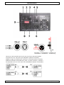 2
2
-
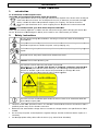 3
3
-
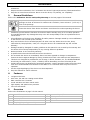 4
4
-
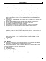 5
5
-
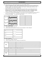 6
6
-
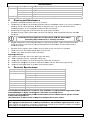 7
7
-
 8
8
-
 9
9
-
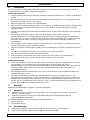 10
10
-
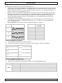 11
11
-
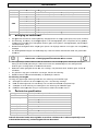 12
12
-
 13
13
-
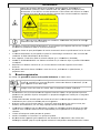 14
14
-
 15
15
-
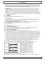 16
16
-
 17
17
-
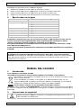 18
18
-
 19
19
-
 20
20
-
 21
21
-
 22
22
-
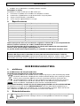 23
23
-
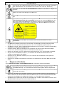 24
24
-
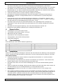 25
25
-
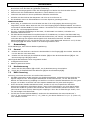 26
26
-
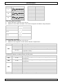 27
27
-
 28
28
-
 29
29
-
 30
30


HQ Power VARNA Manuel utilisateur
- Catégorie
- Stroboscopes
- Taper
- Manuel utilisateur
- Ce manuel convient également à
dans d''autres langues
- English: HQ Power VARNA User manual
- español: HQ Power VARNA Manual de usuario
- Deutsch: HQ Power VARNA Benutzerhandbuch
- Nederlands: HQ Power VARNA Handleiding
Documents connexes
-
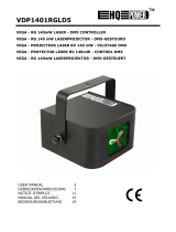 HQ Power VDP1401RGLD5 Manuel utilisateur
-
HQ Power KRYSTAL RGY260 spécification
-
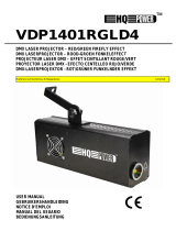 HQ Power VDP1401RGLD4 Manuel utilisateur
-
HQ Power VDPL300CB Manuel utilisateur
-
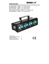 HQ Power VDPLW1601 Manuel utilisateur
-
HQ Power VDPL300MR ARUZO Manuel utilisateur
-
HQ Power LED QUAD FLOWER spécification
-
HQ Power Flowerstar Manuel utilisateur
-
HQ Power Music-controlled + DMX strobe 750W Manuel utilisateur
-
 HQ Power HQLE10028 Manuel utilisateur


