
KSS300
170690.0922/b
IMPORTANT
Read Before Using
IMPORTANT
Lire avant usage
IMPORTANTE
Leer antes de usar
Operating/Safety Instructions
Consignes d’utilisation/de sécurité
Instrucciones de funcionamiento y seguridad
For English Version
See page 2
Version française
Voir page 30
Versión en español
Ver la página 58

KSS300
2
09/2022
English
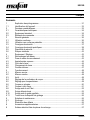
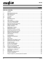
Table of contents
1 Signs and symbols ........................................................................................................... 3
1.1 Identification of the device ................................................................................................ 5
2 Product specifications ...................................................................................................... 5
2.1 Technical data .................................................................................................................. 6
2.2 Scope of delivery .............................................................................................................. 6
2.3 Adjustment elements ........................................................................................................ 7
3 General safety .................................................................................................................. 8
3.1 Intended use ..................................................................................................................... 8
3.2 Foreseeable misuse ......................................................................................................... 8
3.3 Safety instructions ............................................................................................................ 9
3.4 Specific safety rules ....................................................................................................... 10
3.5 Safety devices ................................................................................................................ 14
3.6 Residual risks ................................................................................................................. 15
4 Setup / adjustment ......................................................................................................... 15
4.1 Mains connection ........................................................................................................... 15
4.2 Routing of the connecting cable ..................................................................................... 15
4.3 Chip extraction ............................................................................................................... 16
4.4 Saw blade selection ....................................................................................................... 16
4.5 Changing the saw blade ................................................................................................. 16
4.6 Riving knife ..................................................................................................................... 19
5 Operation ........................................................................................................................ 20
5.1 Startup ............................................................................................................................ 20
5.2 Switching on ................................................................................................................... 20
5.3 Switching off ................................................................................................................... 20
5.4 Cutting depth setting ...................................................................................................... 21
5.5 Setting for bevel cuts ...................................................................................................... 21
5.6 Plunge cuts ..................................................................................................................... 22
5.7 Shadow gap cuts ............................................................................................................ 23
5.8 Sawing with the Flexi bar ............................................................................................... 24
5.9 Sawing along markings .................................................................................................. 25
5.10 Sawing with the parallel guide fence .............................................................................. 26
5.11 Working with the guiding device ..................................................................................... 27
6 Service and maintenance ............................................................................................... 27
6.1 Storage ........................................................................................................................... 27
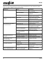
7 Troubleshooting .............................................................................................................. 27
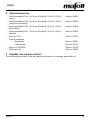
8 Optional accessories ...................................................................................................... 29
9 Exploded view and spare parts list ................................................................................. 29

KSS300
09/2022
3
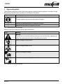
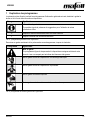
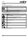
1 Signs and symbols
These operating instructions contain the following general information signs to guide you, the reader, through
the operating instructions and to provide you with important information.
Sign
Meaning
Important information
This sign highlights user tips and other useful information.
➢
Identifies an intermediate result in a sequence of actions.
✓
Identifies the final result of a sequence of actions.
Tab. 1: General signs and their meanings
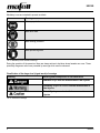
Warning icons warn of dangerous points, risks and obstacles.
Icon
Meaning
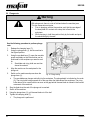
Warning
This icon can be found at all locations where you can find information regarding your
safety. Non-observance can result in extremely serious injuries.
Warns of danger of electric shock.
Warns of danger caused by dust.
Warns of the danger of cutting.
Warns of the danger of cutting off or severing limbs.
Tab. 2: Warning icons and their meanings

KSS300
4
09/2022
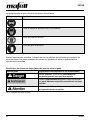
Mandatory icons are intended to prevent accidents.
Icon
Meaning
Wear eye protection.
Wear dust mask.
Wear hearing protection.
Wear protective gloves.
Tab. 3: Mandatory icons and their meanings
During the operation of the power tool there are always actions to be taken where hazards can occur. These
potentially dangerous actions are preceded by warnings which must be observed.
Classification of the danger level (signal words) of warnings
Warning
Meaning and consequences of non-observance
Imminent danger that will cause serious or fatal injuries.
Potentially dangerous situation that can cause serious or
fatal injuries.
Potentially dangerous situation that can cause minor
injuries.
Tab. 4: Structure of warnings

KSS300
09/2022
5
1.1 Identification of the device
The icons listed and explained below can be found on the rating plate or on the product.
Symbol
Explanation
Symbol
Explanation
V
Volt
1, 2, 3, ...
I, II, III, ...
Rotational speed setting
A
Ampere
rpm
Revolutions per minute
Hz
Hertz
ø
Saw blade diameter
W
Watt
~
Alternating current
kg
Kilogram (weight)
Protection class II
min
Minutes (time)
Read operating instructions
s
Seconds (time)
Protective goggles
n0
Rated speed at no load
Hearing protection
n
Rated speed at normal load
Dust mask
2 Product specifications
for machines with item number 916733
The article number and machine number are listed on the type plate of the machine.
By entering the article number and machine number on the MAFELL homepage, you can
call up the spare parts lists, exploded drawings, and other product information belonging
to your machine (see also Chapter 9 Exploded view and spare parts list).

KSS300
6
09/2022
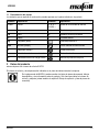
2.1 Technical data
Universal motor
120 V~, 60 Hz
Power consumption (normal load)
1000 W
Current at normal load
9.1 A
Saw blade speed at no load
8800 rpm
Saw blade speed at normal load
5690 rpm
Cutting depth 0°/30°/45°
42/36/29 mm [1.65/1.42/1.14 in]
Saw unit swivel range
0° to 45°
Saw blade diameter max/min
120/112 mm [4.72/4.41 in]
Saw blade body thickness
1.2 mm [0.05 in]
Tool cutting width
1.8 mm [0.07 in]
Saw blade mounting hole
20 mm [0.8 in]
Hose connector diameter
28 mm [1.10 in]
Weight without power cord, without parallel guide fence
2.3 kg [10.14 lbs]
Dimensions including guiding device
(width x length x height)
200 x 550 x 200 mm [7.87 x 21.65 x 7.87 in]
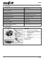
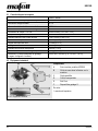
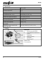
2.2 Scope of delivery
Fig. 1: Scope of delivery
Components
A
Hand-held circular saw KSS300
B
Allen key in a holder on the machine
C
Parallel guide fence
D
Transport box
E
Flexi bar
F
Guiding device S
Additionally included:
1 hose connector

KSS300
09/2022
7
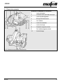
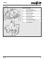
2.3 Adjustment elements
Fig. 2: Front and read adjustment elements
Adjustment elements on the machine
1
Plunge lever
2
Cutting depth scale
3
Pre-feed lever
4
Switch-on lock
5
Wing screws
6
Operating lever
7
Clamping lever
8
Tilting segment scale
9
Tilting segment wing screw
10
Locking pin

KSS300
8
09/2022
3 General safety
Please read all safety instructions and directions. Failure to comply with the safety instructions and
directions can cause electric shock, fire and/or serious injuries. Please retain all safety instructions and
directions for future reference.
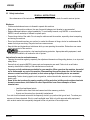
3.1 Intended use
The hand-held circular saw is only suitable for ripping and cross cutting of solid wood.
Panel material such as chip board, core board and medium density fiber board can also be processed.
Processing wood fiber insulation materials is also possible.
Use only saw blades that are approved by the manufacturer.
3.2 Foreseeable misuse
The machine is not intended for any other use than the intended use listed above.
The manufacturer is not liable for any damage resulting from such other use.
To use the machine as intended, comply with the operating, maintenance and repair conditions specified by
MAFELL.
Foreseeable misuse also includes:
- Tampering with, removing and/or bypassing safety devices of any kind.
- Operating the machine without safety devices.
- Non-observance of safety and warning instructions in the operating instructions.
- Removing the safety and warning labels from the machine.
- Operating the machine by unauthorized persons.
- Failure to follow prescribed maintenance and care instructions.
Never use:
- Cracked and/or deformed saw blades.
- Saw blades made of high speed steel (HSS saw blades).
- Blunt saw blades as they impose an excessive load on the motor.
- Saw blades with a base body thicker than or a cutting width smaller than the riving knife.
- Saw blades that are not suitable for the no load speed of the saw blade.
- Abrasive wheels.

KSS300
09/2022
9
3.3 Safety instructions
READ ALL INSTRUCTIONS!
Non-observance of the instructions listed below can cause electric shock, fire and/or serious injuries.
Work area
- Children and adolescents are not allowed to operate this machine.
- When using the machine outdoors, the use of an earth leakage circuit breaker is recommended.
- Replace damaged cables or plugs immediately. To avoid safety hazards, only MAFELL or an authorized
MAFELL service workshop is allowed to replace parts.
- Prevent sharp kinks of the cable. Do not wrap the cable around the machine, especially when transporting
and storing the machine.
- Do not use this machine when you are tired, or under the influence of drugs, alcohol or medicaments. Be
aware of what you are doing. Stay alert and use common sense.
- Keep children and bystanders at a distance while you are operating the machine. Distractions can cause
you to lose control of the machine.
- Use eye protection, dust mask and hearing protection. Appropriate safety equipment, used
under proper conditions, will reduce the risk of injuries.
Instructions for service and maintenance:
- Cleaning the machine regularly, especially the adjustment elements and the guiding devices, is an important
safety factor.
- Ensure that only genuine MAFELL spare parts and accessories are used. Failure to do so will make
warranty claims and the liability of the manufacturer null and void.
- Prepare a periodic maintenance schedule for your machine. When you clean the machine, be careful
not to disassemble any part of the machine. Reassembling the machine bears the risk that internal
wires are routed incorrectly or pinched, or that return springs of the safety device are mounted
incorrectly. Certain cleaning agents, such as gasoline, carbon tetrachloride, ammonia, etc. can damage
plastic parts.
- Some of the dust produced by sawing, sanding, drilling and other building work contains chemicals
known to cause cancer, birth defects or other reproductive harm. Some examples of these
chemicals are:
- Lead from lead-based paints,
- Crystalline silica from bricks and cement and other masonry products,
- Arsenic and chromium from chemically treated wood.
Your risk from this hazard varies with the frequency at which you perform this type of work. To reduce your
exposure to these chemicals: Work in a well-ventilated area. Work only with approved safety equipment,
such as dust masks that are specially designed to filter out particles of microscopic size.

KSS300
10
09/2022
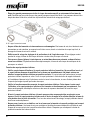
3.4 Specific safety rules
Sawing method
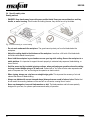
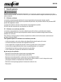
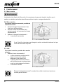
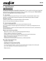
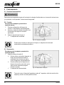
- DANGER: Keep hands away from cutting area and the blade. Keep your second hand on auxiliary
handle, or motor housing. If both hands are holding the saw, they cannot be cut by the blade.
Fig. 3: Incorrect sawing vs. correct sawing
- Do not reach underneath the workpiece. The guard cannot protect you from the blade below the
workpiece.
- Adjust the cutting depth to the thickness of the workpiece. Less than a full tooth of the blade teeth
should be visible below the workpiece.
- Never hold the workpiece in your hands or across your leg while cutting. Secure the workpiece to a
stable platform. It is important to support the work properly to minimize body exposure, blade binding, or
loss of control.
- Hold the power tool by insulated gripping surfaces, when performing an operation where the cutting
tool may contact hidden wiring or its own cord. Contact with a "live" wire will also make exposed metal
parts of the power tool "live" and could give the operator an electric shock.
- When ripping, always use a rip fence or straight edge guide. This improves the accuracy of cut and
reduces the chance of blade binding.
- Always use blades with correct size and shape (diamond versus round) of arbour holes. Blades that
do not match the mounting hardware of the saw will run off-centre, causing loss of control.
- Never use damaged or incorrect blade washers or bolt. The blade washers and bolt were specially
designed for your saw, for optimum performance and safety of operation.

KSS300
09/2022
11
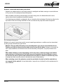
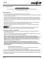
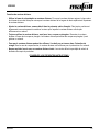
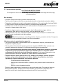
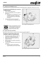
Kickback - causes and related safety instructions
- Kickback is a sudden reaction to a pinched, jammed or misaligned saw blade, causing an uncontrolled saw
to lift up and out of the workpiece toward the operator;
- When the blade is pinched or jammed tightly by the kerf closing down, the blade stalls and the motor
reaction drives the unit rapidly back toward the operator;
- If the blade becomes twisted or misaligned in the cut, the teeth at the back edge of the blade can dig into the
top surface of the wood causing the blade to climb out of the kerf and jump back toward the operator.
Fig. 4: Kickback of the machine
Kickback is the result of saw misuse and/or incorrect operating procedures or conditions and can be avoided
by taking proper precautions as given below.
- Maintain a firm grip with both hands on the saw and position your arms to resist kickback forces.
Position your body to either side of the blade, but not in line with the blade. Kickback could cause the
saw to jump backwards, but kickback forces can be controlled by the operator, if proper precautions are
taken.
- When blade is binding, or when interrupting a cut for any reason, release the trigger and hold the
saw motionless in the material until the blade comes to a complete stop. Never attempt to remove
the saw from the work or pull the saw backward while the blade is in motion or kickback may occur.
Investigate and take corrective actions to eliminate the cause of blade binding.
- When restarting a saw in the workpiece, centre the saw blade in the kerf so that the saw teeth are
not engaged into the material. If a saw blade binds, it may walk up or kickback from the workpiece as the
saw is restarted.

KSS300
12
09/2022
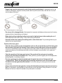
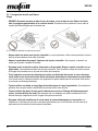
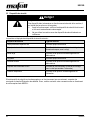
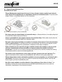
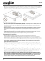
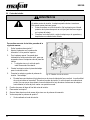
- Support large panels to minimise the risk of blade pinching and kickback. Large panels tend to sag
under their own weight. Supports must be placed under the panel on both sides, near the line of cut and
near the edge of the panel.
Fig. 5: Incorrect support vs. correct support
- Do not use dull or damaged blades. Unsharpened or improperly set blades produce narrow kerf causing
excessive friction, blade binding and kickback.
- Blade depth and bevel adjusting locking levers must be tight and secure before making the cut. If
blade adjustment shifts while cutting, it may cause binding and kickback.
- Use extra caution when sawing into existing walls or other blind areas. The protruding blade may cut
objects that can cause kickback.
Function of the lower guard
- Check the lower guard for proper closing before each use. Do not operate the saw if the lower guard
does not move freely and close instantly. Never clamp or tie the lower guard into the open position.
If the saw is accidentally dropped, the lower guard may be bent. Raise the lower guard with the retracting
handle and make sure it moves freely and does not touch the blade or any other part, in all angles and
depths of cut.
- Check the operation of the lower guard spring. If the guard and the spring are not operating
properly, they must be serviced before use. Lower guard may operate sluggishly due to damaged parts,
gummy deposits, or a build-up of debris.
- The lower guard may be retracted manually only for special cuts such as "plunge cuts" and
"compound cuts". Raise the lower guard by the retracting handle and as soon as the blade enters
the material, the lower guard must be released. For all other sawing, the lower guard should operate
automatically.
- Always observe that the lower guard is covering the blade before placing the saw down on bench or
floor. An unprotected, coasting blade will cause the saw to walk backwards, cutting whatever is in its path.
Be aware of the time it takes for the blade to stop after switch is released.

KSS300
09/2022
13
Function of the riving knife
- Use the appropriate saw blade for the riving knife. For the riving knife to function, the body of the blade
must be thinner than the riving knife and the cutting width of the blade must be wider than the thickness of
the riving knife.
- Adjust the riving knife as described in this instruction manual. Incorrect spacing, positioning and
alignment can make the riving knife ineffective in preventing kickback.
- Always use the riving knife except when plunge cutting. The riving knife must be replaced after plunge
cutting. The riving knife causes interference during plunge cutting and can create kickback.
- For the riving knife to work, it must be engaged in the workpiece. The riving knife is ineffective in
preventing kickback during short cuts.
- Do not operate the saw if the riving knife is bent Even a light interference can slow the closing rate of a
guard.
RETAIN THESE INSTRUCTIONS!

KSS300
14
09/2022
3.5 Safety devices
Danger
Risk of injury from missing safety devices
These devices are necessary for the safe operation of the machine. They must
not be removed or rendered ineffective.
➢ Check the proper functioning of the safety devices before you start
operating the machine.
➢ Never use the machine with missing or ineffective safety devices.
The machine is equipped with the following safety devices:
Safety device
Type of check
Upper fixed guard
Visual check for damage
Lower movable guard
Functional check (complete opening and jerk-free
abrupt closing)
Large base plate
Visual check for damage and deformation
Handles
Visual check for damage
Riving knife/splitter
Visual check for damage and deformation
Switching device and brake
Functional check (braking time must not be longer
than 7 seconds)
Hose connector
Visual check for damage and obstruction
If the safety devices are damaged or not functioning properly, follow the instructions in the chapter
Troubleshooting. For other malfunctions, please contact your dealer or MAFELL Customer Service directly.

KSS300
09/2022
15
3.6 Residual risks
Warning
Risk of injury when working with the machine
Even when the machine is used as intended and in compliance with the safety
regulations, there are still residual risks caused by the intended use, which can
have consequences for your health.
➢ Observe the safety instructions and information in these instructions.
➢ Always be extremely careful and cautious when you work with the machine.
The existing residual risks include:
- Contact with the saw blade in the area of the start-up opening below the base plate.
- Contact with the part of the saw blade that protrudes below the workpiece during the cutting process.
- Contact with rotating parts from the side: Saw blade, clamping flange and flange bolt.
- Kickback of the machine when jammed in the workpiece.
- Breakage and ejection of the saw blade or parts of the saw blade.
- Impaired hearing when working without hearing protection for long periods of time.
- Emission of harmful wood dusts during longer operation without extraction.
- FLEXI bar snapping open in case of improper use.
4 Setup / adjustment
4.1 Mains connection
Prior to starting up the machine, check to ensure that the mains voltage corresponds to the operating voltage
specified on the rating plate of the machine.
4.2 Routing of the connecting cable
Warning
Electric shock when cutting into the connecting cable
The connecting cable can impair safety functions and work functions and
get into contact with the cutting tool. Cutting into the connecting cable of
the machine puts the metal parts of the machine under tension and
causes an electric shock. There is a risk of injury for the user.
➢ When working, pay attention to the way the connecting cable is
routed.
➢ Never cut into the connecting cable of your machine.

KSS300
16
09/2022
4.3 Chip extraction
Caution
Health hazards from wood dust
The dusts produced during work can be inhaled and can cause health damage.
➢ Harmful dust must be extracted with a HEPA 13 dust extractor.
➢ Wear a dust mask during work.
For all work that produces a significant amount of dust, connect the machine to a suitable external extraction
device. The air velocity must be at least 20 m/s [65 ft/sec].
The outside diameter of the hose connector is 28 mm [1.1 in].
4.4 Saw blade selection
To achieve good cutting quality, use a sharp tool and select a tool from the following list that is appropriate for
material and application:
Cutting softwood and hardwood across and along the grain direction:
- Carbide circular saw blade Ø 120 x 1.8 x 20 mm, 24 teeth [Ø 4.72 x 0.07 x 0.79 in]
Cutting softwood and hardwood especially along the grain direction:
- Carbide circular saw blade Ø 120 x 1.8 x 20 mm, 12 teeth [Ø 4.72 x 0.07 x 0.79 in]
Cutting softwood and hardwood especially across the grain direction:
- Carbide circular saw blade Ø 120 x 1.8 x 20 mm, 40 teeth [Ø 4.72 x 0.07 x 0.79 in]
Cutting laminate:
- Carbide circular saw blade Ø 120 x 1.8 x 20 mm, 40 teeth [Ø 4.72 x 0.07 x 0.79 in]
Cutting wood fiber insulation material:
- Carbide circular saw blade Ø 120 x 1.8 x 20 mm, 40 teeth [Ø 4.72 x 0.07 x 0.79 in]
Cutting plastic material (styrofoam):
- Carbide circular saw blade Ø 120 x 1.8 x 20 mm, 24 teeth [Ø 4.72 x 0.07 x 0.79 in]
4.5 Changing the saw blade
Caution
Risk of injury from the sharp saw blade
The saw blade is sharp. You can hurt yourself when you change the saw blade.
➢ Wear protective gloves when you change the saw blade.
➢ Be careful when you change the saw blade.

KSS300
09/2022
17
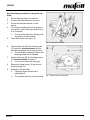
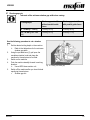
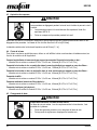
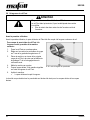
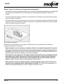
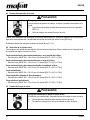
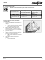
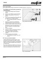
Use the following procedure to change the saw
blade:
1. Pull out the power plug of the machine.
2. Put down the cable where you can see it.
3. Put the disconnected machine on a flat
surface.
4. To move the movable guard to the maximum
open position, either use the pre-feed lever (3)
or do it manually.
➢ To remove the saw blade, manually hold
the guard in the open position.
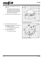
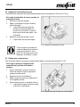
5. Press and hold the locking pin (10).
Fig. 6: Locking the saw shaft
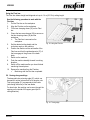
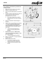
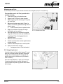
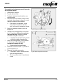
6. Insert the Allen key (B) into the flange screw
(11) and turn it counterclockwise until the
saw shaft locks home into the locking device.
➢ The saw blade is retained in position and
the flange screw can be released.
7. Using the Allen key (B), turn the flange screw
(11) counterclockwise to loosen it.
➢ You can now release the locking pin.
8. Remove the flange screw (11) and the front
clamping flange (12).
9. Remove the old saw blade.
➢ Clamping flanges must be free of
adhering parts!
➢ The new saw blade can now be installed.
Fig. 7: Removing the old saw blade

KSS300
18
09/2022
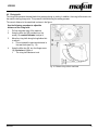
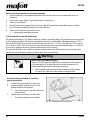
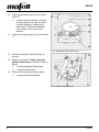
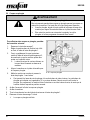
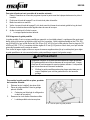
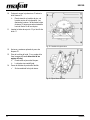
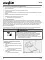
10. Position the new saw blade (13) on the rear
flange (15).
➢ Ensure that the direction of rotation is
correct when you install the saw blade.
The saw teeth or the arrow on the saw
blade (13) must point in the direction of
the arrow (14) on the machine.
11. Fit clamping flange (12) and flange screw (11).
Fig. 8: Replacing the saw blade
12. Press and hold the locking pin (10).
13. Using the Allen key (B), turn the flange screw
(11) clockwise to tighten it.
➢ You can now release the locking pin.
➢ The saw blade is secured.
14. Close the movable guard.
✓ The saw blade is changed.
Fig. 9: Securing the saw blade

KSS300
09/2022
19
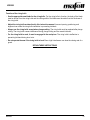
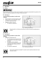
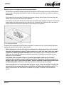
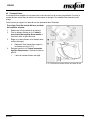
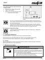
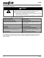
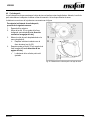
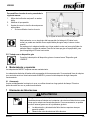
4.6 Riving knife
The riving knife prevents the saw blade from jamming during rip cutting. In addition, the riving knife retracts into
the machine during plunge cuts. This prevents kickback during the sawing process.
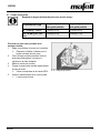
The correct distance to the saw blade is shown in the figure.
Use the following procedure to adjust the
distance of the riving knife:
1. Pull out the power plug of the machine.
2. Using the Allen key (B) provided, turn the
screw (16) counterclockwise to adjust it.
3. Move the riving knife along its longitudinal slot
to adjust it.
➢ Do not exceed the maximum distance to
the saw blade (see Fig.. 10).
4. Using the Allen key (B), turn the flange screw
(16) clockwise to tighten it.
✓ The riving knife distance is set.
Fig. 10: Distance riving knife to saw blade

KSS300
20
09/2022
5 Operation
5.1 Startup
These operating instructions must be brought to the attention of all persons entrusted with the operation of the
machine, with particular emphasis on the chapter "Safety instructions".
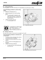
5.2 Switching on
Use the following procedure to switch on the
machine:
1. Press the switch-on lock (4) forward to unlock.
2. With the switch-on lock depressed, actuate
and hold the operating lever (6).
3. Release the switch-on lock (4).
✓ The machine is switched on
Fig. 11: Switching the machine on
Since the switch is not latching, the machine runs only as long as the operating lever is
pressed.
5.3 Switching off
Use the following procedure to switch off the
machine:
1. Release the operating lever (6).
➢ The integrated automatic brake limits the
coasting time of the saw blade to approx.
5 seconds.
➢ The switch-on lock is activated
automatically and secures the hand-held
circular saw against being switched on
inadvertently.
✓ The machine is switched off.
Fig. 12: Switching the machine off
As soon as the braking time exceeds 7 seconds, have the machine checked and a new
brake pad installed.
La page charge ...
La page charge ...
La page charge ...
La page charge ...
La page charge ...
La page charge ...
La page charge ...
La page charge ...
La page charge ...
La page charge ...
La page charge ...
La page charge ...
La page charge ...
La page charge ...
La page charge ...
La page charge ...
La page charge ...
La page charge ...
La page charge ...
La page charge ...
La page charge ...
La page charge ...
La page charge ...
La page charge ...
La page charge ...
La page charge ...
La page charge ...
La page charge ...
La page charge ...
La page charge ...
La page charge ...
La page charge ...
La page charge ...
La page charge ...
La page charge ...
La page charge ...
La page charge ...
La page charge ...
La page charge ...
La page charge ...
La page charge ...
La page charge ...
La page charge ...
La page charge ...
La page charge ...
La page charge ...
La page charge ...
La page charge ...
La page charge ...
La page charge ...
La page charge ...
La page charge ...
La page charge ...
La page charge ...
La page charge ...
La page charge ...
La page charge ...
La page charge ...
La page charge ...
La page charge ...
La page charge ...
La page charge ...
La page charge ...
La page charge ...
La page charge ...
-
 1
1
-
 2
2
-
 3
3
-
 4
4
-
 5
5
-
 6
6
-
 7
7
-
 8
8
-
 9
9
-
 10
10
-
 11
11
-
 12
12
-
 13
13
-
 14
14
-
 15
15
-
 16
16
-
 17
17
-
 18
18
-
 19
19
-
 20
20
-
 21
21
-
 22
22
-
 23
23
-
 24
24
-
 25
25
-
 26
26
-
 27
27
-
 28
28
-
 29
29
-
 30
30
-
 31
31
-
 32
32
-
 33
33
-
 34
34
-
 35
35
-
 36
36
-
 37
37
-
 38
38
-
 39
39
-
 40
40
-
 41
41
-
 42
42
-
 43
43
-
 44
44
-
 45
45
-
 46
46
-
 47
47
-
 48
48
-
 49
49
-
 50
50
-
 51
51
-
 52
52
-
 53
53
-
 54
54
-
 55
55
-
 56
56
-
 57
57
-
 58
58
-
 59
59
-
 60
60
-
 61
61
-
 62
62
-
 63
63
-
 64
64
-
 65
65
-
 66
66
-
 67
67
-
 68
68
-
 69
69
-
 70
70
-
 71
71
-
 72
72
-
 73
73
-
 74
74
-
 75
75
-
 76
76
-
 77
77
-
 78
78
-
 79
79
-
 80
80
-
 81
81
-
 82
82
-
 83
83
-
 84
84
-
 85
85


