
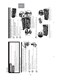
TC
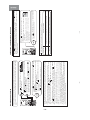
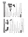
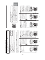
SERVICE MANUAL
TECHNICAL INFORMATION
INFORMATIONS TECHNIQUES
REFER TO THE FOUNDATION MANUAL
REPORTEZ-VOUS AU MANUEL DE BASE
ROOM AIR CONDITIONER
SPECIFICATIONS AND PARTS ARE SUBJECT TO CHANGE FOR IMPROVEMENT
LES SPECIFICATIONS ET PIECES DETACHEES PEUVENT CHANGER POUR ETRE AMELIOREES.
FOR SERVICE PERSONNEL ONLY
RESERVE AU PERSONNEL
NO. 0788EF
RAS-25SX8 / RAC-25SX8
RAS-35SX8 / RAC-35SX8
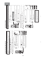
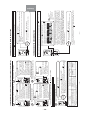
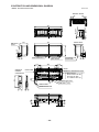
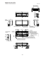
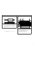
798
295
233
11.5
750 (+86)
570
288 (+56)
36
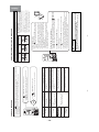
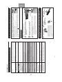
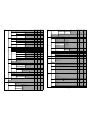
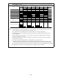
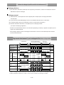
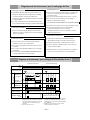
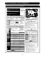
RAS-25SX8 RAC-25SX8
1ø, 220V - 230V, 50Hz
465 (70 - 960)
2.49 - 2.38
2.5 (0.5 - 3.4)
8,533 (1,707 - 11,604)
585 (65 -1,410)
3.13 - 2.99
3.2 (0.6 - 5.8)
10,922 (2,048 - 19,795)
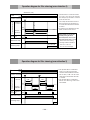
798
295
233
11.5
750 (+86)
570
288 (+56)
36
RAS-35SX8 RAC-35SX8
1ø, 220V - 230V, 50Hz
835 (70 - 1,350)
4.47 - 4.27
3.5 (0.5 - 4.1)
11,946 (1,707 - 13,993)
875 (65 -1,490)
4.68 - 4.48
4.2 (0.5 - 6.1)
14,335 (1,707 - 20,819)
RAS-25SX8
RAS-35SX8
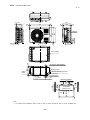
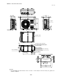
RAC-25SX8
RAC-35SX8
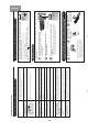
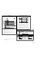
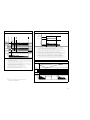
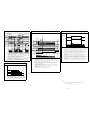
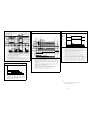
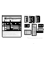
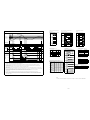
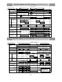
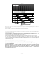
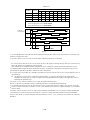
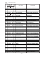
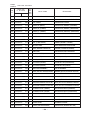
SPECIFICATIONS
CARACTERISTIQUES GENERALES
SPECIFICATIONS
CARACTERISTIQUES GENERALES
HOW TO USE
UTILISATION
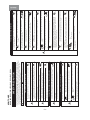
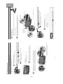
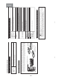
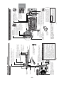
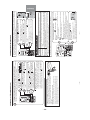
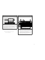
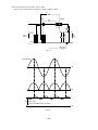
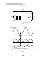
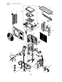
CONSTRUCTION AND DIMENSIONAL DIAGRAM
DIMENSIONS DES UNITÉS
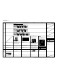
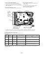
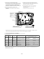
MAIN PARTS COMPONENT
PRINCIPAUX COMPOSANTS
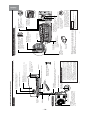
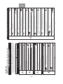
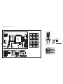
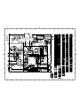
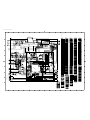
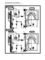
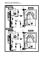
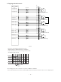
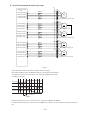
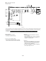
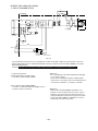
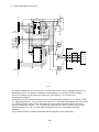
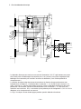
WIRING DIAGRAM
SCHÉMA ÉLECTRIQUE
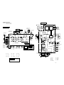
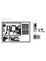
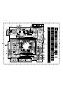
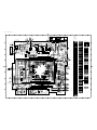
WIRING DIAGRAM OF THE PRINTED WIRING BOARD
SCHÉMA ÉLECTRIQUE DU CIRCUIT IMPRIMÉ
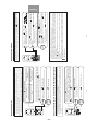
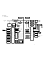
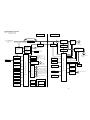
BLOCK DIAGRAM
ORGANIGRAMME DE CONTRÔLE
BASIC MODE
MODE DE BASE
REFRIGERATING CYCLE DIAGRAM
SCHÉMA DU CYCLE DE RÉFRIGÉRATION
PROCÉDURE D'ASSEMBLAGE ET DESASSEMBLAGE
DESCRIPTION OF MAIN CIRCUIT OPERATION
DESCRIPTION DES PRINCIPAUX CIRCUITS
SERVICE CALL Q&A
MODE OPERATOIRE DE DEPANNAGE
TROUBLE SHOOTING
DETECTION DES PANNES
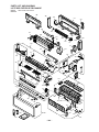
PARTS LIST AND DIAGRAM
LISTE DES PIÉCES DE RECHANGE
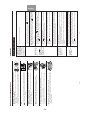
CONTENTS
TABLE DES MATIERES
INDOOR UNIT + OUTDOOR UNIT
DECEMBER 2008 Hitachi Appliances, Inc.
8
9
60
64
67
71
83
87
150
152
158
198
214
280
OUTDOOR UNIT
UNITÉ EXTÉRIEURE
INDOOR UNIT
UNITÉ INTÉRIEURE
After installation Après installation
DC INVERTER INVERSEUR C.C.
COOLING
RÉFRIGÉRATION
HEATING
CHAUFFAGE
TYPE TYPE
MODEL
POWER SOURCE
TOTAL INPUT
TOTAL AMPERES
CAPACITY
TOTAL INPUT
TOTAL AMPERES
CAPACITY
DIMENSIONS
NET WEIGHT
MODÈLE
SOURCE D'ALIMENTATION
(PHASE/TENSION/FREQUENCE)
PUISSANCE ABSORBEE TOTALE
AMPERES TOTAUX
CAPACITE
PUISSANCE ABSORBEE TOTALE
AMPERES TOTAUX
CAPACITE
DIMENSIONS
(mm)
POIDS NET
(A)
(B.T.U./h)
W, L
H, H
D, P
(kg)
(kW)
(A)
(B.T.U./h)
(kW)
(W)
(W)
INDOOR UNIT
UNITÉ INTÉRIEURE
OUTDOOR UNIT
UNITÉ EXTÉRIEURE
INDOOR UNIT
UNITÉ INTÉRIEURE
OUTDOOR UNIT
UNITÉ EXTÉRIEURE

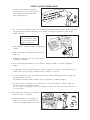
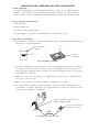
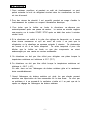
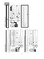
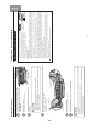
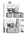
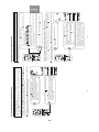
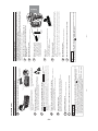
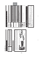
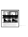
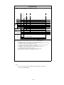
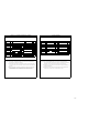
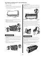
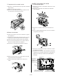
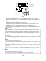
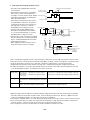
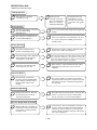
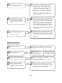
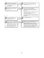
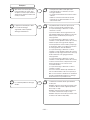
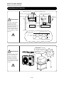
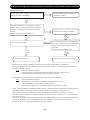
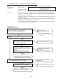
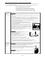
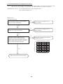
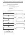
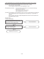
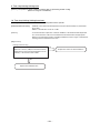
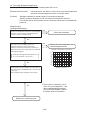
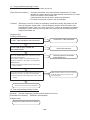
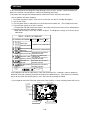
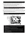
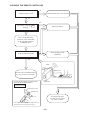
1. In order to disassemble and repair the
unit in question, be sure to disconnect the
power cord plug from the power outlet
before starting the work.
2. If it is necessary to replace any parts, they should be replaced with respective genuine parts for the unit,
and the replacement must be effected in correct manner according to the instructions in the Service
Manual of the unit.
3. After completion of repairs, the initial state should be
restored.
4. Lead wires should be connected and laid as in the
initial state.
5. Modification of the unit by the user himself should
absolutely be prohibited.
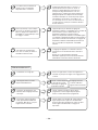
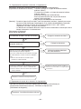
6. Tools and measuring instruments for use in repairs or inspection should be accurately calibrated in
advance.
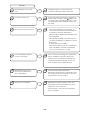
7. In installing the unit having been repaired, be careful to prevent the occurrence of any accident such as
electrical shock, leak of current, or bodily injury due to the drop of any part.
8. To check the insulation of the unit, measure the insulation resistance between the power cord plug and
grounding terminal of the unit.
The insulation resistance should be 1MΩ or more as measured by a 500V DC megger.
9. The initial location of installation such as window, floor or the other should be checked for being safe
enough to support the repaired unit again.
If it is found not so strong and safe, the unit should be installed at the initial location after reinforced or
at a new location.
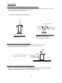
10. Any inflammable object must not be placed
about the location of installation.
11. Check the grounding to see whether it is
proper or not, and if it is found improper,
connect the grounding terminal to the earth.
Spray
gasoline
gasbombe
thinner
SAFETY DURING REPAIR WORK
If the contacts of electrical
parts are defective, replace
the electrical parts without
trying to repair them
1
2
3
4
5

– 1 –
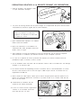
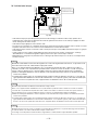
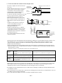
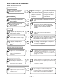
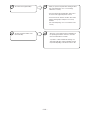
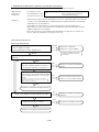
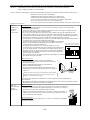
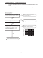
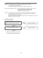
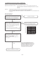
1. Avant de procéder à une réparation, veillez
à couper l'alimentation électrique.
2. Les pièces de rechange doivent être des pièces d'origine et le remplacement des pièces doit être réalisé
conformément aux instructions figurant dans le manuel d'entretien.
3. Après achèvement des réparations, les conditions
initiales doivent être rétablies.
4. Après toute intervention, le raccordement et le
cheminement des câbles électriques doivent être
rétablis comme à l'origine.
5. Toute modification au niveau de l'installation ne peut être effectuée que par une personne compétente.
Toute intervention ou modification par l'utilisateur lui-même est par conséquent à proscrire.
6. Les outils et les appareils de mesure qui doivent être employés pour effectuer l'entretien auront été
préalablement réglés ou étalonnés comme il convient.
7. Lors de l'installation d'une unité ayant subi une réparation, veillez à éviter tout accident dû à une décharge
électrique ou la chute d'un objet.
8. Pour vérifier l'isolement de l'appareillage, mesurer la résistance entre le cordon d'alimentation et la borne
de masse. Cette résistance doit au moins être égale à 1MΩ lorsque la mesure est effectuée avec un
mégohmmètre de 500V CC.
9. Avant la fixation de l'unité réparée, vérifiez que les fixations d'origine peuvent supporter l'appareil. Si ces
fixations vous paraissent défectueuses, renforcez-les si possible et dans le cas contraire, l'unité doit être
fixée à un autre endroit.
10. L'emplacement de l'installation doit être
éloigné de toute matière inflammable.
11. La mise à la masse doit être soigneusement
contrôlée; en cas de défaut, la borne de
masse doit être mise à la terre.
Il faut d'abord que je coupe
I'alim
entation électrique.
Aérosol
Essence
Dilunt
Bonbonne de gaz
PRECAUTIONS RELATIVES A LA SECURITE PENDANT LES REPARATIONS
Si vous constatez que les contacts d'un
composant électrique sont défectueux,
remplacez le composant et ne tentez pas
de réparer les contacts.
1
2
3
4
5

– 2 –
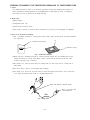
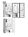
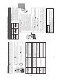
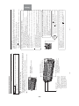
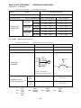
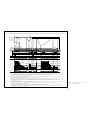
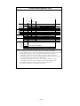
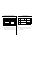
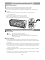
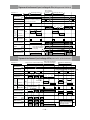
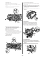
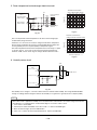
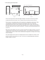
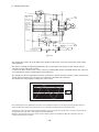
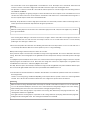
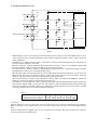
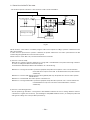
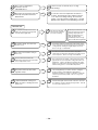
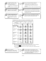
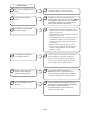
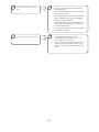
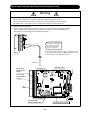
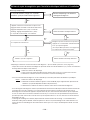
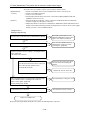
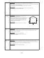
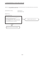
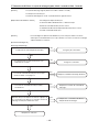
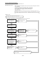
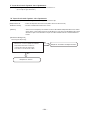
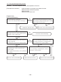
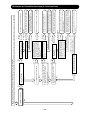
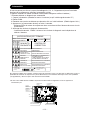
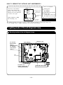
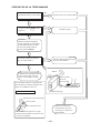
WORKING STANDARDS FOR PREVENTING BREAKAGE OF SEMICONDUCTORS
1. Scope
The standards provide for items to be generally observed in carrying and handling semiconductors in
relative manufactures during maintenance and handling thereof. (They apply the same to handling of
abnormal goods such as rejected goods being returned.)
2. Object parts
(1) Microcomputer
(2) Integrated circuits (I.C.)
(3) Field effective transistor (F.E.T.)
(4) P.C. boards or the like to which the parts mentioned in (1) and (2) of this paragraph are equipped.
3. Items to be observed in handling
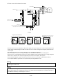
(1) Use a conductive container for carrying and storing of parts. (Even rejected goods should be handled in
the same way.)
(2) When any part is handled uncovered (in counting, packing and the like), the handling person must
always use himself as a body earth. (Make yourself a body earth by passing one M ohm earth
resistance through a ring or bracelet.)
(3) Be careful not to touch the parts with your clothing when you hold a part even if a body earth is
being taken.
(4) Be sure to place a part on a metal plate with grounding.
(5) Be careful not to fail to turn off power when you repair the printed circuit board. At the same time,
try to repair the printed circuit board on a grounded metal plate.
H
I
T
A
C
H
I I
C
4
0
1
T
H
1
,
1
8
8
U
V
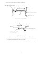
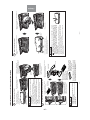
Fig. 1 Conductive container
A conductive polyvinyl bag
IC
IC
Conductive sponge
Fig. 2 Body earth
Body earth (Elimik conductive band)
Clip for connection with
a grounding wire
1MΩ

– 3 –
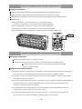
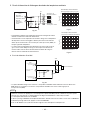
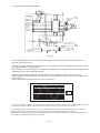
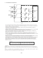
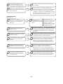
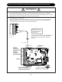
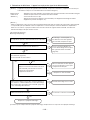
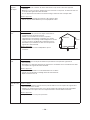
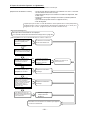
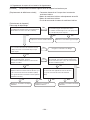
PREVENTION DES DOMMAGES AUX SEMI-CONDUCTEURS
1. Champ d'application
Pour éviter d'endommager les semi-conducteurs utilisés dans les unités, lors de chaque intervention
d'entretien ou de réparation, vous devez observer des précautions spéciales. Les mêmes précautions
doivent être prises lors de la manipulation d'organes défectueux qui doivent être retournés en usine.
2. Pièces détachées de l'appareillage.
(1) Microprocesseur
(2) Circuits intégrés (C.I.)
(3) Transistor à effet de champ (T.E.C)
(4) Circuits imprimés sur lesquels se trouvent implantés les composants (1) et (2).
3. Précautions de manipulation
(1) Pour transporter ou stocker un semi-conducteur, placez-le dans un emballage conducteur. Procéder de
même avec un composant défectueux.
(2) Lorsque vous maniqulez des composants qui ne sont pas protégés (par exemple pour les compter ou
les emballer), vous devez veiller à ce que votre corps soit électriquement relié à la terre. Pour cela,
portez un bracelet conducteur. Reliez le bracelet à une résistance de 1MΩ et celle-ci à la terre par
l'intermédiaire d'un conducteur.
(3) Veillez en outre à ce que vos vêtements ne viennent jamais en contact avec le composant même si
votre corps est relié à la terre.
(4) Déposez le composant sur une surface métallique correctement mise à la terre.
(5) Sous aucun prétexte, n'omettez de couper l'alimentation avant de procéder à une réparation sur un
circuit imprimé. Par ailleurs, l'intervention sur le circuit imprimé doit se faire alors que celui-ci repose
sur une surface métallique mise à la masse.
H
I
T
A
C
H
I IC
4
0
1
T
H
1
,
1
8
8
U
V
Fig. 1 Emballage conducteur
Sac en polyvinyle
conducteur
C.I.
C.I.
Eponge
conductrice
Fig. 2 Mise à la terre du corps
Bracelet de mise à la terre du corps
(Bande conductrice Elimik)
Pince de connexion avec
fil de mise à la terre
1MΩ

– 4 –
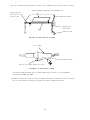
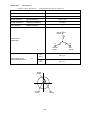
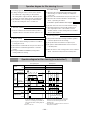
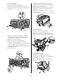
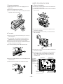
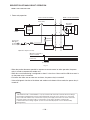
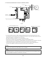
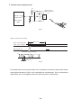
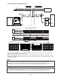
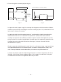
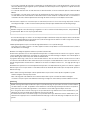
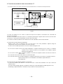
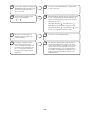
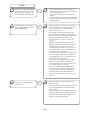
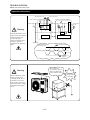
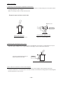
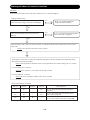
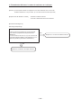
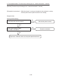
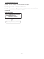
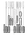
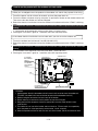
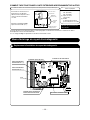
(6) Use a three wire type soldering iron including a grounding wire.
Fig.4 Grounding a solder iron
Use a high insulation mode (100V, 10MΩ or higher) when ordinary iron is to be used.
(7) In checking circuits for maintenance, inspection, or some others, be careful not to have the test probes
of the measuring instrument shortcircuit a load circuit or the like.
Bare copper wire (for body earth)
Metal plate (of Al. stainless steel, etc.)
Working table
Resistor 1MΩ(1/2W)
Earth wirte
Staple
Fig.3 Grounding of the working table
soldering iron
Grounding wire
Screw stop at the screwed
part using a rag plate

– 5 –
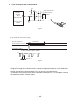
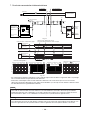
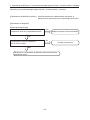
(6) Le fer à souder doit être alimenté par un câble à trois conducteurs (dont un pour la mise à la terre).
Fig.4 Mise à la terre d'un fer à souder
Vous pouvez également utiliser un fer à souder ordinaire dans la mesure où il est parfaitement
isolé (au moins 10MΩ sous 100V).
(7) Pendant le contrôle des circuits au cours des opérations d'entretien ou d'inspection, évitez à tout prix la
mise en court-circuit de la charge par les pointes de contact de l'appareil de mesure.
Fil de cuivre nu
(pour mise à la
terre du corps)
Surface métallique (aluminium, acier inoxydable, etc.)
Plan de travail
Résistance de
1MΩ (1/2W)
Câble de masse
Agrafe
Fig.3 Mise à la terre d'un plan de travail
fer à souder
Câble de masse
Poser ici une rondelle éventail et la visser

– 6 –
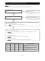
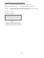
1. In quiet operation or stopping the running, its heard slight flowing noise of
refrigerant in the refrigerating cycle occasionally, but this noise is not abnormal
for the operation.
2. When it thunders near by, it is recommend to stop the operation and to
disconnect the power cord plug from the power outlet for safety.
3. The room air conditioner dose not start automaticaly after recovery of the
electric power failure for preventing fuse blowing. Re-press START / STOP
button after 3 minutes from when unit stopped.
4. If the room air conditioner is stopped by adjusting thermostat, or missoperation,
and re-start in a moment, there is occasion that the cooling and heating
operation does not start for 3 minutes, it is not abnormal and this is the result
of the operation of IC delay circuit. This IC delay circuit ensures that there is
no danger of blowing fuse or damaging parts even if operation is restarted
accidentally.
5. This room air conditioner should not be used at the cooling operation when the
outside temperature is below 22˚C (72˚F).
6. This room air conditioner (the reverse cycle) should not be used when the
outside temperature is below –20˚C (–4˚F).
If the reverse cycle is used under this condition, the outside heat exchanger is
frosted and efficiency falls.
7. When the outside heat exchanger is frosted, the front is melted by operating
the hot gas system, it is not trouble that at this time fan stops and the vapour
may rise from the outside heat exchanger.
CAUTION

– 7 –
1. Dans certaines conditions et pendant un arrêt de fonctionnement, on peut
parfois entendre le bruit du réfrigérant circulant dans les canalisations; ce bruit
n'a rien d'anormal.
2. Pour des raisons de sécurité, il est conseillé, pendant un orage, d'arrêter le
fonctionnement du système en coupant l'alimentation électrique.
3. Pour éviter que le fusible ne fonde, le climatiseur ne démarre pas
automatiquement après une panne de secteur. La remise en marche suppose
une pression sur la touche START / STOP après un délai d'au moins 3 minutes
suivant l'arrêt.
4. Si le climatiseur est arrêté à la suite d'un réglage de thermostat, ou à cause
d'une fausse manoeuvre et qu'il est remis en route, il se peut que la
réfrigération ou le chauffage ne reprenne qu'après 3 minutes. Ce phénomène
est normal et dû à un relais temporisé. Ce relais temporisé a pour rôle
d'éviter que le fusible ne fonde ou que des composants ne soient
endommagés par une remise en service accidentelle.
5. Ce climatiseur ne doit pas être utilisé pour réfrigérer une pièce lorsque la
température extérieure est inférieure à 22˚C (72˚F).
6. Ce climatiseur ne doit pas être utilisé lorsque la température extérieure est
inférieure à –20˚C (–4˚F).
En effet, dans ce cas, l'échangeur de chaleur extérieur gèle et le rendement
chute considérablement.
7. Quand l'échangeur de chaleur extérieur est givré, les gaz chauds peuvent
entraîner une vaporisation de l'eau accumulée sur la face avant. Ce n'est pas
un problème si à ce moment-là le ventilateur s'arrête et il se peut que de la
vapeur se dégage de l'échangeur de chaleur extérieur.
ATTENTION

– 8 –
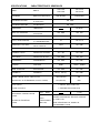
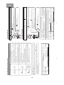
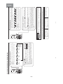
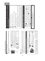
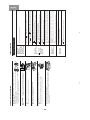
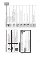
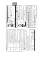
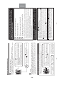
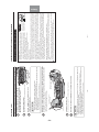
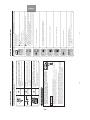
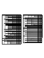
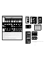
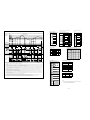
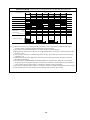
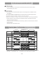
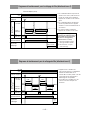
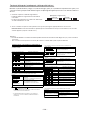
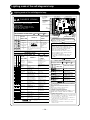
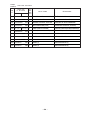
MODEL
FAN MOTOR
FAN MOTOR CAPACITOR
FAN MOTOR PROTECTOR
COMPRESSOR
OVER HEAT PROTECTOR
OVERLOAD RELAY
FUSE (for MICRO COMPUTER)
POWER RELAY, STICK RELAY
POWER SWITCH
TEMPORARY SWITCH
TEST SWITCH
TRANSFORMER
VARISTOR
NOISE SUPPRESSOR
THERMOSTAT
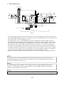
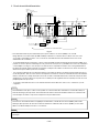
REFRIGERANT CHARGING VOLUME
(R410A)
CHARGE EN RÉFRIGÉRANT
(R410A)
UNIT UNITÉ
PIPES
CANALISATIONS
(MAX. 20m)
SPECIFICATIONS CARACTERISTIQUES GENERALES
MODÈLE
MOTEUR DE VENTILATEUR
COMPRESSEUR
RELAIS DE SURCHARGE
INTERRUPTEUR D'ALIMENTATION
INTERRUPTEUR AUXILIAIRE
INTERRUPTEUR DE TEST
TRANSFORMATEUR
VARISTANCE
ANTIPARASITAGE
THERMOSTAT
CONDENSATEUR DE MOTEUR
DE VENTILATEUR
PROTECTION DU MOTEUR
DE VENTILATEUR
PROTECTION CONTRE LES
SURCHAUFFES
FUSIBLE
(pour MICROPROCESSEUR)
RELAIS DE PUISSANCE,
RELAIS AUTOEXCITE
REMOTE CONTROL SWITCH (LIQUID CRYSTAL)
INTERRUPTEUR DE TÉLÉCOMMANDE (CRISTAUX LIQUIDES)
YES (RAR-3R5)
OUI (RAR-3R5)
NO
NON
FUSE CAPACITY
CALIBRE DE FUSIBLE
30W (DC280V)
NO NON
NO NON
3A
G4AS
YES OUI
NO NON
NO NON
450NR
NO NON
YES (IC) OUI (IC)
47W (DC380V)
EU1013E1
YES OUI
YES OUI
25A, 2A, 1A
NO NON
NO NON
YES OUI
NO NON
450NR, TND05V
NO NON
NO NON
WITHOUT REFRIGERANT BECAUSE COUPLING
IS FLARE TYPE.
SANS RÉFRIGÉRANT EN RAISON DU
RACCORDEMENT FLARE.
A INRUSH - WITH STAND TYPE
A RETARDE-AVEC STAND TYPE
NO NON
NO NON
NO NON
1,190g
RAS-25SX8
RAS-35SX8
RAC-25SX8
RAC-35SX8

– 9 –
HOW TO USE
MODEL RAS-25SX8 / RAC-25SX8, RAS-35SX8 / RAC-35SX8
– 2 –
• Please read the “Safety Precaution” carefully before operating the unit to ensure correct usage of the unit.
• Pay special attention to signs of “
Warning” and “ Caution”. The “Warning” section contains matters which, if
not observed strictly, may cause death or serious injury. The “Caution” section contains matters which may result
in serious consequences if not observed properly. Please observe all instructions strictly to ensure safety.
• The signs indicate the following meanings. (The following are examples of signs.)
• Please keep this manual after reading.
PRECAUTIONS DURING OPERATION
WARNING
WARNING
SAFETY PRECAUTION
• Do not reconstruct the unit.
Water leakage, fault, short circuit or fi re may occur if you reconstruct the unit by
yourself.
• Please ask your sales agent or qualified technician for the installation of your unit.
Water leakage, short circuit or fire may occur if you install the unit by yourself.
• Please use earth line.
Do not place the earth line near water or gas pipes, lightning-conductor, or the
earth line of telephone. Improper installation of earth line may cause electric
shock or fi re.
• Be sure to use the specifi ed piping set for R410A. Otherwise, this may result in
broken copper pipes or faults.
• A circuit breaker should be installed depending on the mounting site of the unit.
Without a circuit breaker, the danger of electric shock exists.
• Do not install the unit near a location where there is fl ammable gas. The outdoor
unit may catch fi re if fl ammable gas leaks around it. Piping shall be suitable
supported with a maximum spacing of 1m between the supports.
• Please ensure smooth fl ow of water when installing the drain hose.
• Make sure that a single phase 220-230V power source is used.
The use of other power sources may cause electrical components to overheat
and lead to fi re.
PRECAUTIONS DURING INSTALLATION
PROHIBITION
CONNECT EARTH LINE
PROHIBITION
WARNING
CAUTION
• Avoid an extended period of direct airfl ow for your health.
• Should abnormal situation arise (like burning smell), please stop operating the
unit and remove plug from the socket. Contact your agent. Fault, short circuit or
fi re may occur if you continue to operate the unit under abnormal situation.
• Please contact your agent for maintenance. Improper self maintenance may cause electric
shock and fi re.
• Please contact your agent if you need to remove and reinstall the unit. Electric shock or fi re
may occur if you remove and reinstall the unit yourself improperly.
PRECAUTIONS DURING SHIFTING OR MAINTENANCE
• Do not use any conductor as fuse wire, this could cause fatal accident.
• During thunder storm, disconnect the plug top and turn off the circuit
breaker.
• Do not put objects like thin rods into the panel of blower and suction side
because the high-speed fan inside may cause danger.
• Spray cans and other combustibles should not be located within a meter of the
air outlets of both indoor and outdoor units.
As a spray can’s internal pressure can be increased by hot air, a rupture may result.
PROHIBITION
PROHIBITION
PROHIBITION
PROHIBITION
“OFF”
“OFF”
This sign in the fi gure indicates prohibition. Indicates the instructions that must be followed.
PROHIBITION
– 3 –
ENGLISH
• Do not place plants directly under the airfl ow as it is bad for the plants.
• Do not direct the cool air coming out from the air-conditioner panel to face
household heating apparatus as this may affect the working of apparatus such
as the electric kettle, oven etc.
• The product shall be operated under the manufacturer specifi cation and not
for any other intended use.
PRECAUTIONS DURING OPERATION
CAUTION
• Do not attempt to operate the unit with wet hands, this could cause fatal
accident.
• When operating the unit with burning equipments, regularly ventilate
the room to avoid oxygen insuffi ciency.
• Please ensure that outdoor mounting frame is always stable, fi rm and without
defect. If not, the outdoor unit may collapse and cause danger.
• Do not wash the unit with water or place a water container such as a vase on
the indoor unit.
Electrical leakage could be present and cause electric shock.
• Be sure to stop the operation by using the remote controller and turn off the
circuit breaker during cleaning, the high-speed fan inside the unit may cause
danger.
• Turn off the circuit breaker if the unit is not be operated for a long period.
• Do not climb on the outdoor unit or put objects on it.
• When operating the unit with the door and windows opened, (the room
humidity is always above 80%) and with the air defl ector facing down or moving
automatically for a long period of time, water will condense on the air defl ector
and drips down occasionally. This will wet your furniture. Therefore, do not
operate under such condition for a long time.
• If the amount of heat in the room is above the cooling or heating capability of
the unit (for example: more people entering the room, using heating equipments
and etc.), the preset room temperature cannot be achieved.
• Indoor unit cleaning must be performed by authorized personnel only. Consult
your sales agent.
Using a commercially available detergent or similar can damage the plastic
parts or clog the drain pipe, causing water to drip with potential electric shock
hazard.
• Do not touch the air outlet, bottom surface and aluminium fi n of the outdoor
unit.
You may get hurt.
• Do not touch the refrigerant pipe and connecting valve.
Burns may result.
PROHIBITION
DON’T WET
PROHIBITION
PROHIBITION
PROHIBITION
DON’T TOUCH
“OFF”
PROHIBITION
PROHIBITION
PROHIBITION
PROHIBITION
PROHIBITION
DON’T TOUCH
STRICTLY OBSERVE
PRECAUTIONS
“OFF”

– 10 –
– 4 –
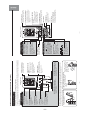
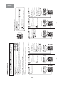
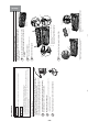
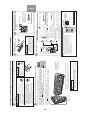
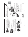
INDOOR UNIT
OUTDOOR UNIT
Micro Mesh Stainless Filter (internal)
Catches dusts in the air. (Page 37)
Titanium Heat Exchanger (internal)
Movable Panel
This panel opens during the operation and closes
when operation stop.
(It may not open on certain operation mode.)
Signal Receiver (internal)
Receive signal from the
remote control.
Indicator
Front Panel
(Page 8)
Horizontal/Vertical Air Deflector (internal)
Air Outlet
Remote Controller
Pipe/Wiring
Drain Hose
Drains dehumidified water generated from the indoor unit when in
the cooling, dehumidifying and dry cool modes.
Air Inlet (rear and left side)
Earth Terminal
(side bottom)
Drain Port (bottom)
Air Outlet
Discharges cool air when in heating
mode and warm air when in cooling
and dry cool modes, and warm or
cold air when in the dehumidifying
mode.
Remote Controller Holder
To fix the remote controller
on the wall or pillar.
• Even if the operation is stopped, the outdoor
to cool down the electrical parts.
• In heating operation, condensed water and
defrosted water is discharged from the outdoor
unit. Do not block the drain port as the water in
the drain may freeze in a cold area.
• Even during cooling operation, the water
condensed in the pipe, etc. may flow out from
the outdoor unit.
• When installing the outdoor unit under eaves,
etc. of the apartment, install a bush and drain
pipe on the drain port for drainage treatment.
ABOUT OUTDOOR UNIT
(Understanding The Operating Mechanism, page 43)
NAMES AND FUNCTIONS OF EACH PART
unit fan continues to rotate for 10-60 seconds
– 5 –
ENGLISH
( )
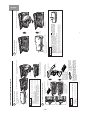
INDOOR UNIT CONTROL PANEL / CLEANING UNIT
Open the front panel to operate. (How to open the front panel, page 8)
Anti-mold Wasabi Cassette
Releases anti-mold elements
with wasabi fragrance to
prevent mold from growing
on dust inside the dust box.
(Page 8)
Dust Catcher
Collects the dust swept by
the cleaning unit. (At front
and top.) (Page 39)
Front Panel
Electric Dust Collector
Electrode
Releases negative ions to catch
pollens and dust in the air.
(Page 42)
Cleaning Unit
Cleans the dust
caught by the micro
mesh stainless filter.
Electric Dust
Collector Electrode
Ionized Mist Generator
(Located inside the air outlet.)
(Page 42)
Air Quality Sensor
Detects pollution of air (such as cigarette
smoke) when the air quality monitoring
operation is set. (Page 21)
Temporary Switch (Force-Cool switch)
If the remote controller does not
work due to battery failure,
press this switch to start
operation. (Page 49)
Force-cooling operation starts if this
switch is pressed for more than
5 seconds. This operation is allowed
to sales agents only. Users must not
perform this operation. (Page 49)
Dust Box
Collects and keeps the dust
that has been cleaned.
(Page 36)
Dust is collected
in this portion.
• While the power is on, a very small amount of power is
consumed within the control circuit even when the unit
is not in operation.
Power can be saved if the circuit breaker is switched off.
CAUTION
Pull out the power plug if the unit is not in
use for a long period.
(Or turn off the circuit breaker.)

– 11 –
– 6 –
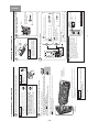
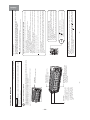
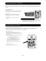
REMOTE CONTROLLER
Tr ansmits the operation and timer settings to the indoor unit.
The LCD shown in the illustration below is the display immediately after the reset switch is pressed. Usually not
all the data are displayed. On the LCD shown below, the functions not available for this room air conditioner are
also displayed.
Tr ansmission Part
Tr ansmission Indicator
The transmission indicator
lit when a signal is sent.
ROOM TEMPERATURE
Button
Press this button to set the
room temperature. Keep
pressing and the value will
change more quickly.
(Page 13, 14)
HUMIDITY Button
Press this button to set the
humidity for dehumidify and
dry cool operations.
(Page 14)
START/STOP Button
Press this button to start
operation. Press again to stop
operation.
HEAT Button
Press this button to start
heating operation.
(Page 15)
DEHUMIDIFY Button
Press this button to start
dehumidifying operation.
(Page 15)
COOL Button
Press this button to start
cooling operation.
(Page 17)
DRY COOL Button
Press this button to start dry
cool operation. (Page 17)
BUTTONS TO
START OPERATIONS
Remote controller can be used when it is fixed on a wall or pillar using the remote controller holder.
Before fixing it, make sure the indoor unit can be controlled from the remote controller fixing point.
Attach the remote controller
• Insert from above.
Take out the remote controller
• To remove, hold the upper part
of the remote controller and
pull it up.
• Do not remove the remote
controller by twisting it left
and right. Doing so could
result in coming off of the
rear cover.
PROHIBITION
SLEEP TIMER Operation Button
Press this button to start sleep timer
operation. (Page 31)
IONIZED MIST Operation Button
Press this button to start ionized mist
operation. (Page 18)
Screw
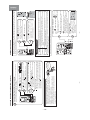
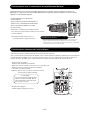
NAMES AND FUNCTIONS OF EACH PART (continued)
– 7 –
ENGLISH
RAR-3R5
(When the door is open)
Operation Selector
Press this button to select the
operation mode. (Page 13, 14)
VERTICAL AIRFLOW Button
Use this button to swing the
vertical air deflector or to adjust
the angle to your preference.
(Page 25)
HORIZONTAL AIRFLOW
Button
Use this button to swing the
horizontal air deflector or
to adjust the angle to your
preference. (Page 26, 27)
PREFERENCE Button
Press this button to select your
preferred mode. (Page 23, 24)
TIMER Buttons
SET TIME Button
Use this button to set and
check the current time.
(Page 11)
RESET Button
Press this button after the
batteries are replaced and
when the air conditioner does
not function properly. (Page 11)
MANUAL CLEAN Button
Starts filter cleaning operation
while the air conditioner
operation is stopped. (Page 34)
AIR PURIFYING Button
Press this button to start
stainless plasma air purifying
(FAN) operation.
(Page 18)
BUTTONS TO
START OPERATIONS
FAN SPEED Button
Press this button to select
fan speed. (Page 13, 14)
These are preset functions
except for
(SAVE).
Preset can be done if these
buttons are pressed while the
air conditioner is stopped,
however, the unit will not
function accordingly.
FUNCTION SELECTOR
Buttons
Each time when you press,
blinking changes in the
following sequence (page 12,
19, 20, 21, 22):
ON/OFF Button
Use this button to set or cancel
the function selected by the
function selector.
FUNCTION SELECTOR

– 12 –
– 8 –
Open the front panel.
• Do not hold the movable panel
when opening and closing the
front panel.
Movable panel
Front panel
Gripping part
Panel support
• Hold and lift up the front panel.
• Push up the panel support until it
clicks to lock it.
• Lower the front panel and fix in
position with the panel support.
CAUTION
•
Do not use excessive force to open and close the movable
panel.
This may cause it to malfunction.
(The movable panel automatically open and close when the power
is ON/OFF and START/STOP.
)
•
Do not open the front panel during operation
.
It may interrupt the movable panel to work properly. Be sure to stop
the operation first before opening the front panel.
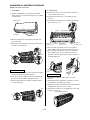
Install the anti-mold wasabi cassette.
• Pull out the anti-mold wasabi
cassette case.
• Take out the anti-mold wasabi
cassette from the aluminium bag.
Anti-mold wasabi
cassette
Aluminium bag
Anti-mold wasabi
cassette case
• Hold the anti-mold wasabi
cassette with the handle
side toward you, and then
install it into the unit.
• Slide the anti-mold
wasabi cassette that
has been taken out of
the wrapper directly
into the anti-mold
wasabi cassette case.
Do not remove or tear
the aluminium sheet on
the surface nor make a
hole on it.
CAUTION
• Do not put your face close to the package when you
open it.
Your eyes or nose may be irritated by wasabi aroma.
• Do NOT eat.
1
2
No daily maintenance is required. However,
the effectiveness of anti-mold wasabi cassette
will be lost after approximately 10 years have
elapsed. Replace the anti-mold wasabi cassette
in such event.
INSTALLING ANTI-MOLD WASABI CASSETTE
– 9 –
ENGLISH
1 12
Close the front panel.
• Hold and lift up the front panel.
CAUTION
• If the front panel is not closed properly, the (CLEAN) indicator
blinks during filter cleaning operation and stainless plasma air
purifying operation. These operations will not perform properly if the
front panel is not closed securely. Also, the movable panel will not
work properly on cooling operation, etc.
• If the front panel is loose, it may come off and drop.
• When opening the front panel upwards, please do not use excessive force.
If the front panel comes off the device, this may cause it to malfunction.
• When the front panel remains open, be sure to push up the panel
support.
• Push down the panel support until it clicks.
• Push the both ends of the front panel first and
then its center until it clicks.
• Pull it downward.
3
Front panel
Movable panel

– 13 –
– 10 –
Make sure the power plug is firmly plugged into the power outlet.
WARNING
• Be sure to use the power outlet exclusively for
air conditioner
Use of other power outlet may cause heat, which
could result in fire.
• Make sure that dust is not deposited on the
power plug and be sure to plug in until the blades
of the plug are fully inserted to avoid unstable
plug-in and dust from being accumulated
Use of air conditioner with dusty power plug or
improper power connection could result in electrical
shock or fire.
CAUTION
Do not operate with
wet hands
It may cause electric
shock.
Compulsory
Wet Hand
Prohibited
Performing operation check after the power is turned on.
Perform the filter cleaning unit operation check
• After the power is turned on (after the power plug is inserted into the power outlet or
after the circuit breaker is switched on after power failure), the cleaning unit makes
one cycle of back and forth movement.
• At this time, the
(CLEAN) indicator is lit.
• One cycle of operation check will take approximately 7 minutes.
• During the operation check, the unit performs “Fan” operation while the movable panel and
horizontal air deflector remain closed.
• If the
(CLEAN) indicator blinks (lit for 4 seconds/off 1 second) after the operation check,
refer to “Troubleshooting” on page 45.
Cleaning Unit
There is a filter
cleaning wiper inside.
Dust catcher
CAUTION
Do not put your fingers or a stick etc into the top surface during
the filter cleaning operation
It may result in injury or malfunction.
• The illustration shows the unit without front panel for your reference
only.
During the actual operation, the filter cleaning is not performed if
the front panel is open.
1
2
Compulsory
FILTER CLEANING UNIT OPERATION CHECK
– 11 –
ENGLISH
Address
Address
RAR-3R5
RAR-3R5
Install the batteries.
• Use two AAA-size alkaline batteries.
Set the current time (Ex: set to 1:30 p.m.)
RESET
1
2
Press the (TIMER) button to adjust to the current time.
• You can fast forward the time by continuously pressing the
button.
Confirm the current time
• Press the
(SET TIME) button to check the current time. If
necessary, readjust the time following the above procedure and
.
• Address selector switch is used to prevent
remote controller signal interference in such
circumstance where 2 indoor units are used in
the same room. This switch is not usually used.
(The factory setting is at “A” side.)
For this setting, please make an inquiry to your
sales agent.
Address selector
switch
Switch lever
Remote controller
backside
Do not operate by yourself.
Push mark
and pull.
ABOUT ADDRESS SELECTOR SWITCH
Time is incremented
Time is decremented
Press
(SET TIME) button to set the current time.
• “AM” or “PM” is lit instead of
blinking. It automatically goes
off in 10 seconds.
1
2
Open the cover and press the RESET
button with a sharp tip item.
3
• 18:88 lights up on the current
time display and “AM” and
“PM” start blinking.
CAUTION
1. Do not mix new and old batteries, or
different type of batteries together.
2. Remove the batteries when you do
not use the remote controller for 2 or 3
months.
PREPARE THE REMOTE CONTROLLER

– 14 –
– 12 –
RAR-3R5
1
While (SAVE) is blinking, point the remote controller towards
the unit and press the
(ON/OFF) button.
• A short beep sounds and (SAVE) indicator turns on.
Press the
(FUNCTION SELECTOR)
button until
(SAVE) blinks.
Press the
(FUNCTION SELECTOR) button again until
(SAVE) blinks.
While
(SAVE) is blinking, point the remote controller towards
the unit and press the
(ON/OFF) button.
• A short beep sounds and
(SAVE) indicator turns off, indicates
the setting is released.
Notes for “save” setting
• If ampere is set to “Save”, the maximum heating capacity slightly lowers
and starting up of heating operation will take a little longer. Besides,
the preset temperature may not be reached if outside temperature is
low. (If ampere is set to
(SAVE), the air conditioner will be in limited
operation at 6(A)).
• Point the remote controller to the signal receiver of the unit
Signal reception distance is approximately 7m in front of the unit.
However, this distance may be shorter or the signal may not be
receivable if there is an electronic lighting device in the same room.
• Handle the remote controller with care
Dropping it or getting it wet may compromise its signal transmission
capability. After new batteries are inserted into the remote controller,
the unit require approximately 10 seconds before it can respond to
commands and begin operation.
WHEN OPERATING THE REMOTE CONTROLLER
Approximately
7m from the front
Ampere setting (Standard/Save) can be selected.
If you experience frequent circuit breaker tripping, set ampere to “Save” to avoid this problem.
(Ampere is set to “Standard” at the time of purchase.)
4
2
RELEASE
PREPARE THE REMOTE CONTROLLER (continued)
– 13 –
ENGLISH
• Performs heating operation when the room temperature is below 23°C.
Set the temperature to be around 23°C.
• Performs dehumidifying operation when the room temperature is 23-26°C.
The preset temperature will be the room temperature at the time of start of air conditioner
operation.
• Performs cooling operation when the room temperature is above 27°C.
Set the temperature to be around 27°C.
RAR-3R5
RAR-3R5
Press the (OPERATION SELECTOR) button
to set the operation mode to auto.
• Every time you press it, the mode will change as
shown in the chart on the right.
Press the
(START/STOP) button.
Based on the room temperature and outside temperature, the unit determines the most suitable operation
mode (heating, dehumidifying or cooling) and a comfortable temperature. (Set the current time on the remote
controller before starting operation.)
Press the
(START/STOP) button again.
• A short beep sounds and the automatic
operation stops.
• Operation mode will be displayed on the
remote controller display.
Adjust the room temperature
Press the (ROOM TEMPERATURE)
button.
• Every time you press it, a short beep sounds and the
temperature will change by 1°C.
• is displayed if the temperature is set higher than
the automatically set room temperature by 1°C.
is displayed if the temperature is set lower than the
automatically set room temperature by 1°C.
• The adjustable temperature range is not higher or lower
than 3°C of the automatically set room temperature.
• Humidity setting cannot be adjusted.
Increase
Decrease
B
eep
Room temperature and fan speed can be adjusted to your preference.
Select the fan speed
Press the (FAN SPEED) button.
• “AUTO”, “LOW” and “SILENT”
can be selected.
• Every time you press it, the
mode will change as shown in
the chart on the right.
1
2
1
2
STOP
AUTOMATIC OPERATION
Heating
Dehumidifying
Cooling
Even if dehumidifying operation is set, the air conditioner may not execute dehumidifying if the room humidity
is not very high. This is not a malfunction.
AUTOMATIC OPERATION

– 15 –
– 14 –
RAR-3R5
RAR-3R5
Select the operation mode.
Press the (OPERATION
SELECTOR) button.
•
Any one of Heating/Dehumidifying/
Cooling/Dry Cool/Auto can be selected.
• To start fan operation, perform
stainless plasma air purifying
(FAN) operation. (Page 18)
•
If the (OPERATION SELECTOR)
button is pressed during operation,
a double short beep is heard on auto
mode while a single short beep is
heard on other mode.
Set the fan speed.
Set the room temperature.
Set the humidity (only for
dehumidifying and dry cool modes).
Operation starts.
Press the (START/STOP) button.
Press the
(START/STOP) button again.
• A short beep sounds and the operation stops.
• From next time, the operation that has been set on the above procedure -
can be performed just by pressing the
(START/STOP) button.
Humidity setting range
40-70%
Remote controller temperature setting range
Heating, Cooling, Dry Cool 16-32° C
Dehumidifying 10-32°C
2
1
One of them lights up. One of them lights up.
Press the (HUMIDITY) button.
• The humidity can be set in
increments of 5%.
• Humidity indication disappears in
approximately 10 seconds if the
operation is not started.
Increase
Decrease
4
3
Lights up.
Lights up.
5
STOP
•
Outdoor temperature -20°C-21°C
(When it is below
-20°C
or over 24°C, the heating
function may not operate in order to protect the
device.)
Heating Dehumidifying Dry Cool Cooling
•
Outdoor temperature
1°C-35°C
(Operation does not start if the
room temperature is below 1°C. )
• Outdoor
temperature
25°C-35°C
• Outdoor
temperature
22°C-43°C
• Do not use cooling operation in winter.
Press the (FAN SPEED) button.
• Any one of “AUTO”, “HI”, “MED”,
“LOW”, “SILENT” can be selected.
Fan speed indication disappears
in approximately 10 seconds if the
operation is not started.
• If the
(FAN SPEED) button is
pressed during operation, a double
short beep is heard on auto mode
while a single short beep is heard
on other mode.
Press the (ROOM
TEMPERATURE) button.
•
Room temperature indication
disappears in approximately 10 seconds
if the operation is not started.
• If the (ROOM TEMPERATURE)
button is pressed during operation,
a double short beep is heard at
20°C, a triple short beep at 30°C,
and a single short beep on other
temperature.
Increase
Decrease
Use the air conditioner following the operation conditions outlined below.
MANUAL OPERATION (HEATING, DEHUMIDIFYING, COOLING, DRY COOL)
– 15 –
ENGLISH
( (MIST/AIR
PURIFYING) indicators also
turn on during quick laundry
operation.)
Press the (HEAT) button to start heating operation.
3 types of dehumidifying operations can be performed by pressing the
(DEHUMIDIFY) button.
Performs powerful dry operation without lower down the room temperature.
Condensation
Control
• In auto dehumidifying mode, fine adjustment of room temperature (page 13),
humidity adjustment and fan speed selection (page 14) can be made to your
preference. Every time you press the ROOM TEMPERATURE button, the temperature
will change by 1°C. (Temperature setting range is not higher or lower than 3°C.) Every
time you press the HUMIDITY button, the humidity will change by 5%. (Humidity setting
range is 40%-70%.)
• In quick laundry mode, fine adjustment of room temperature (page 13) and fan
speed selection (page 14) can be made to your preference. (Fine adjustment of
room temperature and humidity adjustment cannot be made in condensation
control mode.)
Press the
(HEAT) button.
• Adjust the room temperature and fan speed to your preference.
Temperature range between 16°C-32°C can be set. (Page 14)
Press the
(START/STOP) button.
• A short beep sounds and heating operation stops.
Press the
(DEHUMIDIFY) button.
• Every time you press the
(DEHUMIDIFY) button, the
mode will change as shown in the chart below.
Press the
(START/STOP) button.
• A short beep sounds and dehumidifying operation stops.
• After the dehumidifying operation is stopped, the remote controller will display
the operation mode that had been set before the
(DEHUMIDIFY) button was
pressed.
(“AUTO” flashes for 5 seconds)
Auto
Dehumidifying
Quick
Laundry
STOP
STOP
HEATING OPERATION
DEHUMIDIFYING OPERATION

– 16 –
– 16 –
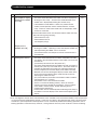
Auto
Dehumidifying
Operation mode In this situation Operating mechanism
• In damp
weather
• In most of the cases, the room temperature at the time the button is
pressed becomes the preset temperature.
(When room temperature is below 12°C, set 13°C. When it is
temperature. When it is above 26°C, set 26°C)
• Ta rget humidity is around 50-60%. If the humidity becomes lower than
the target value, operation stops. If it becomes higher than the target
value, operation resume.
• The operation mode may automatically be switched to cooling or
heating for temperature control. (Refer to table below)
• To dry the
laundry
quickly
• Detects outdoor temperature, room temperature and humidity to
automatically select the most suitable combination of heating and
powerful dehumidifying operations.
• This operation is performed together with stainless plasma air purifying
operation.
• Priority is given to laundry drying.
Be sure use this mode when no one is in the room as the room
temperature and humidity will be high temporarily.
• 3-hour timer function is used for this operation mode.
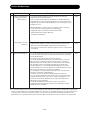
• When
controlling
condensation
formed on
windows in
winter time
• Be careful when condensation control operation is performed if the outside temperature is low as it will lower the
room temperature.
•
(OFF TIMER) and (ON TIMER) (page 28), which are to be set using clock function, are not available during
dehumidifying (quick laundry and condensation control modes) operation. However, the timer (for 30 minutes
and 1-9 hours) can be set for quick laundry and condensation control modes with the
(SLEEP) button.
• To set to your desired temperature and humidity while executing dehumidifying, it is recommended to use manual
dehumidifying function. (Page 14)
• If you do not wish room temperature to be too high when drying the laundry, use the preference (Powerful) mode
instead of quick laundry mode. (Page 24)
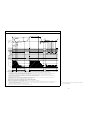
The operation mode may automatically be switched to cooling or heating for temperature control.
At this time, the room humidity may vary by approximately 10%.
Heating
operation
Dehumidifying operation
Operation
stop
Cooling
operation
About 3
°C
Approx. 3°C if outside temp. is
below approx. 32°C.
Approx. 1°C if outside temp. is
above approx. 32°C.
Room temperature set
Current room temperature
1ºC
• To control the condensation, priority is given to the operation for
lowering humidity. Therefore, the room temperature goes down in
this operation mode. The operation stops if the room temperature
becomes 1°C or below.
• 2-hour timer function is used for this operation mode.
Condensation
Control
Quick Laundry
DEHUMIDIFYING OPERATION (continued)
13°C-22°C, set +2°C. When it is below 23°C-26°C, set room
– 17 –
ENGLISH
(“AUTO” flashes for 5 seconds)
Press the (COOL) button to start cooling operation.
When you operates cooling operation with the dry function, press the (DRY COOL) button, the air conditioner
automatically sets temperature and humidity in dry cool mode.
Press the (COOL) button.
• Adjust the room temperature and fan speed to your preference. (Page 14)
Temperature range between 16°C-32°C can be set.
Press the
(START/STOP) button.
• A short beep sounds and dry cool operation stops.
Press the
(DRY COOL) button.
• Adjust the room temperature (page 13) and fan speed (page 14) to your
preference.
• Every time you press the
(ROOM TEMPERATURE) button, the
temperature will change by 1°C.
(Temperature setting range from the auto set temperature is not higher or
lower than 3°C.)
• Humidity setting cannot be adjusted.
Humidity
to be set
Temperature
to be set
Based on the detected outside and room temperature,
the temperature is set on an hourly basis within the range
of 24-28°C.
• Even if the room temperature
reached the preset temperature,
the air conditioner may continue
to operate if the preset humidity
has not been reached.
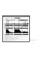
Dry
intermittent
operation
Dry Cool operation
Operation
stops
Cooling
operation
About 3°C
Approx. 3°C if outside temp. is
below approx. 32°C.
Approx. 1°C if outside temp. is
above approx. 32°C.
Room temperature set Current room temperature
50% when temperature above 27°C is set.
55% when temperature of 26°C is set.
60% when temperature below 25°C is set.
About 1°C
The operation mode may automatically be switched to cooling or heating for temperature control.
If the room temperature is lower than the preset temperature, intermittent operation (repeat of operation state
and stop state) is performed to avoid excessive lowering of temperature and to control the humidity.
Press the
(START/STOP) button.
• A short beep sounds and cooling operation stops.
STOP
STOP
COOLING OPERATION
DRY COOL OPERATION

– 17 –
– 18 –
Position of horizontal
air deflector
Wide airflow angle
The angle set for the current
operation mode
• Stainless plasma air purifying and ionized mist operations have an effect of reducing unpleasant smell of the
wall and curtain in the room and controlling bacteria suspended in the air.
• If the ionized mist operation is set while the air conditioner is in operation, the ionized mist operation will
operate together with another operation.
Ionized mist is generated using the air in the room. It may not be generated depending on the temperature
and humidity. (It may take approximately 30 minutes to 1 hour for ionized mist generation. )
• Stainless plasma air purifying (Fan) operation is the combined operation mode of the fan operation and the
electric dust collector operation.
• If the stainless plasma air purifying mode is set while the air conditioner is in basic operation mode, the air
purifying function by the electric dust collector will operate together.
Press the
(START/STOP) button.
• A short beep sounds and ionized mist operation stops.
• Adjust the fan speed to your preference. “HI”, “MED”, “LOW”, “SILENT” can be
selected. (Page 14)
• When only ionized mist operation is set,
(OFF TIMER) and (ON TIMER)
preset cannot be done.
Press the
(IONIZED MIST) button.
Press the
(IONIZED MIST) button.
Press the
(START/STOP) button.
• A short beep sounds and stainless plasma air purifying operation
stops.
Press the
(AIR PURIFYING) button.
Press the
(AIR PURIFYING) button.
• Adjust the fan speed to your preference. “HI”, “MED”, “LOW”, “SILENT” can
be selected. (Page 14)
• When only stainless plasma air purifying operation is set,
(OFF TIMER)
and
(ON TIMER) preset cannot be done.
STOP
STOP
CANCEL
during
operation
CANCEL
during
operation
Operation mode
Ionized mist operation only
When operate together with
another operation
IONIZED MIST OPERATION
STAINLESS PLASMA AIR PURIFYING (FAN) OPERATION
– 19 –
ENGLISH
RAR-3R5
Press the (FUNCTION SELECTOR) button again until
(INTERNAL CLEAN) blinks.
While
(INTERNAL CLEAN) is blinking, point the remote controller
towards the unit and press the
(ON/OFF) button.
• A short beep sounds and
(INTERNAL CLEAN) indicator turns off
on the remote controller.
STOP
The internal cleaning operation is automatically performed after cooling, dehumidifying or dry cool operation to
control mold growth by configuring the
(INTERNAL CLEAN) operation. (There is no mold removing function
and disinfecting/sterilizing effect.)
Press the
(FUNCTION SELECTOR) button
until
(INTERNAL CLEAN) blinks.
While
(INTERNAL CLEAN) is blinking, point the remote controller
towards the unit and press the
(ON/OFF) button.
• A short beep sounds and
(INTERNAL CLEAN) indicator turns on
at the remote controller.
• It will automatically stop after 1 hour of operation.
1
2
• Internal cleaning operation is not performed if the duration of cooling, dehumidifying or dry cool operation is
too short (below approximately 10 minutes).
• If the internal cleaning mode is set, the internal cleaning operation will automatically start when cooling,
dehumidifying or dry cool operation is stopped. During internal cleaning, the heating operation and fan operation
(with stainless plasma air purifying) are performed to control the mold growth inside the indoor unit.
• While
(ON TIMER) is set, internal cleaning operation is not performed from 2 hours before the preset
time.
• Internal cleaning operation is not performed if the air conditioner operation is stopped in any of the following
conditions below.
(heating operation, stainless plasma air purifying operation, quick laundry operation and
(OFF TIMER) stop
under condensation control operation, operation stopped by
(SLEEP) button.)
INTERNAL CLEANING OPERATION

– 18 –
– 20 –
By configuring (SLEEP) operation while the sleep timer is set for auto, heating, dehumidifying, cooling and
dry cool modes, the air conditioner supports your comfortable sleeping environment.
Press the (FUNCTION SELECTOR) button again until (SLEEP)
blinks.
While
(SLEEP) is blinking, point the remote controller towards the
unit and press the
(ON/OFF) button.
• A short beep sounds and
(SLEEP) indicator turns off on the remote
controller.
STOP
Press the (FUNCTION SELECTOR) button
until
(SLEEP) blinks.
While
(SLEEP) is blinking, point the remote controller towards the unit
and press the
(ON/OFF) button.
• A short beep sounds and
(SLEEP) indicator turns on on the remote
controller.
1
2
• When in cooling operation, the temperature and humidity will be controlled in combination with dehumidifying
operation.
• When in dehumidifying or dry cool mode, temperature is controlled to a comfortable level with the preset
humidity target level of 60%.
• When in heating operation, temperature is controlled in the same manner as ordinary sleep mode.
• When in automatic operation, a control is executed according to the operation mode set by the auto
function.
SLEEP OPERATION
– 21 –
ENGLISH
RAR-3R5
Press the (FUNCTION SELECTOR) button again until (AIR QUALITY
MONITOR) blinks.
While
(AIR QUALITY MONITOR) is blinking, point the remote controller
towards the unit and press the
(ON/OFF) button.
• A short beep sounds and
(AIR QUALITY MONITOR) indicator turns off
on the remote controller.
• The
(MONITOR) indicator on the indoor unit turns off.
CANCEL
The air quality sensor detects pollution of the air in the room and the air conditioner automatically performs the
stainless plasma air purifying operation in the event the air is not clean.
2
Press the (FUNCTION SELECTOR) button until
(AIR QUALITY MONITOR) blinks.
While
(AIR QUALITY MONITOR) is blinking, point the remote controller
towards the unit and press the
(ON/OFF) button.
• Preset the air quality monitor operation.
• During the air quality monitor operation, (MONITOR) and (MIST/AIR
PURIFYING) indicators on the indoor unit turn on.
1
RAR-3R5
Press the (START/STOP) button.
Press the
(AIR PURIFYING) button when operation stops.
• Perform the stainless plasma air purifying operation.
• Fan speed can be (HI), (MED) or (LOW).
Use the
(ROOM TEMPERATURE) button
to select sensitivity.
•
is displayed when sensitivity is increased by 1 level.
•
is displayed when sensitivity is decreased by 1 level.
• Adjustable range is 7 levels from +3 to -3.
• Indication of +3 to -3 turns off in approximately 10 seconds.
Value (sensitivity) can be selected from 7 levels.
STOP
Sensitivity
increase
Sensitivity
decrease
• The air quality sensor detects air pollution includes cigarette smoke, spray (insecticide, etc.) and alcohol.
• When air quality monitoring mode is set during basic air-conditioning operation, air purifying operation is
performed in addition to the basic air-conditioning operation.
• Air quality monitoring operation is a preset function. Even if air quality monitoring is preset, the actual operation
will be performed only when air pollution is detected.
• The setting of air quality monitoring mode is valid for 2 weeks from the last remote control operation.
(If any remote control operation is performed while
(AIR QUALITY MONITOR) is set, the preset air quality
monitoring mode is valid for 2 weeks from such remote control operation.)
Once the above mentioned 2 weeks have elapsed, the
(MONITOR) indicator on the indoor unit turns
off.
(However,
(AIR QUALITY MONITOR) indication on the remote controller remains on. If the (MONITOR)
indicator on the indoor unit is off, please reset or cancel the air quality monitoring mode.)
AIR QUALITY MONITOR OPERATION
La page charge ...
La page charge ...
La page charge ...
La page charge ...
La page charge ...
La page charge ...
La page charge ...
La page charge ...
La page charge ...
La page charge ...
La page charge ...
La page charge ...
La page charge ...
La page charge ...
La page charge ...
La page charge ...
La page charge ...
La page charge ...
La page charge ...
La page charge ...
La page charge ...
La page charge ...
La page charge ...
La page charge ...
La page charge ...
La page charge ...
La page charge ...
La page charge ...
La page charge ...
La page charge ...
La page charge ...
La page charge ...
La page charge ...
La page charge ...
La page charge ...
La page charge ...
La page charge ...
La page charge ...
La page charge ...
La page charge ...
La page charge ...
La page charge ...
La page charge ...
La page charge ...
La page charge ...
La page charge ...
La page charge ...
La page charge ...
La page charge ...
La page charge ...
La page charge ...
La page charge ...
La page charge ...
La page charge ...
La page charge ...
La page charge ...
La page charge ...
La page charge ...
La page charge ...
La page charge ...
La page charge ...
La page charge ...
La page charge ...
La page charge ...
La page charge ...
La page charge ...
La page charge ...
La page charge ...
La page charge ...
La page charge ...
La page charge ...
La page charge ...
La page charge ...
La page charge ...
La page charge ...
La page charge ...
La page charge ...
La page charge ...
La page charge ...
La page charge ...
La page charge ...
La page charge ...
La page charge ...
La page charge ...
La page charge ...
La page charge ...
La page charge ...
La page charge ...
La page charge ...
La page charge ...
La page charge ...
La page charge ...
La page charge ...
La page charge ...
La page charge ...
La page charge ...
La page charge ...
La page charge ...
La page charge ...
La page charge ...
La page charge ...
La page charge ...
La page charge ...
La page charge ...
La page charge ...
La page charge ...
La page charge ...
La page charge ...
La page charge ...
La page charge ...
La page charge ...
La page charge ...
La page charge ...
La page charge ...
La page charge ...
La page charge ...
La page charge ...
La page charge ...
La page charge ...
La page charge ...
La page charge ...
La page charge ...
La page charge ...
La page charge ...
La page charge ...
La page charge ...
La page charge ...
La page charge ...
La page charge ...
La page charge ...
La page charge ...
La page charge ...
La page charge ...
La page charge ...
La page charge ...
La page charge ...
La page charge ...
La page charge ...
La page charge ...
La page charge ...
La page charge ...
La page charge ...
La page charge ...
La page charge ...
La page charge ...
La page charge ...
La page charge ...
La page charge ...
La page charge ...
La page charge ...
La page charge ...
La page charge ...
La page charge ...
La page charge ...
La page charge ...
La page charge ...
La page charge ...
La page charge ...
La page charge ...
La page charge ...
La page charge ...
La page charge ...
La page charge ...
La page charge ...
La page charge ...
La page charge ...
La page charge ...
La page charge ...
La page charge ...
La page charge ...
La page charge ...
La page charge ...
La page charge ...
La page charge ...
La page charge ...
La page charge ...
La page charge ...
La page charge ...
La page charge ...
La page charge ...
La page charge ...
La page charge ...
La page charge ...
La page charge ...
La page charge ...
La page charge ...
La page charge ...
La page charge ...
La page charge ...
La page charge ...
La page charge ...
La page charge ...
La page charge ...
La page charge ...
La page charge ...
La page charge ...
La page charge ...
La page charge ...
La page charge ...
La page charge ...
La page charge ...
La page charge ...
La page charge ...
La page charge ...
La page charge ...
La page charge ...
La page charge ...
La page charge ...
La page charge ...
La page charge ...
La page charge ...
La page charge ...
La page charge ...
La page charge ...
La page charge ...
La page charge ...
La page charge ...
La page charge ...
La page charge ...
La page charge ...
La page charge ...
La page charge ...
La page charge ...
La page charge ...
La page charge ...
La page charge ...
La page charge ...
La page charge ...
La page charge ...
La page charge ...
La page charge ...
La page charge ...
La page charge ...
La page charge ...
-
 1
1
-
 2
2
-
 3
3
-
 4
4
-
 5
5
-
 6
6
-
 7
7
-
 8
8
-
 9
9
-
 10
10
-
 11
11
-
 12
12
-
 13
13
-
 14
14
-
 15
15
-
 16
16
-
 17
17
-
 18
18
-
 19
19
-
 20
20
-
 21
21
-
 22
22
-
 23
23
-
 24
24
-
 25
25
-
 26
26
-
 27
27
-
 28
28
-
 29
29
-
 30
30
-
 31
31
-
 32
32
-
 33
33
-
 34
34
-
 35
35
-
 36
36
-
 37
37
-
 38
38
-
 39
39
-
 40
40
-
 41
41
-
 42
42
-
 43
43
-
 44
44
-
 45
45
-
 46
46
-
 47
47
-
 48
48
-
 49
49
-
 50
50
-
 51
51
-
 52
52
-
 53
53
-
 54
54
-
 55
55
-
 56
56
-
 57
57
-
 58
58
-
 59
59
-
 60
60
-
 61
61
-
 62
62
-
 63
63
-
 64
64
-
 65
65
-
 66
66
-
 67
67
-
 68
68
-
 69
69
-
 70
70
-
 71
71
-
 72
72
-
 73
73
-
 74
74
-
 75
75
-
 76
76
-
 77
77
-
 78
78
-
 79
79
-
 80
80
-
 81
81
-
 82
82
-
 83
83
-
 84
84
-
 85
85
-
 86
86
-
 87
87
-
 88
88
-
 89
89
-
 90
90
-
 91
91
-
 92
92
-
 93
93
-
 94
94
-
 95
95
-
 96
96
-
 97
97
-
 98
98
-
 99
99
-
 100
100
-
 101
101
-
 102
102
-
 103
103
-
 104
104
-
 105
105
-
 106
106
-
 107
107
-
 108
108
-
 109
109
-
 110
110
-
 111
111
-
 112
112
-
 113
113
-
 114
114
-
 115
115
-
 116
116
-
 117
117
-
 118
118
-
 119
119
-
 120
120
-
 121
121
-
 122
122
-
 123
123
-
 124
124
-
 125
125
-
 126
126
-
 127
127
-
 128
128
-
 129
129
-
 130
130
-
 131
131
-
 132
132
-
 133
133
-
 134
134
-
 135
135
-
 136
136
-
 137
137
-
 138
138
-
 139
139
-
 140
140
-
 141
141
-
 142
142
-
 143
143
-
 144
144
-
 145
145
-
 146
146
-
 147
147
-
 148
148
-
 149
149
-
 150
150
-
 151
151
-
 152
152
-
 153
153
-
 154
154
-
 155
155
-
 156
156
-
 157
157
-
 158
158
-
 159
159
-
 160
160
-
 161
161
-
 162
162
-
 163
163
-
 164
164
-
 165
165
-
 166
166
-
 167
167
-
 168
168
-
 169
169
-
 170
170
-
 171
171
-
 172
172
-
 173
173
-
 174
174
-
 175
175
-
 176
176
-
 177
177
-
 178
178
-
 179
179
-
 180
180
-
 181
181
-
 182
182
-
 183
183
-
 184
184
-
 185
185
-
 186
186
-
 187
187
-
 188
188
-
 189
189
-
 190
190
-
 191
191
-
 192
192
-
 193
193
-
 194
194
-
 195
195
-
 196
196
-
 197
197
-
 198
198
-
 199
199
-
 200
200
-
 201
201
-
 202
202
-
 203
203
-
 204
204
-
 205
205
-
 206
206
-
 207
207
-
 208
208
-
 209
209
-
 210
210
-
 211
211
-
 212
212
-
 213
213
-
 214
214
-
 215
215
-
 216
216
-
 217
217
-
 218
218
-
 219
219
-
 220
220
-
 221
221
-
 222
222
-
 223
223
-
 224
224
-
 225
225
-
 226
226
-
 227
227
-
 228
228
-
 229
229
-
 230
230
-
 231
231
-
 232
232
-
 233
233
-
 234
234
-
 235
235
-
 236
236
-
 237
237
-
 238
238
-
 239
239
-
 240
240
-
 241
241
-
 242
242
-
 243
243
-
 244
244
-
 245
245
-
 246
246
-
 247
247
-
 248
248
-
 249
249
-
 250
250
-
 251
251
-
 252
252
-
 253
253
-
 254
254


Hitachi RAC-18SX8 Manuel utilisateur
- Catégorie
- Climatiseurs split-system
- Taper
- Manuel utilisateur
dans d''autres langues
- English: Hitachi RAC-18SX8 User manual
Documents connexes
-
Hitachi RAK-35PSB Manuel utilisateur
-
-
-
-
-
-
-
-
-
Autres documents
-
Panasonic CUG95KE Le manuel du propriétaire
-
Daitsu DS-9UIDN Manuel utilisateur
-
Argoclima Magico 9.2 Mode d'emploi
-
TECHNIBEL Ulisse 13 Eco R32 Mode d'emploi
-
ARTHUR MARTIN CL2220E Manuel utilisateur
-
-
Haier 1U24AP2VHA Manuel utilisateur
-
BLACK DECKER BXMF75E Manuel utilisateur
-
Daikin G36-601 Guide d'installation
-