Dyna-Glo DGP321CNP-D Manuel utilisateur
- Catégorie
- Barbecues
- Taper
- Manuel utilisateur
Ce manuel convient également à

1
Français p.
XX
Español p.
XX
Rev. 06/07/2019
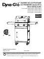
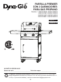
2 BURNER PREMIER
PROPANE GAS GRILL
Model # DGP321SNP / DGP321SNP-D
DGP321CNP / DGP321CNP-D
DGP321GNP / DGP321GNP-D
DGP321MNP / DGP321MNP-D
ATTACH YOUR RECEIPT HERE
Serial Number _____________________________ Purchase Date ______________________
Questions, problems, missing parts? Before returning to your retailer, call our customer
service department at 1-877-447-4768, 8:00 a.m. – 4:30 p.m., CST, Monday – Friday or
e-mail us at [email protected].
Français p. 32
Español p. 63

2
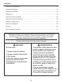
TABLE OF CONTENTS
Safety Information ...................................................................................................................... 3
Package Contents ...................................................................................................................... 5
Hardware Contents .................................................................................................................... 6
Preparation ................................................................................................................................. 6
Assembly Instructions ................................................................................................................ 7
Operation Instructions ................................................................................................................. 18
Care and Maintenance ................................................................................................................. 23
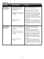
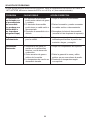
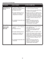
Troubleshooting ........................................................................................................................... 26
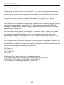
Warranty ...................................................................................................................................... 28
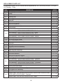
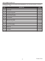
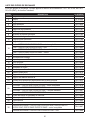
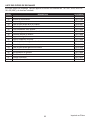
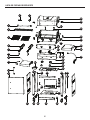
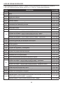
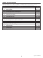
Replacement Parts List .............................................................................................................. 29
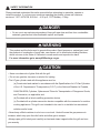
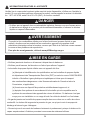
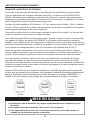
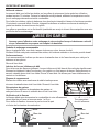
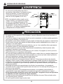
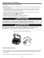
If you smell gas:
1. Shut off gas to the appliance.
2. Extinguish any open ame.
3. Open lid.
4. If odor continues, keep away from
the appliance and immediately call your
local re department.
1. Do not store or use gasoline or
other ammable liquids or vapors
in the vicinity of this or any other
appliance.
2. An LP (liquid propane) cylinder not
connected for use shall not be stored
in the vicinity of this or any other
appliance.
3. This grill is for outdoor use only
and shall not be used in a building,
garage, under overhangs or any other
enclosed area.
4. Do not leave a lit grill unattended.
Keep children and pets away from the
grill at all times.
WARNING
DANGER
Assembler/Installer: This manual contains important information necessary for the proper
assembly and safe use of this appliance. Read and follow all warnings and instructions before
assembling and using this appliance. Leave these instructions with the consumer.
Consumer/User: Follow all warnings and instructions when using this appliance.
Retain these instructions for future reference.

3
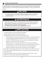
DANGER
CAUTION
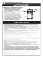
• Do not use in an explosive atmosphere. Keep grill area clear and free from combustible
materials, gasoline and other ammable vapors and liquids.
Please read and understand this entire manual before attempting to assemble, operate or
install the product. If you have any questions regarding the product, please call customer
service at: 1-877-447-4768, 8:00 a.m. – 4:30 p.m., CST, Monday – Friday.
• Never use charcoal or lighter uid with the grill.
• Do not use gasoline, kerosene or alcohol for lighting.
• The LP gas cylinder used with this appliance must be:
(a) Constructed and marked in accordance with the Specications for LP-Gas Cylinders
of the U.S. Department of Transportation (D.O.T.) or the National Standard of Canada,
CAN/CSA-B339, Cylinders, Spheres and Tubes for Transportation of Dangerous Goods;
and Commision, as applicable; and
(b) Provided with a listed overlling prevention device.
(c) Provided with a cylinder connection device compatible with the connector for outdoor
cooking appliances. This grill is not intended to be used in or installed on recreational
vehicles and/or boats.
• Never keep a lled container in a hot car or car trunk. Heat will cause the gas pressure to
increase, which may open the relief valve and allow gas to escape.
• Always open grill lid slowly and carefully as heat and steam trapped within the grill can burn
you severely.
SAFETY INFORMATION
This product and the fuels used to operate this product (liquid propane or natural gas), and
the products of combustion of such fuels, can expose you to chemicals including benzene,
which is known to the State of California to cause cancer and reproductive harm.
For more information go to www.p65Warnings.ca.gov
WARNING

4
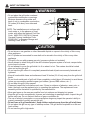
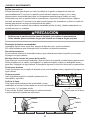
SAFETY INFORMATION
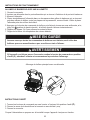
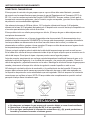
• Do not place the grill under overhead
combustible construction or awnings.
Minimum clearance from sides and
back of unit to combustible construction,
36 inches (914.4mm) from sides and
back.
NOTE: The installation must conform with
local codes or, in the absence of local
codes, with either the National Fuel Gas
Code, ANSI Z223.1/NFPA 54, Natural
Gas and Propane Installation Code,
CSA B149.1, or Propane Storage and
Handling Code, B149.2.
• Do not store or use gasoline or other ammable liquids or vapors in the vicinity of this or any
other appliance.
• An LP cylinder not connected for use shall not be stored in the vicinity of this or any other
appliance.
• This grill is for use with propane gas only (propane cylinder not included).
• Never attempt to attach this grill to the self-contained propane system of a boat, camper trailer,
motor home or house.
• Do not attempt to move the grill while it is lit or when it is hot. The casters should be locked
when not moving the grill.
• Do not use the grill unless it is completely assembled and all parts are securely fastened and
tightened.
• Keep all combustible items and surfaces at least 36 inches (91.44 cm) away from the grill at all
times.
• Do not touch metal parts of grill until it has completely cooled (about 45 minutes) to avoid burns,
unless you are wearing protective gear (pot holders, gloves, BBQ mittens, etc…).
• Do not alter this grill in any manner.
• Clean and inspect the hose before each use. If there is evidence of abrasion, wear, cuts, or
leaks, the hose must be replaced prior to operating the appliance. The replacement hose
assembly will be that which is specied by the manufacturer.
• Move gas hoses as far away as possible from hot surfaces and dripping hot grease.
• Keep the grill’s valve compartment, burners and circulating air passages clean. Inspect the grill
before each use. Do not obstruct the ow of gas or ventilation air.
• The use of alcohol, prescription or non-prescription drugs may impair the operator’s ability to
properly assemble or safely operate the grill.
• Do not leave a lit grill unattended. Keep children and pets away from the grill at all times.
• Do not place this grill on any type of tabletop surface. The grill should be placed on a at and
level surface.
• Do not use the grill in high winds.
WARNING
36in
36in
914.4mm
914.4mm
CAUTION

5
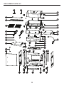
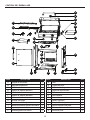
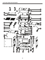
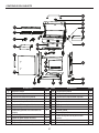
PACKAGE CONTENTS
M
U
V
W
X
D
A
B
C
E
F
G
H
I
N
O
P
Q
R
T
S
K
J
L
B
C
D
A
H
G
E
F
I
JK
L
N
O
M
P
Q
R
V
T
S
U
W
X
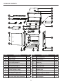
PART DESCRIPTION QTY
A Hood Handle 1
B Temp Gauge 1
C Grill Body Assembly 1
D Side Shelf Bracket A 2
E Right Side Shelf Assembly 1
F Side Shelf Bracket B 2
G Cart Right Side Panel Assembly 1
H Locking Swivel Caster 2
I Non-Locking Swivel Caster 2
J Cart Bottom Panel Shelf 1
K Bottom Panel Skirt Assembly 1
L Cart Left Side Panel Assembly 1
PART DESCRIPTION QTY
M Door Assembly 1
N Door Handle 1
O Left Side Shelf Assembly 1
P Heat Tent 2
Q Cooking Grate 2
R Warming Rack 1
S Control Knob 2
T Grease Pan 1
U Grease Cup 1
V Upper Front Door Brace 1
W Cart Rear Panel 1
X Door Magnet 2

6
AA
BB
DD
CC
M6
Plain
Qty. 2
M6
Qty. 2
M6x16
Bolt
Qty. 18
Washer
EE
M6x35
Bolt
Qty. 4
Washer
FF
M6
Wing Nut
Qty. 2
GG
M3x10
Bolt
Qty. 4
HH
M6x12
Flat Bolt
Qty. 8
Shoulder
Bolt
Qty.4
II
Qty. 1
Wrench
Spring
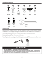
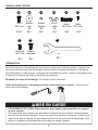
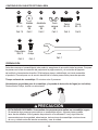
HARDWARE CONTENTS
PREPARATION
Before beginning assembly of product, make sure all parts are present. Compare parts with package
contents list on previous page and hardware contents above. If any part is missing or damaged, do
not attempt to assemble the product. Contact customer service for replacement parts.
Estimated Assembly Time: 50 minutes with 2 people.
Tools Required for Assembly and Leak Testing (not included): Phillips screwdriver, Spray bottle
THIS UNIT IS HEAVY. Two people required for safe assembly.
Two people required for safe assembly. Some parts may contain sharp edges. Wear protective
gloves if necessary. Read and follow all safety statements, warnings, assembly instructions and
use and care instructions before attempting to assemble and use.
CC
AA
BB DD FF
GG
EE
HH II
CAUTION

7
J
AA
G
L
AA
M6x16
Bolt x4
AA
Hardware Used
L
Wrench
x1
II
Hardware Used
G
I
H
II
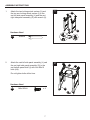
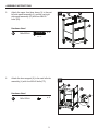
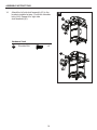
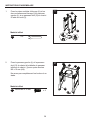
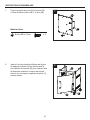
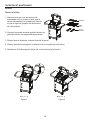
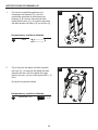
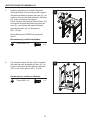
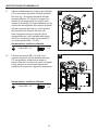
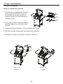
ASSEMBLY INSTRUCTIONS
1. Attach the two locking swivel casters (H) and
the two non-locking swivel casters (I) to the
cart left side panel assembly (L) and the cart
right side panel assembly (G) with wrench (II).
Hardware Used
Wrench
2. Attach the cart left side panel assembly (L) and
the cart right side panel assembly (G) to the
cart bottom panel shelf (J) with four M6x16
bolts (AA).
Do not tighten bolts at this time.
Hardware Used
AA
M6x16 Bolt
x 4
2
II
1
H
I
L
II
G
AA
J
G
L
AA
BB
DD
CC
M6
Plain
Qty. 2
M6
Qty. 2
M6x16
Bolt
Qty. 18
Washer
EE
M6x35
Bolt
Qty. 4
Washer
FF
M6
Wing Nut
Qty. 2
GG
M3x10
Bolt
Qty. 4
HH
M6x12
Flat Bolt
Qty. 8
Shoulder
Bolt
Qty.4
II
Qty. 1
Wrench
Spring

8
AA
W
L
G
AA
M6x16
Bolt x4
AA
Hardware Used
L
G
AA
K
K
G
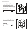
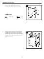
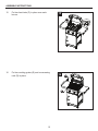
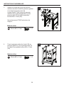
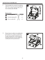
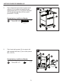
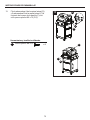
ASSEMBLY INSTRUCTIONS
3. Insert the hook on the bottom panel skirt
assembly (K) into the slot on the cart left side
panel assembly (L) and the cart right side
panel assembly (G) as shown. Attach the
bottom panel skirt assembly (K) to the cart left
side panel assembly (L) and the cart right side
panel assembly (G) with two M6x16 bolts (AA).
Tighten ALL bolts from step 2 securely.
Hardware Used
4. Attach the cart rear panel (W) to the cart left
side panel assembly (L) and the cart right side
panel assembly (G) with the four M6x16 bolts
(AA).
3
4
AA
AA
W
L G
L
K
K
G
G
Hardware Used
AA
AA
M6x16 Bolt
M6x16 Bolt
x 2
x 4
AA
BB
DD
CC
M6
Plain
Qty. 2
M6
Qty. 2
M6x16
Bolt
Qty. 18
Washer
EE
M6x35
Bolt
Qty. 4
Washer
FF
M6
Wing Nut
Qty. 2
GG
M3x10
Bolt
Qty. 4
HH
M6x12
Flat Bolt
Qty. 8
Shoulder
Bolt
Qty.4
II
Qty. 1
Wrench
Spring
AA
BB
DD
CC
M6
Plain
Qty. 2
M6
Qty. 2
M6x16
Bolt
Qty. 18
Washer
EE
M6x35
Bolt
Qty. 4
Washer
FF
M6
Wing Nut
Qty. 2
GG
M3x10
Bolt
Qty. 4
HH
M6x12
Flat Bolt
Qty. 8
Shoulder
Bolt
Qty.4
II
Qty. 1
Wrench
Spring

9
X
FF
G
L
Hardware Used
FF
M3x10
Bolt
x4
V
EE
G
L
M6x35
Bolt x4
EE
Hardware Used
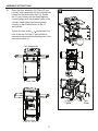
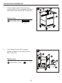
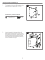
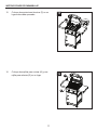
ASSEMBLY INSTRUCTIONS
5. Attach the upper front door brace (V) to the cart
left side panel assembly (L) and the cart right
side panel assembly (G) with four M6x35
bolts (EE).
6. Attach the door magnet (X) to the cart left side
assembly (L) with four M3x10 bolts (FF).
5
6
Hardware Used
EE
M6x35 Bolt
x 4
G
EE
V
L
Hardware Used
FF
M3x10 Bolt
x 4
L
G
FF
X
AA
BB
DD
CC
M6
Plain
Qty. 2
M6
Qty. 2
M6x16
Bolt
Qty. 18
Washer
EE
M6x35
Bolt
Qty. 4
Washer
FF
M6
Wing Nut
Qty. 2
GG
M3x10
Bolt
Qty. 4
HH
M6x12
Flat Bolt
Qty. 8
Shoulder
Bolt
Qty.4
II
Qty. 1
Wrench
Spring
AA
BB
DD
CC
M6
Plain
Qty. 2
M6
Qty. 2
M6x16
Bolt
Qty. 18
Washer
EE
M6x35
Bolt
Qty. 4
Washer
FF
M6
Wing Nut
Qty. 2
GG
M3x10
Bolt
Qty. 4
HH
M6x12
Flat Bolt
Qty. 8
Shoulder
Bolt
Qty.4
II
Qty. 1
Wrench
Spring

10
V
M
K
M
N
AA
AA
M6x16
Bolt x2
AA
Hardware Used
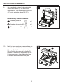
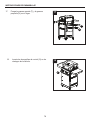
ASSEMBLY INSTRUCTIONS
8. Insert the bottom hinge pin of the cart bottom
panel skirt (K) into the lower hole on the door
assembly (M), then press the upper door spring
hinge pin into the hole on the upper front door
brace (V) as shown.
7. Attach the door handle (N) to the door
assembly (M) with two M6x16 bolts (AA).
7
8
Hardware Used
AA
N
M
V
K
M
AA
M6x16 Bolt
x 2
AA
BB
DD
CC
M6
Plain
Qty. 2
M6
Qty. 2
M6x16
Bolt
Qty. 18
Washer
EE
M6x35
Bolt
Qty. 4
Washer
FF
M6
Wing Nut
Qty. 2
GG
M3x10
Bolt
Qty. 4
HH
M6x12
Flat Bolt
Qty. 8
Shoulder
Bolt
Qty.4
II
Qty. 1
Wrench
Spring

11
B
CC
BB
A
C
DD
Hardware Used
CC
BB
M6
M6
Washer
x2
x2
DD
M6
Wing Nut
x2
Spring
Washer
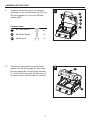
ASSEMBLY INSTRUCTIONS
9. Attach the hood handle (A) to the grill body
assembly (C) with two M6 wing nuts (DD), two
M6 spring washers (CC) and two M6 plain
washers (BB).
9
10. Remove pre-assembled wing nut and plain
washer from the temp gauge (B), then attach
the temp gauge (B) to the grill body assembly
(C). Secure the temp gauge (B) with wing nut
and plain washer removed earlier in this step.
10
Hardware Used
DD
M6 Wing Nut
x 2
BB
M6 Spring Washer
x 2
CC
M6 Plain Washer
x 2
DD
A
C
CC
BB
B
C

12
AA
M6x16
Bolt x2
AA
Hardware Used
G
5mm
AA
AA
M6x16
Bolt x4
AA
Hardware Used
C
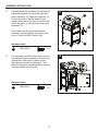
ASSEMBLY INSTRUCTIONS
11. Carefully place the grill body (C) onto cart left
side panel assembly (L) and cart right side
panel assembly (G). Adjust the grill body (C)
so that the holes in the grill body (C) are
aligned with holes in the tabs of cart left side
panel assembly (L) and cart right side panel
assembly (G).
Note: Make sure the gas hose/regulator
assembly is inside the cart. Secure the grill
body (C) with four M6X16 bolts (AA).
11
Hardware Used
AA
M6x16 Bolt
M6x16 Bolt
x 4
C
G
AA
12. Pre-assemble two M6x16 bolts (AA) onto the
cart right side panel assembly (G) and do not
tighten them. Make sure to leave a 5mm
gap between the bolt and the panel. Then
hang the regulator assembly bracket onto the
bolts and tighten the two bolts.
12
Hardware Used
AA
x 2
G
AA
BB
DD
CC
M6
Plain
Qty. 2
M6
Qty. 2
M6x16
Bolt
Qty. 18
Washer
EE
M6x35
Bolt
Qty. 4
Washer
FF
M6
Wing Nut
Qty. 2
GG
M3x10
Bolt
Qty. 4
HH
M6x12
Flat Bolt
Qty. 8
Shoulder
Bolt
Qty.4
II
Qty. 1
Wrench
Spring
AA
BB
DD
CC
M6
Plain
Qty. 2
M6
Qty. 2
M6x16
Bolt
Qty. 18
Washer
EE
M6x35
Bolt
Qty. 4
Washer
FF
M6
Wing Nut
Qty. 2
GG
M3x10
Bolt
Qty. 4
HH
M6x12
Flat Bolt
Qty. 8
Shoulder
Bolt
Qty.4
II
Qty. 1
Wrench
Spring

13
GG
F
D
F
D
Hardware Used
GG
M6x10
Flat Bolt
x8
13
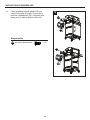
ASSEMBLY INSTRUCTIONS
13. Attach the side shelf bracket A (D) and side
shelf bracket B (F) to the grill body assembly
(C) with eight M6x12 at bolts (GG).
D
F
F
GG
Hardware Used
GG
M6x12 Flat Bolt
x 8
AA
BB
DD
CC
M6
Plain
Qty. 2
M6
Qty. 2
M6x16
Bolt
Qty. 18
Washer
EE
M6x35
Bolt
Qty. 4
Washer
FF
M6
Wing Nut
Qty. 2
GG
M3x10
Bolt
Qty. 4
HH
M6x12
Flat Bolt
Qty. 8
Shoulder
Bolt
Qty.4
II
Qty. 1
Wrench
Spring
D
C
C

14
HH
HH
E
O
Hardware Used
HH
Shoulder
Bolt
x4
14
ASSEMBLY INSTRUCTIONS
14. Attach the left side shelf assembly (O) to the
brackets installed at step 13 with two shoulder
bolts (HH). Repeat it for right side
shelf assembly (E).
Hardware Used
HH
Shoulder Bolt
x 4
HH
HH
O
E
AA
BB
DD
CC
M6
Plain
Qty. 2
M6
Qty. 2
M6x16
Bolt
Qty. 18
Washer
EE
M6x35
Bolt
Qty. 4
Washer
FF
M6
Wing Nut
Qty. 2
GG
M3x10
Bolt
Qty. 4
HH
M6x12
Flat Bolt
Qty. 8
Shoulder
Bolt
Qty.4
II
Qty. 1
Wrench
Spring

15
Q
R
P
ASSEMBLY INSTRUCTIONS
15. Put two heat tents (P) in place over each
burner.
15
P
R
Q
16. Put two cooking grates (Q) and one warming
rack (R) in place.
16

16
S
T
U
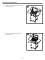
ASSEMBLY INSTRUCTIONS
17. Put the grease pan (T) and grease cup (U) into
place.
17
18. Assemble the two control knobs (S) to the
valve stems.
18
T
U
S

17
LP Gas
Cylinder
Tank
Screw
Front View
Rear View
Front View
Rear View
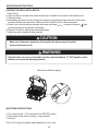
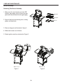
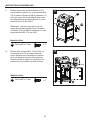
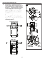
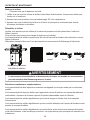
ASSEMBLY INSTRUCTIONS
19. Open the door assembly (M). Place LP gas
cylinder (sold separately) into the nesting hole
located on the cart bottom shelf (J). Rotate
the LP gas cylinder until the hose/regulator
coupling aligns with the threaded valve of the
cylinder. Hand tighten the hose/regulator
coupling to the threaded valve of the LP
gas cylinder.
Tighten the tank screw clockwise in the
rear of the cart until the LP gas cylinder is
secured in place inside the nesting hole of the
cart bottom shelf (J).
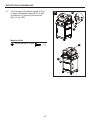
19
Front View
Rear View
Fully Assembled
M
J

18
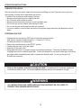
OPERATION INSTRUCTIONS
CHECKING FOR LEAKS
After all connections are made, check all connections and ttings on the LP gas tank valve, gas hose
and regulator for leaks with a water and soap solution.
To prevent re or explosion while testing for a leak:
• Always perform leak test prior to lighting the grill.
• Do not smoke while testing for a leak.
• Always perform leak tests outdoors in a well-ventilated area.
• Do not use any source of ame while testing for leaks.
• Do not use the grill until any and all leaks are corrected.
• If you are unable to correct a leak, disconnect the propane supply and call a gas appliance service
dealer.
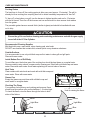
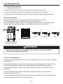
PERFORM LEAK TEST
• Prepare leak test solution by 50/50 ratio of liquid dish soap and water.
Total solution required is approximately 2 - 3 ounces (70 - 90 ml).
Put leak test solution in a spray bottle.
• Ensure all control knobs are in the
O OFF position.
• Connect the gas hose to the gas supply.
• Open the LP gas tank valve.
• Spray leak test solution on all gas carrying connections and ttings. Presence of bubbles at areas
of applied test solution indicates a gas leak. If leaks are detected or you smell or hear gas, shut off the
gas supply valve immediately and repair or replace the defective part. Do not use the grill until
all leaks are corrected.
ALL INSTRUCTIONS AND SAFEGUARDS ON THIS PAGE MUST BE FOLLOWED TO
PREVENT FIRE, DAMAGE AND/OR INJURY.
Only use the regulator and hose assembly provided! If a replacement is necessary, please call
our customer service center. Do not use replacement parts that are not intended for this grill.
WARNING
CAUTION

19
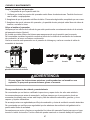
OPERATION INSTRUCTIONS
CONNECTING GAS CYLINDER
The propane gas supply cylinder to be used must be constructed and marked in accordance with the
Specications for LP Gas Cylinders of the U.S. Department of Transportation (D.O.T.) or the National
Standard of Canada, CAN/CSA-B339, Cylinders, Spheres and Tubes for Transportation of Dangerous
Goods; and Commission, as applicable; and provided with a listed overlling prevention device.
Use only 20-pound cylinders (height: 18.11 inches, tank diameter: 9.84 inches, foot diameter: 8.03 inches)
equipped with a cylinder connection device compatible with the connection for outdoor cooking appli-
ances.
The cylinder must include a collar to protect the cylinder valve. The gas cylinder should not be dropped
or handled roughly!
If the appliance is not in use, the gas cylinder must be disconnected. Storage of an appliance indoors
is permissible ONLY if the cylinder is disconnected and removed from the appliance. Cylinders must
be stored outdoors out of the reach of children and must not be stored in a building, garage or any
other enclosed area. Your cylinder must never be stored where temperatures can reach over 125°F.
Place dust cap on cylinder valve outlet whenever the cylinder is not in use. Only install the type of
dust cap on the cylinder valve outlet that is provided with the cylinder valve. Other types of caps or
plugs may result in leakage of propane.
Before connection, be sure that there is no debris caught in the outlet of the gas cylinder, outlet of the
regulator valve or in the outlet of the burner and burner ports. Connect regulator valve and
hand-tighten rmly. Keep the propane cylinder valve closed and disconnect the propane cylinder from
the regulator valve when the grill is not in use.
DO NOT obstruct the ow of combustion air and ventilation air to the grill. The propane cylinder must
be arranged for vapor withdrawal and equipped with a listed overlling prevention device. Please use
the proper cylinder orientation to provide vapor withdrawal. NOTE: The cylinder must be fully upright
for the cylinder to have vapor withdrawal only.
a. Do not store a spare LP-gas cylinder under or near this appliance.
b. Never ll the cylinder beyond 80 percent full.
c. If the information in (a) and (b) is not followed exactly, a re causing death or serious
injury may occur.
CAUTION

20
OPERATION INSTRUCTIONS
NOTE: Other cylinders may be acceptable for use with this appliance provided they are compatible
with the appliance nesting hole and retention means. Refer to Step 19 of the Assembly Instructions
for correct cylinder to cylinder holder connection.
ALL INSTRUCTIONS AND SAFEGUARDS ON THIS PAGE MUST BE FOLLOWED TO
PREVENT FIRE, DAMAGE AND/OR INJURY.
In the connection process, make sure:
• the regulator inlet connector mates with the cylinder valve outlet properly, safely and rmly, and;
• the LP gas hose does not come in contact or remain in contact with the rebox.
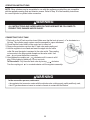
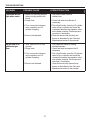
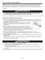
CONNECTING THE LP TANK
1. The knob on the LP tank must be closed. Make sure that the knob is turned clockwise to a
full stop. The cylinder supply system must be arranged for vapor withdrawal.
2. Check that the control knob on the control unit is turned off.
3. Remove the protective cap from the LP tank valve and coupling nut.
4. Hold the regulator in one hand and insert the nipple into the valve
outlet. Be sure the nipple is centered in the valve outlet. The coupling
nut connects to the large outside threads on the valve outlet. Use
care – do not cross thread the connection.
5. Hand-tighten the coupling nut clockwise until it comes to a full
stop. Firmly tighten by hand only. Do not use tools.
To Disconnect: Fully close the tank valve by turning clockwise.
Turn the coupling nut counterclockwise until the regulator assembly detaches.
WARNING
WARNING
La page est en cours de chargement...
La page est en cours de chargement...
La page est en cours de chargement...
La page est en cours de chargement...
La page est en cours de chargement...
La page est en cours de chargement...
La page est en cours de chargement...
La page est en cours de chargement...
La page est en cours de chargement...
La page est en cours de chargement...
La page est en cours de chargement...
La page est en cours de chargement...
La page est en cours de chargement...
La page est en cours de chargement...
La page est en cours de chargement...
La page est en cours de chargement...
La page est en cours de chargement...
La page est en cours de chargement...
La page est en cours de chargement...
La page est en cours de chargement...
La page est en cours de chargement...
La page est en cours de chargement...
La page est en cours de chargement...
La page est en cours de chargement...
La page est en cours de chargement...
La page est en cours de chargement...
La page est en cours de chargement...
La page est en cours de chargement...
La page est en cours de chargement...
La page est en cours de chargement...
La page est en cours de chargement...
La page est en cours de chargement...
La page est en cours de chargement...
La page est en cours de chargement...
La page est en cours de chargement...
La page est en cours de chargement...
La page est en cours de chargement...
La page est en cours de chargement...
La page est en cours de chargement...
La page est en cours de chargement...
La page est en cours de chargement...
La page est en cours de chargement...
La page est en cours de chargement...
La page est en cours de chargement...
La page est en cours de chargement...
La page est en cours de chargement...
La page est en cours de chargement...
La page est en cours de chargement...
La page est en cours de chargement...
La page est en cours de chargement...
La page est en cours de chargement...
La page est en cours de chargement...
La page est en cours de chargement...
La page est en cours de chargement...
La page est en cours de chargement...
La page est en cours de chargement...
La page est en cours de chargement...
La page est en cours de chargement...
La page est en cours de chargement...
La page est en cours de chargement...
La page est en cours de chargement...
La page est en cours de chargement...
La page est en cours de chargement...
La page est en cours de chargement...
La page est en cours de chargement...
La page est en cours de chargement...
La page est en cours de chargement...
La page est en cours de chargement...
La page est en cours de chargement...
La page est en cours de chargement...
La page est en cours de chargement...
La page est en cours de chargement...
La page est en cours de chargement...
-
 1
1
-
 2
2
-
 3
3
-
 4
4
-
 5
5
-
 6
6
-
 7
7
-
 8
8
-
 9
9
-
 10
10
-
 11
11
-
 12
12
-
 13
13
-
 14
14
-
 15
15
-
 16
16
-
 17
17
-
 18
18
-
 19
19
-
 20
20
-
 21
21
-
 22
22
-
 23
23
-
 24
24
-
 25
25
-
 26
26
-
 27
27
-
 28
28
-
 29
29
-
 30
30
-
 31
31
-
 32
32
-
 33
33
-
 34
34
-
 35
35
-
 36
36
-
 37
37
-
 38
38
-
 39
39
-
 40
40
-
 41
41
-
 42
42
-
 43
43
-
 44
44
-
 45
45
-
 46
46
-
 47
47
-
 48
48
-
 49
49
-
 50
50
-
 51
51
-
 52
52
-
 53
53
-
 54
54
-
 55
55
-
 56
56
-
 57
57
-
 58
58
-
 59
59
-
 60
60
-
 61
61
-
 62
62
-
 63
63
-
 64
64
-
 65
65
-
 66
66
-
 67
67
-
 68
68
-
 69
69
-
 70
70
-
 71
71
-
 72
72
-
 73
73
-
 74
74
-
 75
75
-
 76
76
-
 77
77
-
 78
78
-
 79
79
-
 80
80
-
 81
81
-
 82
82
-
 83
83
-
 84
84
-
 85
85
-
 86
86
-
 87
87
-
 88
88
-
 89
89
-
 90
90
-
 91
91
-
 92
92
-
 93
93


Dyna-Glo DGP321CNP-D Manuel utilisateur
- Catégorie
- Barbecues
- Taper
- Manuel utilisateur
- Ce manuel convient également à
dans d''autres langues
- English: Dyna-Glo DGP321CNP-D User manual
- español: Dyna-Glo DGP321CNP-D Manual de usuario
Documents connexes
-
Dyna-Glo DGP321CNP-D Manuel utilisateur
-
-
Dyna-Glo Dyna-Glo DG13GT-D Stainless Steel Grill Topper Manuel utilisateur
-
Dyna-Glo DGF493BNP Le manuel du propriétaire
-
-
-
-
-
-


