
Swing check valve
Clapet à battant
Válvula de clapeta
Características
Presión de servicio a 20°C (73°F) temperatura de
agua:
- D75 - D140 (2½” - 5”) PN 10 bar (150 p.s.i.)
- D160 - D225 (6” - 8”) PN 6 bar (90 p.s.i.)
Characteristics
Working pressure at 20°C (73°F) water temperature:
- D75 - D140 (2½” - 5”) PN 10 bar (150 p.s.i.)
- D160 - D225 (6” - 8”) PN 6 bar (90 p.s.i.)
Caractéristiques
Pression de service à 20°C (73°F) température de
l`eau:
- D75 - D140 (2½” - 5”) PN 10 bar (150 p.s.i.)
- D160 - D225 (6” - 8”) PN 6 bar (90 p.s.i.)
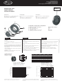
Description / /
1. Body / Corps / Cuerpo PVC-U
2. Flap / Clapet battant / Clapeta PVC-U
3. Cap / Bouchon / Tapón PP
4. Body O-Ring / Joint de corps / Junta cuerpo EPDM / FPM
5. Flap O-Ring / Joint battant / Junta clapeta EPDM / FPM
Description Descripción Material / Matière / Material
Components / Composants / Componentes
Installation
Install with flanges and PN 10 pipe.
Do not install the valve at a distance lower than 5 x D of the
pump out.
The valve must be installed in vertical or horizontal pipework.
On horizontal pipework the flange hinge must be at the top.
Ensure the direction of flow is in accordance with the arrow
on the valve body.
Use the centralising screw to ensure the valve is positioned
centrally in the flanges.
WARNING: To ensure the valves work correctly, the stub
flanges must be perfectly lined up.
Montage
Montage réalisé à l’aide de brides norme DIN et tubes PVC
pression PN 10.
Ne pas installer la vanne à moins de 5 x D de la sortie d’une
pompe.
En position verticale, respecter scrupuleusement le sens
d’ouverture du volet du bas vers le haut.
En position horizontale, le repère soit obligatoirement être
positionné en partie supérieure de la tuyauterie.
ATTENTION: pour une utilisation correcte du clapet à battant
respecter l’alignement des brides avec le clapet.
Montaje
Montar con bridas s/DIN y tubos para presión nominal PN 10.
No montar la válvula a una distancia inferior a 5 x D de la
salida de una bomba.
Montar con el tubo en posición vertical con el sentido del
fluido hacia arriba o bien horizontal con el tornillo de centraje
en la parte superior de la válvula.
ATENCION: para su correcto funcionamiento alinear
perfectamente la válvula con los manguitos portabridas.
• WE RESERVE THE RIGHT TO CHANGE ALL OR PART OF THE FEATURES OF THE
ARTICLES OR CONTENTS OF THIS DOCUMENT, WITHOUT PRIOR NOTICE.
• NOUS NOUS RÉSERVONS LE DROIT DE MODIFIER TOTALEMENT OU EN PARTIE
LES CARACTERISTIQUES DE NOS ARTICLES OU LE CONTENU DE CE DOCUMENT
SANS PRÉ-AVIS.
• NOS RESERVAMOS EL DERECHO DE CAMBIAR TOTAL O PARCIALMENTE LAS
CARACTERISTICAS DE NUESTROS ARTICULOS O CONTENIDO DE ESTE DOCUMENTO
SIN PREVIO AVISO.
ENGLISH FRANÇAIS ESPAÑOL
EDITION: 12 - 2006
C
H
M
E
L
D
D C H E M x L
mm “ mm “ mm “ mm “ mm “
75 / 2 ½” 40 1.57 20 0.79 129 5.08 16x120 0.63x4.72
90 / 3” 52 2.05 20 0.79 144 5.67 16x120 0.63x4.72
110 / 4” 70 2.76 22 0.87 164 6.46 16x120 0.63x4.72
125 / 4 ½” 83 3.27 25 0.98 170 6.69 16x130 0.63x5.12
140 / 5” 92 3.62 24 0.94 195 7.68 16x130 0.63x5.12
160 / 6” 112 4.41 26 1.02 220 8.66 20x160 0.79x6.30
200 / 7” 139 5.47 28 1.10 247 9.72 20x160 0.79x6.30
225 / 8” 150 5.91 34 1.34 275 10.83 20x160 0.79x6.30
0
1
2
3
16
17
18
15
14
13
12
11
10
9
8
7
4
5
6
bar
20
30
40
50 60 70 80 90 100 10
°C
0
68
86
104
122 140 158
176
194
212 50
°F
32
0
15
30
45
240
255
270
225
210
195
180
165
150
135
120
105
60
75
90
p.s.i.
20 years / water flow
20 années / fluide de l’eau
20 años / fluido agua
Pressure / Pression / Presión
Temperature / Température / Temperatura
Pressure / temperature graph
Diagramme pression / température
Diagrama presión / temperatura
PN 10
PN 6
Pressure loss diagram
Diagramme de perte de charge
Diagrama de pérdidas de carga
10
5,88
100
58,8
1.000
588
m³/h
ft³/min
0,01
0,15
0,1
1,5
1
15
bar
p.s.i.
-
2
D
75
½
”
D9 - 3
0 ”
D 0
-
”
1
1 4
D
1 5
-
4
½”2
”D
1
40
-
5
0
”D
1
6
-6
D
2
00
-
7
”
D
2
25
- 8
”
Flow / Débit / Caudal
Pressure loss / Perte de charge / Pérdida de carga
Installation with flanges
Montage avec brides
Instalación con bridas
Dwyer Instruments Inc.
P.O. Box 373, 102 Indiana Hwy. 212
Michigan City, IN 46361 USA
Tel. 219/879-8000 - Fax 219/872-9057
E-mail: [email protected] - Website: www.dwyer-inst.com
R
Fpv-1
-
 1
1

dans d''autres langues
- English: Dwyer Series FPV User manual
- español: Dwyer Series FPV Manual de usuario