
DigiDish 33
DigiDish 45
Satman 33
Satman 45
für Wandmontage
Montageanleitung
D EE NF R
E SI TN O
D K
S V
F IP L
C ZH U
N LE L
DIGIDISH 33
DIGIDISH 45
SATMAN 33
SATMAN 45

Sehr geehrter Kunde,
Sie haben sich für ein Qualitätsprodukt der Firma TechniSat entschieden. Um die Qualität
des Produktes über Jahre hinweg zu erhalten, bestehen Halterung und Spiegel aus
Aluminium.
Der Spiegel ist zum Empfang der digitalen Signale der ASTRA-Satelliten konzipiert. Lesen
Sie bitte vor der Montage sorgfältig die Montageanleitung, damit Sie nach der Installation die
optimalen Empfangse
igenschaften erreichen.
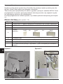
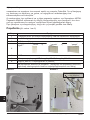
Bevor Sie mit der Montage beginnen, überprüfen Sie die Lieferung der Außeneinheit auf
Vollständigkeit.
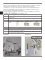
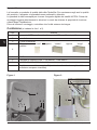
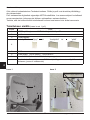
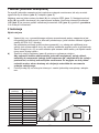
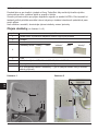
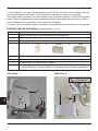
Lieferumfang (siehe Abbildung 1 und 2)
2
D E
1
A
A
2
3
4
B
C
5
6
D Schrauben zur Einstellung
des Elevationswinkels
Abbildung 1
Abbildung 2
Pos. Artikel
1 1 AZ/EL-Halterung mit LNB-Halteschelle und Schwenkprofil
2 1 Spiegel
3 1 Zwischenstück
4
1 Wandhalter*:
5 1 LNB
6 1 LNB-Halteschelle, 1 Schraube M6x40, 1 Schraube M6x16
A 4 Schrauben M6x15, 4 Muttern M6, 4 Unterlegscheiben
10m Koaxialkabel mit F-Steckern (nur bei Komplettsets inkl. Receiver im
Lieferumfang enthalten)
“kurz” “mittel” “lang”oderoder
* Inhalt abhängig vom gewählten Paket

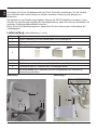
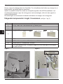
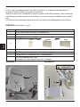
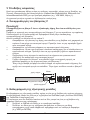
1 Montage der Außeneinheit
Die Außeneinheit ist im Auslieferungszustand teilweise vormontiert, so dass Sie lediglich
den Spiegel (Pos. 2) und das Zwischenstück (Pos. 3) montieren müssen.
Befestigen Sie zunächst den Spiegel mit den Schrauben (A) an der AZ/EL-Halterung
(Pos. 1). Lösen Sie anschließend die Schraube (B) am Schwenkprofil um das
Zwischenstück zu montieren. Montieren Sie anschließend das LNB
(Pos. 5) mit
Hilfe der LNB-Halteschelle (Pos. 6) nach Abbildung 1 an den LNB-Halter.
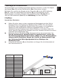
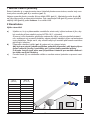
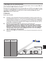
2 Aufbau
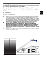
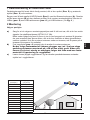
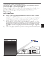
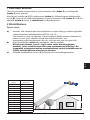
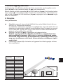
Auswahl des Standortes
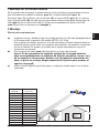
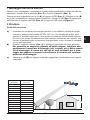
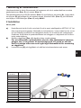
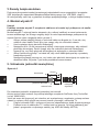
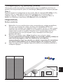
a) Stellen Sie sicher, dass von dem vorgesehenen Montageplatz aus freie Sicht in
Richtung Süden zum Empfang der Satellitenposition ASTRA 19,2° Ost besteht.
Mit Hilfe der unten aufgeführten Graphik können Sie ersehen, ob Sie genügend
Abstand zu einem benachbarten Hindernis eingehalten haben
, um eine
Abschwächung des Empfangs durch dieses Hindernis zu vermeiden. Achten Sie
darauf, dass der Spiegel bei der Montage unter einer Terrasse nicht durch ein hervor-
stehendes Dach abgeschattet wird.
b) Befestigen Sie den Wandhalter (Pos. 4) waagerecht an dem ausgesuchten Ort.
Um der Außeneinheit optimalen Halt zu gewährleisten, sollten Sie
das Befestigungsmaterial (Schrauben, Dübel etc.) der Monta
gefläche
entsprechend auswählen. Wegen der Vielfalt an Mauerwerken liegt
der Lieferung kein Befestigungsmaterial zur Montage des
Wandhalters bei.
c) Lösen Sie die Schraube (C) am Wandhalter und hängen Sie die Außeneinheit mit
dem Zwischenstück ein.
3
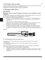
Winkel A
(Elevation)
Steigung B
(cm pro m)
22° 40,40
24° 44,52
26° 48,77
28° 53,17
29° 55,40
30° 57,74
31° 60,00
32° 62,49
33° 64,90
34° 67,45
35° 70,02
36° 72,65
37° 75,36
38° 78,13
D E

4
D E
3 Sicherheitshinweise
Beachten Sie bei der Installation die entsprechenden Europanormen und VDE-
Bestimmungen zur Gewährleistung der elektrischen Sicherheit (z.B. VDE 0855, Teil1).
Befragen Sie dazu ggf. Ihren Fachhändler.
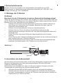
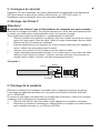
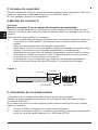
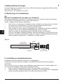
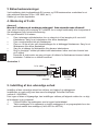
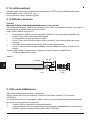
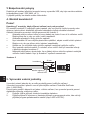
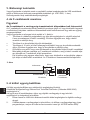
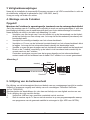
4. Montage der F-Stecker
Achtung!
Montieren Sie die F-Stecker im stromlosen Zustand der Empfangsanlage!
Gehen Sie bei der Montage der F-Stecker sehr sorgfältig vor, damit Funktionsstör
ungen oder
gar die Zerstörung des Satreceivers durch falsche Steckermontage ausgeschlossen werden.
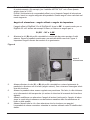
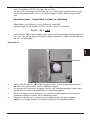
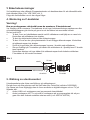
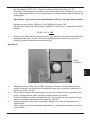
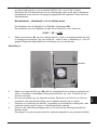
Beachten Sie zu der Textausführung auch Abbildung 3.
> Entfernen Sie die Isolierung des Kabelendes mit Hilfe eines scharfen Messers auf
einer Länge von 6 mm bis auf den Innenleiter. Beachten Sie dabei, dass der
Innenleiter nicht beschädigt wird.
> Entfernen Sie die überstehenden Drähte des Abschirmgeflechts.
> Entfernen Sie nun 10 mm der äußeren Kunststoffummantelung um das
Abschirmgeflecht freizulegen. Beachten Sie, dass das Abschirmgeflecht dabei nicht
beschädigt wird.
> Gehen Sie sicher, dass keine Drähte des Abschirmgeflechts den Innenleiter
berühren.
> Drehen Sie nun den F-Stecker vorsichtig auf das Kabel, bis der Innenleiter bündig mit
dem vorderen Rand des F-Steckers abschließt.
Prüfen Sie abschließend n
och einmal, dass kein Draht des Abschirmgeflechts den
Innenleiter des Kabels berührt. Der F-Stecker ist nun richtig montiert.
5. Ausrichten der Außeneinheit
Die Ausrichtung der Außeneinheit sollte mit Hilfe eines Messgerätes vorgenommen werden.
Ebenso ist die Ausrichtung mit Hilfe eines preisgünstigeren TechniSat SatFinders
(Artikel-Nr. 0000/3045) möglich.
Sollte beides nicht vorhanden sein, kann mit
Hilfe eines digitalen Receivers und eines
Fernsehgeräts die Ausrichtung wie folgt durchgeführt werden.
1. Verbinden Sie das LNB und den Receiver durch ein geeignetes Koaxialkabel.
2. Schließen Sie den Receiver an das Fernsehgerät an und stellen Sie den Receiver
auf einen Programmplatz ein, auf dem ein Programm des gewünschten Satelliten zu
empfangen ist (z.B. ARD für ASTRA).
schraubbarer
F-Stecker
20mm
drahtfrei
Drahtgeflecht
Silberfolie
6
10
Abbildung 3

3. Entnehmen Sie aus der AZ/EL-Tabelle (siehe Kapitel 6) den Elevationswinkel für
Ihren Aufstellungsort. Dieser ist zum Beispiel für den Satelliten ASTRA 19,2° Ost in
Daun 31,29°.
Da es sich bei Ihrer Außeneinheit um einen Offsetspiegel handelt, wird nicht der
abgelesene Elevationswinkel, sondern ein dem Spiegel angepasster Winkel einge-
stellt. Dieser wird wie folgt berechnet:
:
Elevationswinkel - Offset
winkel = Einzustellender Winkel
Der Offsetwinkel des DigiDish 33 bzw. des DigiDish 45 beträgt 30°.
Somit ergibt sich für einen DigiDish 33 bzw. 45 z.B. in Daun ein Winkel von:
31,29° - 30° = 1,29°
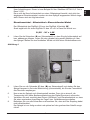
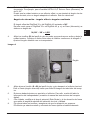
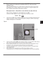
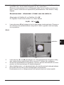
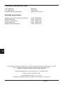
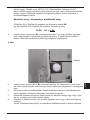
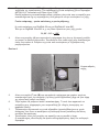
4. Lösen Sie die Schrauben (D) am Schwenkprofil so, dass Sie die Außeneinheit auf-
bzw. abbewegen können. Legen Sie eine gerade Latte gemäß Abbildung 4 über
den Spiegel. Stellen Sie den ermittelten Winkel mit Hilfe eines Winkelmessers ein.
Abbildung 4
5. Lösen Sie nun die Schraube (C) bzw. (B) am Schwenkprofil und drehen Sie den
Spiegel langsam in Ost-oder Westrichtung (Azimutwinkel), bis Sie das Fernsehb
ild
des Receivers empfangen.
6. Nun muss der Spiegel noch feineingestellt werden. Dazu ist es sinnvoll, die
Transponder-Info (siehe Bedienungsanleitung des Digital-Receivers) aufzurufen.
7. Verändern Sie nun vorsichtig den Azimut (Ost/West)- und Elevationswinkel so, dass
Sie einen maximalen Ausschlag der Pegel- bzw. Qualitätsanzeige erhalten.
8. Befestigen Sie nun alle Schrauben und beachten Sie, dass sic
h der Empfang dabei
nicht verschlechtert.
Der Spiegel ist nun fertig montiert und optimal auf den gewünschten Satellit ausge-
richtet.
5
Messlatte
D E

6
D E
180309
Kennwerte des LNBs:
LOF Low-Band: 9750 MHz
LOF High-Band: 10600 MHz
Umschaltung Low - / High-Band: 22kHz-Signal des Receivers
Optionales Zubehör:
An-Rohr-Fitting für die Mastmontage Art.-Nr.: 0000/0500
Balkonständer Art.-Nr.: 0000/1751
Saugfuß-Halterung Art.-Nr.: 0000/1758
Balkonständer Art.-Nr.: 0000/1755
Betonplattenständer Art.-Nr.: 0000/1756
Dieses Produkt trägt das CE-Zeichen und erfüllt alle erforderlichen EU-Normen.
Änderungen und Druckfehler vorbehalten. Stand 06/12
DigiDish und TechniSat sind eingetragene Warenzeichen der
TechniSat Digital GmbH
Postfach 560 - 54541 Daun
www.technisat.com
Hotline: +49 (0) 3925 9220 1806
Montag bis Freitag 8:00 -18:00 Uhr.
(es fallen die regulären Telefongebühren
für die Anrufe aus dem Ausland an)
TechniSat Digital GmbH • Julius-Saxler-Str. 3 • D-54550 Daun
Hotline: +49 (0) 3925 9220 1800

7
E N
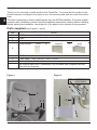
DigiDish 33
DigiDish 45
Satman 33
Satman 45
for mounting on walls
Installation
instructions
DIGIDISH 33
DIGIDISH 45
SATMAN 33
SATMAN 45

8
E N
Dear Customer
Thank you for choosing a quality product from TechniSat. To ensure that the quality of the
product remains unchanged over years of use, the mounting and dish are made from alumi-
nium.
The dish is designed to receive digital signals from the ASTRA satellites. To ensure optimal
reception after installation, please read the installation instructions carefully before installing.
Before sta
rting the installation, check that all of the parts for the external unit are present.
Parts supplied (see Figures 1 and 2)
1
A
A
2
3
4
B
C
5
6
D Screws for setting the
angle of elevation
Figure 1
Figure 2
Item Article
1 1 AZ/EL bracket with LNB clamp and swivel profile
2 1 Dish
3 1 Connector rod
4
1 Wall bracket*:
5 1 LNB
6 1 LNB clamp, 1 M6 x 40 bolt, 1 M6 x 16 bolt
A 4 M6 x 15 bolts, 4 M6 nuts, 4 washers
10m coaxial cable with F-connectors (only included with complete sets that
come with the receiver)
“short” “medium” “long”oror
* Contents depend on package selected

9
E N
1 Assembling the external unit
The external unit is delivered partially pre-assembled. Only the dish (Item 2) and the
connector rod (Item 3) need to be attached.
First, use bolts (A) to attach the dish to the AZ/EL bracket (Item 1). Then loosen screw (B)
on the swivel mount to attach the connector rod. After this, install the LNB (Item 5) on the
LNB bracket using the LNB clamp (Item 6) as shown in Fig
ure 1.
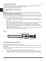
2 Installation
Selecting a location
a) Make sure that there is an uninterrupted line of sight from the location in which you
are planning to install the dish to the southern sky to enable reception from the positi-
on of the ASTRA 19.2° East satellite. You can use the illustration below to verify
whether you have left sufficient distance from any nearby obstruction to prevent the
obstruction from w
eakening signal reception. Make sure when installing beneath a
terrace that the dish is not within the shadow of any protruding roof.
b) Mount the wall bracket (Item 4) horizontally in the location selected.
In order to ensure that the external unit is as securely mounted as
possible, you should select the appropriate mounting hardware (scr-
ews wall plugs, etc.) for the surface onto which the unit is
being
installed. Because of the wide variety of wall types, no wall bracket
mounting hardware is included.
c) Loosen screw (C) on the wall bracket and attach the external unit using the connec-
tor rod.
Angle A
(Elevation)
Gradient B
(cm per m)
22° 40.40
24° 44.52
26° 48.77
28° 53.17
29° 55.40
30° 57.74
31° 60.00
32° 62.49
33° 64.90
34° 67.45
35° 70.02
36° 72.65
37° 75.36
38° 78.13

10
E N
3 Safety instructions
To ensure electrical safety when performing the installation, follow the applicable European
standards and VDE regulations (e.g. VDE 0855, Part 1).
If you are unsure, ask your specialist dealer.
4. Installing the F-connectors
Caution!
Make sure that the receiver equipment is disconnected from the mains
when installing the F-connectors.
Proceed with extreme caution when installing the
F-connectors in order to prevent the satel-
lite receiver from malfunctioning or being damaged irretrievably due to incorrect installation.
In addition to the text, please consult Figure 3.
> Use a sharp knife to strip the insulation from the end of the cable, leaving 6 mm of
the cable core exposed. When stripping the insulation, be sure to avoid damage to
the core.
> Remove the overlying wire shielding
.
> Now remove 10 mm of the outer plastic sheath to expose the wire shielding. When
removing the plastic sheath, be sure to avoid damage to the wire shielding.
> Make sure that none of the wires from the shielding are touching the cable core.
> Now twist the F-connector carefully onto the cable until the core wire is flush with the
front edge of the F-connector.
Finally, check again that none of the wires
from the shielding are touching the cable
core. The F connector is now correctly installed.
5. Pointing the external unit.
The external unit should be pointed using a meter.
It is also possible to point the unit using the less expensive TechiSat SatFinder (article No.
0000/3045).
Should neither of these be available, the dish can be pointed using a digital receiver and a
television as follows.
1. Connec
t the LNB with the receiver using a suitable coaxial cable.
2. Connect the receiver to the television and set the receiver to a programme channel
on which a signal from the desired satellite can be received (e.g. ARD for ASTRA).
Screwable
F-connector
20 mm
Wire-free
Wire shielding
Silver foil
6
10
Figure 3

11
E N
3. Select the angle of elevation for your installation location from the AZ/EL table (see
section 6). For example, in Daun the angle of elevation for the ASTRA 19.2° East
satellite is 31.29°.
Because your external unit has an offset dish, the angle of elevation to be set is not
the one you read from the table, but is rather an adjusted angle for the dish. This is
calculated as follows:
Angle of elevation
minus offset angle = angle to be set.
The offset angle for the DigiDish 33 and the DigiDish 45 is 30°.
Thus, the angle at which the DigiDish 33 and 45 need to be set in Daun is as
follows:
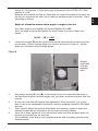
31,29° - 30° = 1,29°
4. Loosen the screws (D) on the swivel mount so that the external unit can be moved
up and down. Place a straight edge over the dish as shown in Figure 4. Set the
angle you calculated using an angle gauge.
Figure 4
5. Now loosen screws (C) and (B) on the swivel mount and rotate the dish slowly in
the East-West direction (azimuth angle) until you obtain a television picture from the
receiver.
6. At this poi
nt, the dish still requires fine adjustment. When doing this, it is a good
idea to call up the transponder information (see the operating manual for the digital
receiver).
7. Then carefully adjust the azimuth (East/West) and elevation angles to obtain the
maximum amplitude as indicated on the the level and quality display.
8. Once this is done, tighten all of the screws and make sure that reception does
not
become worse while you are doing so.
The installation of the dish is now complete and the dish is properly pointed at the
desired satellite.
Straight
edge used
for angle
measure-
ment

12
E N
180309
LNB specifications:
Low-band LOF: 9,750 MHz
High-band LOF: 10,600 MHz
Low/high-band switchover: 22 kHz signal from the receiver
Optional accessories:
Pipe bracket for mounting on a mast Art. No.: 0000/0500
Balcony stands Art. No.: 0000/1751
Suction pad bracket Art. No.: 0000/1758
Balcony stands Art. No.: 0000/1755
Concrete slab stands Art. No.: 0000/1756
This product bears the CE symbol and meets all of the required EU standards
Amendments and printing errors reserved. Last updated: 06/12
DigiDish and TechniSat are registered trademarks of
TechniSat Digital GmbH
Postfach 560 - 54541 Daun
www.technisat.com
+49 (0) 3925 9220 1806
Monday to Friday 08:00 - 18:00
(normal charges will apply for overseas calls)
TechniSat Digital GmbH • Julius-Saxler-Str. 3 • D-54550 Daun
Hotline: +49 (0) 3925 9220 1806

13
F R
DigiDish 33
DigiDish 45
Satman 33
Satman 45
pour montage mural
Instructions de montage
DIGIDISH 33
DIGIDISH 45
SATMAN 33
SATMAN 45

14
F R
Cher client,
Vous avez acquis un produit de qualité de la société TechniSat. Le support et le réflecteur
sont fabriqués en aluminium pour conserver la qualité sur plusieurs années.
Le réflecteur est conçu pour capter les signaux numériques des satellites ASTRA. Nous
vous prions de lire soigneusement les instructions de montage afin d’atteindre des pro-
priétés de réception optimales après l’installat
ion.
Avant de commencer l’installation, vérifiez que la livraison de la parabole est complète.
Contenu de la livraison (voir illustrations 1 et 2)
1
A
A
2
3
4
B
C
5
6
D Vis pour le réglage de
l’angle d’élévation
Illustration 1
Illustration 2
Pos. Article
1
1 support AZ/EL (bras offset) avec collier de fixation pour la tête LNB et profilé
de pivotement
2 1 réflecteur
3 1 pièce de jonction
4
1 support
mural* :
5 1 tête LNB
6 1 collier de fixation pour LNB, 1 vis M6x40, 1 vis M6x16
A 4 vis M6x15, 4 écrous M6, 4 rondelles
10 m de câble coaxial avec fiches F (seulement contenu dans la livraison de
kits complets avec récepteurs inclus)
“court” “moyen” “long”ouou
* Le contenu dépend du kit choisi

15
F R
1. Montage de la parabole
La parabole est livrée partiellement pré-montée de sorte qu’il ne vous reste plus qu’à mon-
ter le réflecteur (pos. 2) et le tube de jonction (pos. 3).
Fixez d’abord le réflecteur à l’aide des vis (A) au support AZ/EL (pos. 1). Desserrez ensuite
la vis (B) au profilé de pivotement pour monter la pièce de jonction. Montez ensuite la tête
LNB (pos. 5) au support à l’aide du col
lier de fixation pour LNB (pos. 6) selon l’illustra-
tion 1.
2. Installation
Sélection de l’emplacement
a) Assurez-vous qu’il n’y ait pas d’obstacle dans le champ de réception de l’emplace-
ment prévu en direction du Sud, pour capter la position du satellite ASTRA 19,2°
EST. Grâce au schéma ci-dessous, vous pouvez vérifier si la distance à un éventuel
obstacle voisin est suffisante, pour éviter un affaibl
issement de la réception qui pour-
rait en résulter. Si vous montez l’unité sous un balcon ou une terrasse, veillez à ce
que le champ du réflecteur ne soit pas obstrué par une construction en saillie.
b) Fixez le support mural (pos. 4) horizontalement à l’emplacement prévu.
Utilisez des éléments de fixation (vis, chevilles) appropriés au
matériau de la surface de montage, pour assurer une fixation opti
-
male de la parabole. En raison de la multitude des types de con-
struction, la livraison ne contient pas d’éléments de fixation du sup-
port mural.
c) Desserrez la vis (C) du support mural et montez la parabole en insérant la pièce de
jonction dans le support mural.
Angle A
(élévation)
Pente B
(cm par m)
22° 40,40
24° 44,52
26° 48,77
28° 53,17
29° 55,40
30° 57,74
31° 60,00
32° 62,49
33° 64,90
34° 67,45
35° 70,02
36° 72,65
37° 75,36
38° 78,13

16
F R
3. Consignes de sécurité
Respectez, lors de l’installation, les normes harmonisées européennes et les dispositions
VDE pour assurer la sécurité en matière d’électricité (p. ex. VDE 0855, partie 1).
Renseignez-vous si nécessaire chez votre revendeur spécialisé.
4. Montage des fiches F
Attention !
Ne montez les fiches F que si l’installation de réception est sans courant !
Effectuez le montage des fiches F
très soigneusement, pour éviter des dysfonctionnements
ou même une détérioration du démodulateur suite à un mauvais montage.
Tenez également compte de l’illustration 3, complémentaire au descriptif.
> Enlevez l’isolation de l’extrémité du câble à l’aide d’un couteau tranchant sur une lon-
gueur de 6 mm jusqu’à l’âme du câble. Veillez à ne pas endommager l’âme du câble.
> Enlevez les fils de la tresse qui dépassent.
> Enlevez maintenant sur une longueur de 10 mm la gaine extérieure pour dégager la
tresse. Veillez à ne pas endommager la tresse.
> Assurez-vous qu’aucun fil de la tresse ne touche l’âme du câble.
> Vissez maintenant prudemment la fiche F sur le câble jusqu’à ce que l’âme du câble
affleure le bord avant de la fiche F. Vérifiez à nouveau qu’aucun fil de la tresse ne
touche l’âme du câble. La f
iche F est ainsi correctement montée.
5. Pointage de la parabole
Effectuez le pointage de la parabole si possible avec un appareil de mesure du champ.
Le pointage est également possible avec un pointeur bon marché TechniSat SatFinder
(réf. n° 0000/3045).
Si aucune de ces aides n’est disponible, le pointage peut s’effectuer à l’aide d’un récepteur
numérique et d’un téléviseur de la manière suivante :
1. Reliez la tête LNB à l’aide d’un câble coaxial approprié au récepteur numérique.
2. Branchez le récepteur au téléviseur en sélectionnant au récepteur une chaîne émise
par le satellite concerné (p. ex. ARD pour ASTRA).
Fiche F à visser
20mm
sans fil
Tresse
Feuillard
6
10
Illustration 3

17
F R
3. Consultez le tableau AZ/EL (voir chapitre 6) pour obtenir l’angle d’élévation pour
votre emplacement. Celui-ci est, par exemple, de 31,29° à Daun pour le satellite
ASTRA 19,2° Est.
Comme votre parabole est constituée d’un réflecteur offset, ce n’est pas l’angle lu
qu’on réglera, mais un angle résultant adapté au réflecteur. Ce dernier se définit
comme suit :
Angle d’élévation - angle offset = angle à
régler
L’angle offset de la parabole DigiDish 33 et DigiDish 45 est de 30°.
L’angle pour une parabole DigiDish 33 et 45 qui en résulte à Daun sera de :
31,29° - 30° = 1,29°
4. Desserrez les vis (D) au profilé de pivotement afin de pouvoir pivoter la parabole
vers le haut ou vers le bas. Posez une latte droite sur le réflecteur selon l’illustration
4. Réglez l’angle déterminé à l’aide d’un goniomètre.
Illustration 4
5. Desserrez maintenant la vis (C) du support mural ou encore (B) au profilé de pivo-
tement et tournez lentement le réflecteur vers l’Est ou l’Ouest (angle azim
ut) jusqu’à
ce que vous captez l’image du récepteur sur votre téléviseur.
6. Il faut maintenant affiner le réglage du réflecteur. Pour effectuer cette opération, il
est judicieux d’appeler l’information relative au transpondeur (voir le manuel de l’uti-
lisateur du récepteur).
7. Modifiez maintenant très prudemment l’angle d’azimut (Est/Ouest) et d’élévation de
sorte à obtenir une indication du niveau ou
de la qualité de réception maximale.
8. Resserrez maintenant toutes les vis en veillant à ce que la qualité de la réception
reste constante.
La parabole est maintenant montée et pointée sur le satellite correspondant.
Latte de
mesure

18
F R
180309
Caractéristiques de la tête LNB :
LOF Low-Band : 9750 MHz
LOF High-Band : 10600 MHz
Commutation Low - / High-Band : 22kHz-signal du démodulateur
Accessoires optionnels :
Adaptateur pour montage à un mât Réf. n° 0000/0500
Support pour balcon Réf. n° 0000/1751
Pied-support à ventouse Réf. n° 0000/1758
Support pour balcon Réf. n° 0000/1755
Support pour dalles en béton Réf. n° 0000/1756
Ce produit porte le marquage CE et est conforme à toutes les normes européennes applicables.
Sous réserve de modifications et d’erreurs d’impression. Mise à jour 06/12
DigiDish et TechniSat sont des marques déposées de
TechniSat Digital GmbH
Boîte postale 560 - D54541 Daun
www.technisat.com
Téléassistance : +33 (0) 9 53 23 72 87
Du lundi au vendredi, de 8h à 18h
(les tarifs réguliers des appels téléphoniq
ues depuis l'étranger s'appliquent ici)
TechniSat Digital GmbH • Julius-Saxler-Str. 3 • D-54550 Daun
Hotline: +49 (0) 3925 9220 1806

19
E S
DigiDish 33
DigiDish 45
Satman 33
Satman 45
para montaje en pared
Instrucciones de
montaje
DIGIDISH 33
DIGIDISH 45
SATMAN 33
SATMAN 45

20
E S
Estimado cliente:
Ha elegido un producto de calidad de la empresa TechniSat. Para que se mantenga la cali-
dad del producto a lo largo de los años, existen soportes y reflectores de aluminio.
El reflector está ideado para recibir las señales digitales de los satélites ASTRA. Lea
detenidamente estas instrucciones antes del montaje para lograr una recepción óptima tras
la instalación.
Antes de comenzar
con el montaje, compruebe que la unidad exterior esté completa.
Contenido del pack (consulte la imagen 1 y 2)
1
A
A
2
3
4
B
C
5
6
D Tornillos para ajustar el
ángulo de elevación
Imagen 1
Imagen 2
Pos. Artículo
1 1 soporte AZ/EL con abrazadera de sujeción del LNB y perfil de giro
2 1 reflector
3 1 pieza intermedia
4
1 soporte de
pared*:
5 1 LNB
6 1 abrazadera de sujeción del LNB, 1 tornillo M6x40, 1 tornillo M6x16
A 4 tornillos M6x15, 4 tuercas M6, 4 arandelas
10 m de cable coaxial con conector F (sólo incluido en el pack de entrega del
set completo, incl. receptor)
“corto” “medio” “largo”oo
* Contenido según el pack elegido
La page est en cours de chargement...
La page est en cours de chargement...
La page est en cours de chargement...
La page est en cours de chargement...
La page est en cours de chargement...
La page est en cours de chargement...
La page est en cours de chargement...
La page est en cours de chargement...
La page est en cours de chargement...
La page est en cours de chargement...
La page est en cours de chargement...
La page est en cours de chargement...
La page est en cours de chargement...
La page est en cours de chargement...
La page est en cours de chargement...
La page est en cours de chargement...
La page est en cours de chargement...
La page est en cours de chargement...
La page est en cours de chargement...
La page est en cours de chargement...
La page est en cours de chargement...
La page est en cours de chargement...
La page est en cours de chargement...
La page est en cours de chargement...
La page est en cours de chargement...
La page est en cours de chargement...
La page est en cours de chargement...
La page est en cours de chargement...
La page est en cours de chargement...
La page est en cours de chargement...
La page est en cours de chargement...
La page est en cours de chargement...
La page est en cours de chargement...
La page est en cours de chargement...
La page est en cours de chargement...
La page est en cours de chargement...
La page est en cours de chargement...
La page est en cours de chargement...
La page est en cours de chargement...
La page est en cours de chargement...
La page est en cours de chargement...
La page est en cours de chargement...
La page est en cours de chargement...
La page est en cours de chargement...
La page est en cours de chargement...
La page est en cours de chargement...
La page est en cours de chargement...
La page est en cours de chargement...
La page est en cours de chargement...
La page est en cours de chargement...
La page est en cours de chargement...
La page est en cours de chargement...
La page est en cours de chargement...
La page est en cours de chargement...
La page est en cours de chargement...
La page est en cours de chargement...
La page est en cours de chargement...
La page est en cours de chargement...
La page est en cours de chargement...
La page est en cours de chargement...
La page est en cours de chargement...
La page est en cours de chargement...
La page est en cours de chargement...
La page est en cours de chargement...
-
 1
1
-
 2
2
-
 3
3
-
 4
4
-
 5
5
-
 6
6
-
 7
7
-
 8
8
-
 9
9
-
 10
10
-
 11
11
-
 12
12
-
 13
13
-
 14
14
-
 15
15
-
 16
16
-
 17
17
-
 18
18
-
 19
19
-
 20
20
-
 21
21
-
 22
22
-
 23
23
-
 24
24
-
 25
25
-
 26
26
-
 27
27
-
 28
28
-
 29
29
-
 30
30
-
 31
31
-
 32
32
-
 33
33
-
 34
34
-
 35
35
-
 36
36
-
 37
37
-
 38
38
-
 39
39
-
 40
40
-
 41
41
-
 42
42
-
 43
43
-
 44
44
-
 45
45
-
 46
46
-
 47
47
-
 48
48
-
 49
49
-
 50
50
-
 51
51
-
 52
52
-
 53
53
-
 54
54
-
 55
55
-
 56
56
-
 57
57
-
 58
58
-
 59
59
-
 60
60
-
 61
61
-
 62
62
-
 63
63
-
 64
64
-
 65
65
-
 66
66
-
 67
67
-
 68
68
-
 69
69
-
 70
70
-
 71
71
-
 72
72
-
 73
73
-
 74
74
-
 75
75
-
 76
76
-
 77
77
-
 78
78
-
 79
79
-
 80
80
-
 81
81
-
 82
82
-
 83
83
-
 84
84


TechniSat DIGIDISH 45 + 1 x DIGIT S3 HD Guide d'installation
- Taper
- Guide d'installation
- Ce manuel convient également à
dans d''autres langues
Documents connexes
Autres documents
-
GYS MIG OVERHANGING ARM E2 / E3 Le manuel du propriétaire
-
POPPSTAR 1008148 Manuel utilisateur
-
Hama SAT Finder Le manuel du propriétaire
-
Metronic POINTEUR SATELLITE Le manuel du propriétaire
-
-
Hama 00047524 Le manuel du propriétaire
-
Megasat Satmaster Portable Manuel utilisateur
-
-
-