Remington Power Tools 110946-01A Manuel utilisateur
- Catégorie
- Outils de jardin
- Taper
- Manuel utilisateur

®
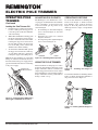
IMPORTANT: Read and understand this manual before assembling or
operating this Pole Trimmer. Improper use of Pole Trimmer can cause
severe injury or death. Keep this manual for future reference.
MODEL: 110946-01A
AXCESS TRIMMER™
Electric Pole Trimmer
OWNER’S MANUAL
If you have a question or problem,
CALL TOLL FREE 1-800-858-8501
or visit www.desatech.com

2
110939
ELECTRIC POLE TRIMMER
®
For more information, visit www.desatech.com
SAFETY
WARNINGS
BEFORE OPERATING POLE
TRIMMER
READ ALL INSTRUCTIONS BEFORE
OPERATING POLE TRIMMER.
1. Stay Alert – Watch what you are doing.
Use common sense when operating
Pole Trimmer.
2. Avoid Dangerous Environments
• Do not operate Pole Trimmer in rain
or in damp or wet locations.
• Do not operate Pole Trimmer while
under the influence of alcohol, medi-
cations, or drugs.
• Do not operate Pole Trimmer when
you are tired.
• Do not operate Pole Trimmer where
highly-flammable liquids or gases
are present.
• Do not operate Pole Trimmer while
standing on a ladder or in a tree.
• Do not operate Pole Trimmer if it is
damaged or not securely and fully
assembled.
3. Keep Children Away – Keep all visi-
tors a safe distance from work area.
4. Do not use Pole Trimmer for any job
except that for which it is intended.
5. Only well instructed adults should
operate Pole Trimmer. Never allow
children to operate Pole Trimmer.
6. Dress Properly When Operating
Pole Trimmer
• Do not wear loose clothing or jewelry
that can get caught in the moving
blades or parts of the Pole Trimmer.
WARNING: When using electric
Pole Trimmers, basic safety precau-
tions should always be followed
to reduce the risk of fire, electric
shock, and personal injury.
WARNING: This product
contains chemicals known to
the State of California to cause
cancer or birth defects, or other
reproductive harm.
• Always wear rubber gloves and
substantial foot wear when working
outside.
• Always wear protective hair covering
to contain long hair.
• Always wear a face or dust mask if
operation is dusty.
7. Always wear eye protection that meets
or exceeds the requirements of ANSI
Z87.1.
8. Use only electrical voltage noted on
model nameplate on Pole Trimmer.
WARNING: To reduce the risk
of electric shock, use only with an
extension cord intended for out-
door use, such as SW-A, SOW-A,
STW-A, STOW-A, SJW-A, SJOW-A,
SJTW-A, or SJTOW-A.
WHILE OPERATING POLE
TRIMMER
1. Stay Alert – Watch what you are doing.
Use common sense.
2. Be aware of extension cord while operat
-
ing Pole Trimmer. Be careful not to trip
over extension cord. Keep extension cord
away from cutter blades at all times.
3. Avoid Unintentional Starting – Do not
carry plugged-in Pole Trimmer with
finger on switch. Be sure switch is OFF
when plugging in Pole Trimmer.
4. Do Not Overreach – Keep proper
footing and balance at all times when
operating Pole Trimmer.
DANGER - RISK OF CUT
– Keep hands away from blades
at all times. Keep both hands on
handle areas when Pole Trimmer
is on. Do not attempt to remove cut
material nor hold material to be cut
when blades are moving. Do not
grasp the exposed cutting blades
or cutting edges when picking up
or holding the Pole Trimmer.
CAUTION - Blades coast after
turn off.
5. Disconnect Pole Trimmer – Discon-
nect the Pole Trimmer from the power
supply
• when not in use
• before servicing
• when changing accessories such as
blades
• when clearing jammed material from
blades
• when moving from one worksite to
another
6. Do Not Force Pole Trimmer – It will do
the job better and with less likelihood
of a risk of injury at the rate for which
it was designed.
7. Do Not Abuse Power Cord – Never
carry Pole Trimmer by power cord or
yank it to disconnect from receptacle.
Keep power cord from heat, oil, and
sharp edges.
8. Before starting Pole Trimmer, make
sure blades are not touching anything.
Total Length of Cord
Volts in Feet
120 25 50 100 150
Ampere
Rating AWG
0-6 18 16 16 14
10.
Provide Ground Fault Circuit Interrupter
(GFCI) protection on the circuit or outlet
to be used for Pole Trimmer. You may
use receptacles with built-in GFCI pro
-
tection for this safety measure.
11. Do not operate Pole Trimmer near
electric power lines, telephone, or cable
lines. Keep Pole Trimmer at least 10 feet
away from any power lines or cables.
9. Extension Cord – Make sure your
extension cord is in good condition.
When using an extension cord, be sure
to use one heavy enough to carry the
current your Pole Trimmer will draw.
An undersized extension cord will
cause a drop in line voltage resulting
in loss of power and overheating.
The table below shows the correct size
extension cord to use depending on cord
length and nameplate ampere rating. If
in doubt, use the next larger gage cord.
The smaller the gage number, the larger
the cord. To reduce the risk of discon-
nection of Pole Trimmer from the exten-
sion cord during operation, use the cord
hitch described in this manual.

3
110939
OWNER’S MANUAL
For more information, visit www.desatech.com
MAINTENANCE AND
STORAGE OF POLE
TRIMMER
1. Maintain Pole Trimmer With Care
• Keep cutting edge sharp and clean
for best performance and to reduce
the risk of injury
• Periodically apply a light coat of oil
to the cutter blades for lubrication
(motor oil is preferred).
•
Inspect Pole Trimmer cord periodi-
cally, and if damaged, have it repaired
by an authorized service facility
• Inspect extension cords periodically
and replace if damaged
• Keep handles dry, clean, and free
from oil and grease
2. Check Damaged Parts
• If a part is damaged, carefully check
the damaged part before using the
Pole Trimmer. Make sure the part
will operate properly and perform
its intended function.
• Check for alignment of moving parts,
binding of moving parts, breakage of
parts, mounting, and any other condi
-
tion that may affect its operation.
• A guard or other part that is damaged
should be properly repaired or replaced
by an authorized service center unless
indicated elsewhere in this manual.
3. When servicing Pole Trimmer, use only
identical replacement parts.
4. To reduce the risk of electric shock, the
Pole Trimmer has a polarized plug (one
blade is wider than the other) and will
require the use of a polarized extension
cord. The Pole Trimmer’s plug will fit
into a polarized extension cord only one
way. If the plug does not fit fully into
the extension cord, reverse the plug.
If the plug still does not fit, obtain a
correct polarized extension cord. A
polarized extension cord will require
the use of a polarized wall outlet. This
plug will fit into the polarized wall
outlet only one way. If the plug does
not fit fully into the wall outlet, reverse
the plug. If the plug still does not fit,
contact a qualified electrician to install
SAFETY
WARNINGS
Continued
PRODUCT IDENTIFICATION
the proper wall outlet. Do not change
the Pole Trimmer plug, extension cord
receptacle, or extension cord plug in
any way.
5. Store Idle Pole Trimmer Indoors
– When not in use, the Pole Trimmer
should be stored indoors in a dry loca-
tion. Store Pole Trimmer above the
reach of children or in a locked area
out of the reach of children.
This manual is your guide to safe and proper
operation of the Pole Trimmer.
SAVE THESE INSTRUCTIONS.
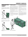
UNPACKING
1. Remove Pole Trimmer and all other items
from box. The Pole Trimmer comes fully
assembled and ready to use.
2. Check all items for shipping damage.
If you find any damage or if any parts
are missing, promptly inform the dealer
where you bought the Pole Trimmer or
call 1-800-858-8501.
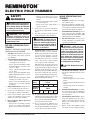
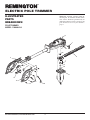
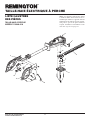
Figure 1 - Product Identification: Remington Pole Trimmer
Pivoting
Power Head
Cutter Blade
T-Handle
Bracket
Hand Guard
Forward Grip
Trigger Lever
Power Cord
Extension
Cord Retainer
Trigger
Housing
Trigger Lock Button
Cam-Levered Collet

4
110939
ELECTRIC POLE TRIMMER
®
For more information, visit www.desatech.com
OPERATING POLE
TRIMMER
WARNING: Read and under-
stand this owner’s manual before
operating Pole Trimmer. Make cer-
tain you read and understand all
Safety Warnings on pages 2 and
3 of this manual. Improper use
of this Pole Trimmer can result in
severe injury or death from fire,
electric shock, or body contact
with moving parts.
2. Grasp the power head motor housing
and rotate the power head to either the
0, 45, or 90 degree position.
CONNECTING EXTENSION
CORD
The Pole Trimmer has a built-in extension
cord retainer to prevent the accidental discon-
nection of the unit from the extension cord
during use. It is molded into the lower hand
guard area of the trigger housing.
1. Make sure the trigger lever is in the
OFF position (see Starting the Pole
Trimmer, page 5).
2. Plug the power cord into the extension
cord.
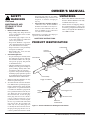
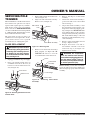
PIVOTING THE POWER HEAD
The Pole Trimmer is equipped with a power
head that pivots. The power head is able to
pivot a full 180 degrees. The power head
has a spring-loaded T-handle that allows it
to be locked into several different positions
within its 180-degree rotation.
Before connecting the Pole Trimmer to the
electrical supply, make sure the power head
is locked into position. Do this by trying to
rotate the power head in either direction. The
power head should be locked in position and
should not rotate.
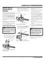
To pivot the power head, follow the instruc-
tions below.
1. Pull out on the T-handle located on the
side of the pivot bracket. The T-handle
is spring-loaded, so you will feel some
resistance when pulling it out.
3. Release the T-handle. It should snap
back into its seated position. If it does
not, rotate the power head back and
forth slightly until the T-handle snaps
back into its seated position. The power
head is now locked into position and
ready for use.
Figure 5 - Plugging Pole Trimmer Power
Cord to Extension Cord
Figure 3 - Rotating Power Head
Figure 4 - Locking Power Head Into
Position
Figure 2 - Pulling Out T-Handle to Rotate
Power Head
Cord Length AWG Cord Size
25 feet 18 AWG
50 feet 16 AWG
100 feet 16 AWG
150 feet 14 AWG
EXTENSION CORDS
Use proper extension cord with this Pole
Trimmer. Use only extension cords marked
for outdoor use. The cord must be marked
with suffix W or W-A following the cord type
designation.
Example: SJTW-A or SJTW.
Use proper sized cord with this Pole Trimmer.
Cord must be heavy enough to carry current
needed. An undersized cord will cause volt-
age drop at Pole Trimmer. Pole Trimmer will
lose power and overheat. Follow cord size
requirements listed below.
Keep cord away from cutting area. Make
sure cord does not catch on branches dur-
ing cutting. Inspect cord often. Replace
damaged cords.

5
110939
OWNER’S MANUAL
For more information, visit www.desatech.com
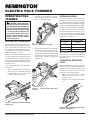
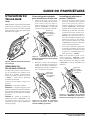
STARTING THE POLE
TRIMMER
The Pole Trimmer has a trigger lock button
located on top of the handle. This safety
feature locks the trigger in the OFF posi-
tion, preventing accidental starting of the
Pole Trimmer.
The trigger lock button has three posi-
tions.
Position 1 locks the trigger.
Position 2 allows you to squeeze the trigger
and operate the Pole Trimmer. The trigger
lock button will automatically spring back to
Position 1 when you release the trigger.
Position 3 allows you to lock the trigger
in the ON position. This is helpful during
continuous trimming for extended periods
of time.
Note: An optional method of retaining the
extension cord is shown in Figure 8 for use
with larger-gage cords that may not fit into
the extension cord retainer.
2.
Release the trigger lock button while the
Pole Trimmer is running. The lock button
resets to Position 1 each time you release
the trigger to the OFF position.
Figure 9 - Manually Operating Trigger with
Trigger Lock Button in Position 2
Figure 10 - Trigger in OFF Position with
Trigger Lock Button in Position 1
Trigger Lock
Button Position 2
Trigger Lock
Button Position 1
Figure 7 - Extension Cord Loop Tight
Around Molded Cord Hook
Figure 8 - Optional Method of Retaining
Extension Cord
Figure 6 - Inserting Extension Cord Loop
Through Bottom of Handle
Continued
Unlocking the Trigger to Start
the Pole Trimmer
1. Using your thumb, push the trigger lock
button forward to Position 2. Squeeze
the trigger lever to the ON position. The
Pole Trimmer will start running.
3. Create a loop in the extension cord and
insert the loop through the bottom of
the handle. Pull the loop tight around
the molded cord hook (see Figures 6
and 7).
OPERATING POLE
TRIMMER
Continued

6
110939
ELECTRIC POLE TRIMMER
®
For more information, visit www.desatech.com
OPERATING POLE
TRIMMER
Continued
Figure 13 - Trimming Tall Hedges or
Shrubs
Figure 14 - Trimming Smaller Hedges or
Shrubs
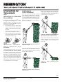
Locking the Pole Trimmer ON
1. Push the trigger lock button forward to
Position 2 and squeeze the trigger lever
to the ON position. The Pole Trimmer
will start running.
2.
While the Pole Trimmer is running, push
the trigger lock button forward again to
Position 3. Hold the button there while
releasing the trigger lever, then release
the lock button. This locks the trigger
lever in the ON position and the Pole
Trimmer will continue running.
3. To turn the Pole Trimmer OFF, squeeze
the trigger lever and release it. The trig-
ger lock button will reset to Position 1,
locking the trigger in the OFF position.
Note: If the Pole Trimmer is locked ON
during use and the Pole Trimmer becomes
disconnected from the power supply, Disen-
gage the lock ON feature before reconnecting
to the power supply.
USING THE POLE TRIMMER
The Pole Trimmer is a dual-purpose tool. It is
designed to trim and shape tall, hard-to-reach
hedges and bushes with its extended reach
and pivoting power head. You can also adjust
the Pole Trimmer to trim and shape smaller
hedges and shrubs near the ground without
having to bend or stoop.
Figure 11 - Locking Trigger in ON Position
with Trigger Lock Button in Position 3
Trigger Lock
Button Position 3
OPERATING POSITIONS
To use the Pole Trimmer for trimming tall,
hard-to-reach hedges or shrubs, hold the
Pole Trimmer at the positions shown in
Figure 13. Pivot the power head to several
different positions to shape or sculpt shrubs
or hedges.
To use the Pole Trimmer for trimming smaller
hedges or shrubs, hold the Pole Trimmer at
the positions shown in Figure 14.
ADJUSTING POLE LENGTH
The Remington
®
Pole Trimmer has a tele-
scoping pole assembly that has an extendable
range of 10 inches. A cam levered collet
is used to hold the pole in position at any
extended length.
1. To extend the pole, unlock the clamping
lever as shown in Figure 12. Pole will
slide freely.
2. Pull inner pole section out to desired
length of extension.
3. To lock pole in position, tighten clamping
lever as shown in Figure 12.
Figure 12 - Extending Telescopic Pole
UNLOCK
LOCK

7
110939
OWNER’S MANUAL
For more information, visit www.desatech.com
To use the Pole Trimmer for trimming
low-lying foliage or ground cover, hold
the Pole Trimmer at the position shown in
Figure 16.
Figure 16 - Trimming Low Foliage or
Ground Cover
Figure 15 - Trimming Bottoms and Sides
of Hedges and Shrubs
To use the Pole Trimmer for trimming the
bottoms and sides of hedges and shrubs, hold
the Pole Trimmer at the positions shown in
Figure 15.
OPERATING POLE
TRIMMER
Continued
TRIMMING A HEDGE
Use the Pole Trimmer properly. Always
wear eye protection, rubber gloves, and
substantial foot wear while using the Pole
Trimmer. Always maintain proper footing
and balance and never overreach when us
-
ing Pole Trimmer. Before starting the Pole
Trimmer, hold the unit with both hands on
the grip areas. Make sure that the cutter blade
is not touching anything.
Always keep the extension cord behind the
Pole Trimmer when in use. Do not drape
the cord over the hedge where it may be
cut by the blades.
Use smooth steady sweeping motions to trim
new growth. Do not try to cut too much at
one time. This can cause the Pole Trimmer
to slow down or get jammed, reducing the
cutting efficiency.
Figure 17 - Trimming Hedge
Do not force the Pole Trimmer through dense
growth. A slight back and forth sawing action
may ease the cutting of larger, more dense
growth. If the Pole Trimmer begins to slow
down, reduce the rate of speed at which you
are trying to cut.
If the Pole Trimmer becomes jammed, im-
mediately turn Pole Trimmer off. Discon
-
nect Pole Trimmer from the power supply
and remove the jammed debris from the
cutter blades.
Do not try to cut branches larger than
3/4 inch in diameter.
For best results, trim the sides of hedges with
an upward sweeping motion. Trim the hedges
so that the top is slightly narrower than the
bottom. To trim extremely level hedges, use a
string stretched along the length of the hedge
as a guide (see Figure 17).

8
110939
ELECTRIC POLE TRIMMER
®
For more information, visit www.desatech.com
CLEANING AND
MAINTENANCE
WARNING: Disconnect Pole
Trimmer from power supply before
cleaning or servicing. Severe in-
jury or death could occur from fire,
electrical shock, or body contact
with moving cutter blades.
WARNING: When cleaning
Pole Trimmer:
• Do not submerse Pole Trimmer
in any liquids
• Do not use products that con-
tain Ammonia, Chlorine, or
abrasives
• Do not use chlorinated cleaning
solvents, Carbon Tetrachloride,
Kerosene, or Gasoline.
Use a soft cloth dampened with a mild soap
and water mixture to wipe Pole Trimmer
pole, housing, and cutter blades clean. Do
not spray or pour water directly onto Pole
Trimmer.
Once the Pole Trimmer is cleaned, apply
a light coat of oil to the cutter blades to
prevent rust and provide lubrication (motor
oil is preferred).
TROUBLESHOOTING
Note: For additional help, visit our
technical service web site at www.de-
satech.com.
WARNING: Unplug Pole Trimmer from power source before servicing.
Severe injury or death could occur from fire, electrical shock, or body
contact with moving blades.
OBSERVED FAULT POSSIBLE CAUSE REMEDY
Motor does not run when you squeeze trig-
ger lever
1. Trigger lock button not pressed to release
trigger lever
2. Extension cord connection is loose
3. Household circuit breaker is tripped or
open line fuse
4. Bad motor brushes
5. Open wiring on Pole Trimmer
1. Push lock button forward and squeeze
trigger lever (see Starting the Pole Trim-
mer, page 5)
2. Check cord connections
3. Check circuit breaker or line fuse
4. Call for Technical Service
5. Call for Technical Service
Motor runs, but cutting blades do not move Pole Trimmer damaged. Do not use Pole
Trimmer
Call for Technical Service
Pole Trimmer smokes during operation Pole Trimmer damaged. Do not use Pole
Trimmer
Call for Technical Service

9
110939
OWNER’S MANUAL
For more information, visit www.desatech.com
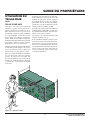
SERVICING POLE
TRIMMER
The Pole Trimmer is a double-insulated tool
and contains some parts that can only be
replaced with original parts by an Autho
-
rized Service Center. Visit our Technical
Service web site at www.desatech.com
or contact our Technical Service Department
at 1-800-858-8501 (English Only) for the
nearest Authorized Service Center.
The parts listed on pages 12 and 13 are
considered to be user replaceable. See Re-
placement Parts and Accessories, page 10,
for information on ordering these parts.
1. Unplug pole trimmer from power supply.
2. Place pole trimmer upside down on
workbench and remove the four (4)
bottom cover screws. Lift bottom cover
off (see Figure 18).
WARNING: To prevent serious
personal injury, wear gloves when
removing and installing the cut
-
ter blades. Do not place fingers
or hands between blades where
they could get cut.
BLADE REPLACEMENT
3. Remove M5 locknut and washer from
cam (see Figure 19).
4. Align cam and cutter blade assemby.
Remove cam. (see Figure 19).
Cover Screw
Bottom Cover
Figure 18 - Removing Bottom Cover from
Trimmer Head
M5 Locknut
Washer
Cam
Figure 19 - Removing Cam
Cutter Blade Assembly
Note: If binding occurs after reassembly,
repeat all of the previous steps making sure
that cam aligns properly with cutter blade
assembly.
WARNING: All components
must be installed and securely
fastened before plugging pole trim
-
mer into power supply. Failure to
do so may cause product damage
or serious personal injury.
5. Remove screw that holds down cutter
blade assembly (see Figure 20). IM-
PORTANT: Be sure not to loose the
8-32 locknut that secures this screw.
6. Remove and dispose of cutter blade
assembly.
7. Attach new cutter blade assembly to
power head with screw and locknut
removed in step 5.
8. Align cutter blade assembly so that
the cam will fit properly into the oval-
shaped lobes of the cutter blade assem
-
bly (see Figure 19). IMPORTANT: The
large diameter flange of the cam must
face upward away from the power head.
The small diameter flange of the cam
must line up with and sit directly on top
of the cam flange.
9. Replace washer and locknut removed
in step 3. Tighten securely.
10. Replace the bottom cover and se-
cure with the 4 bottom cover screws
removed in step 2 (see Figure 18).
Tighten screws securely.
Figure 20 - Removing Cutter Blade
Assembly
Screw
Cutter Blade
Assembly
Cam Flange
8-32 Locknut

10
110939
ELECTRIC POLE TRIMMER
®
For more information, visit www.desatech.com
REPAIR SERVICE
Note: Only use original replacement parts.
This will protect your warranty coverage for
parts replaced under warranty.
Each Authorized Service Center is indepen-
dently owned and operated.
For additional Service Center or warranty
information, call 1-800-858-8501 or visit
our Technical Service web site at www.
desatech.com.
WARRANTY SERVICE
If product requires warranty service, return
it to nearest Authorized Service Center.
You must show proof of purchase. If faulty
materials or workmanship caused damage,
we will repair or replace product without
charge. Note: Normal wear, misuse, abuse,
neglect, or accidental damage is not covered
under warranty.
NON-WARRANTY SERVICE
If product requires service, return it to nearest
Authorized Service Center. Repairs will be
billed to you at regular repair list prices.
TECHNICAL
SERVICE
You may have further questions about as-
sembling, operating, or maintaining this
product. If so, you can visit our Technical
Service web site at www.desatech.com
or contact our Technical Service Department
at 1-800-858-8501 (English Only). You may
also write to:
DESA Specialty Products™
ATTN: Technical Service Specialty Products
P.O. Box 90004
Bowling Green, KY 42102-9004
When contacting DESA Specialty Products™,
have ready
• Your Name
• Your Address
• Your Phone Number
• Model Number of Product
• Date of Purchase (Include copy of receipt
for written requests).
REPLACEMENT
PARTS AND
ACCESSORIES
For original replacement parts and acces-
sories, contact your nearest Authorized
Dealer or Authorized Service Center for this
product. If they can not supply the part or
accessory, contact your nearest Parts Central
listed on page 11. Each Authorized Dealer,
Authorized Service Center, and Parts Central
is independently owned and operated.
See pages 12 and 13 for an Illustrated Parts List.
If you need additional referral information,
contact our Technical Service Department
(see Technical Service).
In Canada call 1-800-561-3372 for parts
information.

11
110939
OWNER’S MANUAL
For more information, visit www.desatech.com
PARTS CENTRAL
Master Part Distributors
1251 Mound Avenue NW
Grand Rapids, MI 49504-2672
616-791-0505
1-800-446-1446
www.masterparts.net
Hance Distributors, Inc.
12795 16th Avenue North
Plymouth, MN 55441-4556
763-559-2299
www.hanceco.com
Automotive Equipment
Service
1651 E. Kansas City Road
Olathe, MO 66061
816-531-9144
1-800-843-3546
www.aes-lawnparts.com
Bowden Electric Motor
Service
1681 S. Wesleyan Blvd.
Rocky Mount, NC 27803
252-446-4203
East Coast Energy
10 East Route 36
West Long Branch, NJ 07764-1501
1-800-755-8809
Forrest Lytle and Sons, Inc.
740 West Galbraith Road
Cincinnati, OH 45231-6002
513-521-1464
Bortz Chain Saw Shop
Road #2, Box 64A
Oley, PA 19547-9412
610-987-6452
21st Century
2950 Fretz Valley Road
Perkasie, PA
18944-4034
215-795-0400
1-800-325-4828
La Porte’s
2444 N 5th Street
Hartsville, SC 29550-7704
843-332-0191
MTA Distributors
555 Hickory Hills Blvd.
Nashville, TN 37189-9244
615-299-8777
1-800-264-0225
Webbs Appliance Center
1519 Church Street
Nashville, TN 37203-3004
615-329-4079
1-800-899-4079
Industrial Hardware
4109 Bainbridge Blvd.
Chesapeake, VA 23324-1403
757-543-2232
1-800-788-0008
Mills Lawn and Garden
4750-B Baxter Road
Virginia Beach, VA 23462
757-490-7001
www.mills-parts.com
Tuco Industrial Products
5223 180th Street SW
Suite 4A-1
Lynnwood, WA 98037-4506
425-743-9533
1-800-735-1268
www.tucoheat.com
Ray’s Portable Heater Service
3191 Myers Road
Camino, CA 95709-9550
530-644-7716
Tool & Equipment Service
Solutions, LLC
5 Manila Drive
Hamden, CT 06514-0322
203-248-7553
1-800-397-7553
Grainger Parts Operation
1657 Shermer Road
Northbrook, IL 60062-5362
708-498-5900
1-800-323-0620
www.grainger.com
Portable Heater Parts
342 North County Road 400 East
Valparaiso, IN 46383-9704
219-462-7441
1-800-362-6951
www.portableheaterparts.com
sales@portableheaterparts.com
techservice@portableheaterparts.com
FBD
1349 Adams Street
Bowling Green, KY 42103-3414
270-846-1199
1-800-654-8534
Lyons & Lyons Sales Co. Inc.
Glen Arm Road
Glen Arm,
MD 21057-9454
301-665-6500
1-800-333-5966
lyonsco@erols.com

12
110939
ELECTRIC POLE TRIMMER
®
For more information, visit www.desatech.com
ILLUSTRATED
PARTS
BREAKDOWN
POLE TRIMMER
MODEL 110946-01A
6
7
5
21
19
20
18
4
3
2
17
1
9
15
10
14
13
12
11
8
16
Note: This assembly contains double-in-
sulated parts. To maintain double insula
-
tion, service should be performed by an
Authorized Service Center, except for the
parts shown. See Servicing Pole Trimmer,
page 9.

13
110939
OWNER’S MANUAL
For more information, visit www.desatech.com
PARTS LIST
POLE TRIMMER
MODEL 110946-01A
This list contains user replaceable parts used
in your Pole Trimmer. When ordering parts,
be sure to provide the correct model number
(from the model plate), then the part number
and description of the desired part.
KEY
NO.
PART
NO. DESCRIPTION
QTY.
1 110929-01 8-32 x 2" PH, PR Screw 1
2 116228-02 Bottom Cover 1
3 114958-02 Cutter Blade Assembly 1
4 115444-02 Cam 1
5 110925-01 .25" Push Nut 1
6 110933-01 Adjustment Knob Spring 1
7 110924-02 Lock Rod/Knob Assy. 1
8 107708-01 Screw, PPH, B, 8-18 x .88" 8
9 110906-02 Left Trigger Housing 1
10 110908-02 Lock ON/OFF lever 1
11 107694-01 Lock-out Spring 1
12 109357-01 Trigger Spring 1
13 107729-01 Micro Switch 1
14 110907-02 Trigger Lever 1
15 110905-02 Right Trigger Housing 1
16 111249-02 Shrouded Power Cord 1
17 116293-01 8-32 x 2" Truss Screw 4
18 118132-01 Cam Flange 1
19 118152-01 M5 Washer 1
20 118151-01 M5 Locknut 1
21 118258-01 8-32 Locknut 1

ELECTRIC POLE TRIMMER LIMITED WARRANTY
Always specify model and serial numbers when writing the factory.
We reserve the right to amend these specifications at any time without notice. The only warranty applicable is our standard written warranty. We
make no other warranty, expressed or implied.
DESA Specialty Products™ warrants this Electric Pole Trimmer and any parts thereof, to be free from defects in material and workmanship for
two years (90 days for reconditioned unit) from the date of first purchase from an authorized dealer, provided that the product has been properly
maintained and operated in accordance with all applicable instructions. The bill of sale or proof of purchase must be presented at the time a claim
is made under this warranty.
This warranty is extended only to the original retail purchaser. This warranty covers only the parts and labor required to restore this Pole Trimmer
to its proper operating condition. Warranty parts must be obtained through factory authorized dealers and service centers for this product. These
dealers and service centers will provide original factory replacement parts. Failure to use original factory replacement parts voids this warranty.
This warranty does not cover commercial, industrial, or rental usage, nor does it apply to parts that are not in original condition because of normal
wear and tear, or parts that fail or become damaged as a result of misuse, accident, lack of proper maintenance, tampering, or alteration. Travel,
handling, transportation, and incidental costs associated with warranty repairs are not reimbursable under this warranty and are the responsibility
of the owner.
To the full extent allowed by the law of the jurisdiction that governs the sale of the product, this express warranty excludes any and all other
expressed warranties and limits the duration of any and all implied warranties, including warranties of merchantability and fitness for a particular
purpose to two years form the date of first purchase, and DESA Specialty Products’™ liability is hereby limited to the purchase price of the product
and DESA Specialty Products™ shall not be liable for any other damages whatsoever including indirect, incidental, or consequential damages.
Some states do not allow limitation of how long an implied warranty lasts or an exclusion or limitation of incidental or consequential damages,
so the above limitation of damages may not apply to you.
This warranty provides the original purchaser with specific rights. For information regarding those rights, please consult the applicable state laws.
P.O. Box 90004
Bowling Green, KY 42102-9004
www.desatech.com
Industries of Canada, Inc.
2220 Argentia Road
Unit #4
Mississauga, Ontario
L5N 2K7
905-826-8010
FAX 905-826-8236
Model ______________
Date Purchased ______________

IMPORTANTE: Lea y entienda este manual antes de ensamblar
u operar esta podadora de pértiga. El uso inadecuado de esta
podadora puede ocasionar graves lesiones o la muerte. Guarde
este manual para futura referencia.
MODELO:
110946
-01A
Si tiene preguntas o problemas,
LLAME GRATIS al 1-800-858-8501
(sólo en inglés) o visite el sitio www.
desatech.com
®
AXCESS TRIMMER™
Podadora Eléctrica De Pértiga
MANUAL DEL PROPIETARIO

16
110939
PODADORA ELÉCTRICA DE PÉRTIGA
Para más información, visite www.desatech.com
®
ADVERTENCIAS
DE SEGURIDAD
ANTES DE OPERAR LA
PODADORA DE PÉRTIGA
LEA TODAS LAS INSTRUCCIONES
ANTES DE OPERAR LA PODADORA
DE PÉRTIGA.
1. Esté alerta - Mire lo que hace. Use
el sentido común cuando opere la po
-
dadora de pértiga.
2. Evite ambientes peligrosos -
• No opere la podadora de pértiga en
la lluvia o en lugares húmedos o
mojados.
• No opere la podadora de pértiga si
está bajo la influencia del alcohol,
medicinas o drogas.
• No opere la podadora de pértiga si
está cansado.
• No opere la podadora de pértiga
cuando haya presencia de líquidos o
gases altamente inflamables.
• No opere la podadora de pértiga si
está sobre una escalera o un árbol.
• No opere la podadora de pértiga si
está dañada o si no está bien y com-
pletamente ensamblada.
3. Mantenga a los niños lejos -
Mantenga a todos los visitantes a una
distancia segura del área de trabajo.
4. Use la podadora sólo en el trabajo para
el que fue concebida.
5. La podadora de pértiga debería ser
operada sólo por personas adultas bien
preparadas. Nunca permita que los
niños la operen.
ADVERTENCIA: Cuando use
podadoras eléctricas de pértiga,
deben acatarse siempre las pre
-
cauciones básicas de seguridad
para reducir el riesgo de incen-
dio, sacudida eléctrica, y lesión
personal.
ADVERTENCIA: Este produc-
to contiene químicos que según
el estado de California causa
cáncer, defectos congénitos, u
otros daños reproductivos.
6. Vístase correctamente cuando
opere la podadora de pértiga.
• No use ropa floja ni joyería que pueda
agarrarse en las cuchillas móviles o en
las piezas de la podadora de pértiga.
• Use siempre guantes de goma y
calzado robusto cuando trabaje a la
intemperie.
• Use siempre un gorro protector de
cabello para cubrir cabellos largos.
• Use siempre una máscara facial o
para el polvo si opera en sitios pol-
vorientos.
7. Use siempre un protector visual igual o
mejor que lo que exige la norma ANSI
Z87.1.
8. Use sólo el voltaje eléctrico indicado
en la placa del modelo de la podadora
de pértiga.
ADVERTENCIA: Para reducir
el riesgo de choque eléctrico, úse
-
la sólo con un cordón de extensión
destinado para uso a la intemperie,
tales como SW-A, SOW-A, STW-A,
STOW-A, SJW-A, SJOW-A, SJTW-
A, ó SJTOW-A.
MIENTRAS OPERE LA
PODADORA DE PÉRTIGA
1. Esté alerta - Mire lo que está hacien-
do. Use el sentido común.
2. Esté consciente del cordón de extensión
mientras opere la podadora de pértiga.
Tenga cuidado de no tropezarse en el
cordón de extensión. Mantenga siem-
pre el cordón de extensión lejos de las
cuchillas cortantes.
3. Evite arranques imprevistos - No
lleve la podadora de pértiga enchufada
con el dedo en el gatillo. Asegúrese
que el interruptor esté en OFF cuando
enchufe la podadora.
4. No extienda mucho el cuerpo
- Mantenga siempre el equilibrio y la
estabilidad en los pies cuando opere la
podadora de pértiga.
PELIGRO - RIESGO DE
CORTE - Mantenga siempre las
manos lejos de las cuchillas.
Cuando la podadora de pértiga
esté encendida mantenga ambas
manos en las áreas del mango. No
trate de retirar material cortado
ni sostener el material que va a
cortar cuando las cuchillas están
moviéndose. No agarre de las
cuchillas cortantes expuestas ni
de los bordes cortantes cuando
levante o sostenga la podadora.
Longitud total del
Voltaje cordón en pies
120 25 50 100 150
Capacidad
en amperios AWG
0-6 18 16 16 14
10. Ponga protección GFCI (Cortacircuitos
de falla a tierra) en el circuito o toma
que va usarse con la podadora. Puede
usar tomacorriente con protección
GFCI incorporada como medida de
seguridad.
11. No opere la podadora de pértiga cerca
de líneas eléctricas de energía, líneas
telefónica o con cable. Mantenga la
podadora de pértiga al menos a 10 pies
lejos de las líneas o cables de energía.
9. Cordón de extensión - Asegúrese
que su cordón de extensión esté en
buenas condiciones. Cuando lo use,
asegúrese de usar uno lo suficiente-
mente grueso para que transporte la
corriente absorbida por su podadora
de pértiga. Un cordón de extensión
subdimensionado producirá caída de
voltaje en la línea ocasionando pérdida
de potencia y sobrecalentamiento.
La tabla a continuación le indica el ta
-
maño correcto del cordón de extensión
que debe usarse, dependiendo de la
longitud del cordón y de los amperios
nominales indicados en la placa de
características. Si tiene duda, use el
cordón de calibre inmediato superior.
A menor número de calibre, más grueso
es el cordón. Para reducir, mientras
funciona, el riesgo que la podadora de
pértiga se desconecte del cordón de
extensión, use el gancho del cordón
descrito en este manual.

17
110939
MANUAL DEL PROPIETARIO
Para más información, visite www.desatech.com
MANTENIMIENTO Y
ALMACENAJE DE LA
PODADORA DE PÉRTIGA
1. Mantenga la podadora de pértiga
con esmero
• Para un desempeño óptimo y para
reducir el riesgo de lesión mantenga
el borde cortante afilado y limpio.
• Aplique periódicamente una ligera
capa de aceite a las cuchillas cortan
-
tes para lubricarlas (es preferible el
aceite del motor).
• Inspeccione periódicamente el cor-
dón de la podadora y, si está dañado,
hágalo reparar en una instalación de
servicio autorizada.
• Inspeccione periódicamente los cor-
dones de extensión y reemplácelos si
están dañados.
• Mantenga los mangos secos, limpios
y sin aceite ni grasa.
2. Revise las piezas dañadas
• Si una pieza está dañada, revise cuida-
dosamente esta pieza dañada antes de
usar la podadora de pértiga. Asegúre
-
se que la pieza opere correctamente
y desempeñe su función específica.
• Revise la alineación de las piezas
móviles, pegado de piezas móviles,
rotura de piezas, montaje, y cualquier
otra condición que puede afectar su
operación.
• Una protección u otra pieza que esté
dañada debería repararse correcta-
mente en un centro de servicio au
-
torizado a no ser que en este manual
se indique otro lugar.
3. Cuando dé servicio a la podadora de
pértiga use sólo piezas de repuesto
idénticas.
ADVERTENCIAS
DE SEGURIDAD
DESEMPAQUE
1. Retire la podadora de pértiga y todos
los otros elementos de la caja. La po-
dadora de pértiga viene completamente
ensamblada y lista para usar.
2. Revise en todos los elementos algún
daño en el transporte. Si encuentra
algún daño o si faltan piezas, informe
enseguida al distribuidor donde compró
la podadora de pértiga o llame al 1-800-
858-8501 (sólo en inglés).
PRECAUCIÓN - Las cuchillas
continúan moviéndose después
de apagado.
5. Desconecte la podadora de pérti-
ga - Desconecte la podadora de pértiga
de la fuente de alimentación.
• Cuando no la use.
• Antes de darla servicio.
• Cuando cambie accesorios tales
como cuchillas.
• Cuando limpie material atascado en
las cuchillas.
• Cuando la mueva de un sitio de tra
-
bajo a otro.
6. No fuerce la podadora de pértiga
- Hará el trabajo mejor y con menor
posibilidad de lesión a la velocidad para
la que fue concebida.
7. No maltrate el cordón de alimen-
tación - Nunca lleve la podadora de
pértiga sosteniéndola del cordón ni
hale el cordón para desconectarla del
tomacorriente. Mantenga el cordón de
alimentación lejos del calor, aceite y de
bordes cortantes.
8. Antes de arrancar la podadora de pér
-
tiga, asegúrese que las hojas no topen
en nada.
4. Para reducir el riesgo de sacudida
eléctrica, la podadora de pértiga tiene
un enchufe polarizado (una cuchilla
es más ancha que la otra) y deberá
usarse un cordón de extensión pola-
rizado. El enchufe de la podadora de
pértiga se adapta a una extensión sólo
de una manera. Si el enchufe no se
adapta completamente en el cordón de
extensión, invierta el enchufe. Si aún
así no se adapta, consiga el cordón de
extensión correcto. Un cordón de ex
-
tensión polarizado requiere el uso de un
tomacorriente de pared polarizado. Este
enchufe se adapta a un tomacorriente
polarizado sólo de una manera. Si el
enchufe no se adapta completamente
en el tomacorriente de pared, invierta el
enchufe. Si el enchufe aún no se adapta
llame a un electricista calificado para
que instale el tomacorriente de pared
correcto. No haga ningún cambio de
enchufe de la podadora, ni de la toma
del cordón de extensión, ni del enchufe
del cordón de extensión.
5. Guarde bajo techo la podadora
de pértiga inactiva - Cuando no la
use, la podadora de pértiga se la debe
guardar en un lugar seco. Guarde la
podadora de pértiga por encima del
alcance de los niños o en un lugar bajo
llave fuera del alcance de los niños.
Este manual es su guía para una operación se
-
gura y correcta de la podadora de pértiga.
GUARDE ESTAS INSTRUCCIONES
Continuación

18
110939
PODADORA ELÉCTRICA DE PÉRTIGA
Para más información, visite www.desatech.com
®
OPERACIÓN DE LA
PODADORA
ADVERTENCIA: Antes de
operar la podadora de pértiga lea
y entienda este manual. Asegú-
rese de haber leído y entendido
todas las Advertencias de segu-
ridad de las páginas 16 y 17 de
este manual. El uso indebido de
esta podadora de pértiga puede
ocasionar graves lesiones o la
muerte por incendio, sacudida
eléctrica o contacto del cuerpo
con partes móviles.
GIRO DE LA CABEZA DE
POTENCIA
La podadora de pértiga viene equipada con
una cabeza de potencia que gira. La cabeza de
potencia puede girar 180 grados. La cabeza
de potencia tiene un mango en T con carga
de resorte lo que le permite bloquearse en
diferentes posiciones dentro de su rotación
de 180 grados.
Antes de conectar la podadora de pértiga
a la fuente de alimentación, asegúrese que
la cabeza de potencia esté bloqueada en su
posición. Haga esto tratando de girar la ca-
beza de potencia en cualquier dirección. La
cabeza de potencia debería estar bloqueada
en esa posición y no girar.
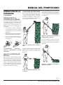
Para girar la cabeza de potencia siga las
instrucciones que vienen a continuación:
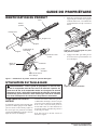
1. Hale hacia fuera el mango en T ubicado
lateralmente en el soporte giratorio. El
mango en T tiene resorte de carga, de
modo que sentirá alguna resistencia
cuando lo empuje hacia fuera.
Figura 2 - Hale hacia fuera el mango en T
para girar la cabeza de potencia
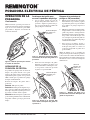
IDENTIFICACIÓN DEL PRODUCTO
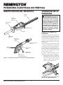
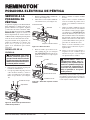
Figura 1 - Identificación del producto: Podadora de pértiga Remington
Cabeza
giratoria de
potencia
Cuchilla
cortante
Mango en T
Soporte
Protector de
la mano
Agarradera
frontal
palanca del
gatillo
Cordón de
alimentación
Retenedor del
cordón de extensión
Carcasa
del gatillo
Botón de
bloqueo del
gatillo
Collar de palanca
de leva

19
110939
MANUAL DEL PROPIETARIO
Para más información, visite www.desatech.com
2. Agarre la carcasa del motor de la cabeza
de potencia y gire la cabeza de potencia
a la posición de 0, 45 o 90 grados.
CONEXIÓN DEL CORDÓN DE
EXTENSIÓN
La podadora de pértiga tiene incorporado un
retén para el cordón de extensión para evitar
que la unidad se desconecte accidentalmente
del cordón de extensión durante el uso. Viene
moldeado en la protección inferior de la
mano de la carcasa del gatillo.
1. Asegúrese que la palanca del gatillo
esté en la posición OFF (Apagado)
(vea Arranque de la podadora de pér-
tiga, página 20).
2. Enchufe el cordón de alimentación en
el cordón de extensión.
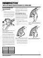
3. Suelte el mango en T. Debería regresar
y asentarse a presión en su posición. Si
no lo hace, gire de nuevo con suavidad
la cabeza de potencia hacia atrás y ade
-
lante hasta que el mango en T regrese y
se asiente a presión en su posición. La
cabeza de potencia está ahora bloquea
-
da en posición y lista para usarse.
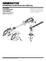
Figura 5 - enchufado del cordón de
alimentación de la podadora de pértiga
al cordón de extensión
Figura 3 - Cabeza giratoria de potencia
Figura 4 - Bloqueo de la cabeza de
potencia en posición
Longitud Calibre AWG
del cordón del cordón
25 pies 18 AWG
50 pies 16 AWG
100 pies 16 AWG
150 pies 14 AWG
CORDONES DE EXTENSIÓN
Use siempre los cordones de extensión apro-
piados para esta podadora. Use solamente
cordones de extensión marcados para uso
a la intemperie. El cordón debe estar mar-
cado con el sufijo W o W-A seguido de la
designación del tipo de cordón. Ejemplo:
SJTW-A ó SJTW.
Mantenga el cordón lejos del área cortante.
Asegúrese que el cordón no se agarre en las
ramas durante el corte. Inspeccione a menudo
el cordón. Reemplace los cordones dañados.
Figura 7 - El lazo del cordón de extensión
se aprieta alrededor del gancho moldeado
para el cordón
Figura 6 - Colocación del lazo del cordón
de extensión por la parte inferior del
mango
3. Haga un lazo en el cordón de extensión
e inserte el lazo por la parte inferior del
mango. Hale el lazo hasta que apriete
alrededor del gancho moldeado para el
cordón (vea las Figuras 6 y 7).
Use el tamaño de cordón apropiado para
esta podadora de pértiga. El cordón debe
ser lo suficientemente grueso para que
transporte la corriente necesaria. Un cordón
subdimensionado ocasionará caída de vol-
taje en la podadora de pértiga. La podadora
perderá potencia y se sobrecalentará. Siga
los requisitos listados más abajo referentes
al tamaño del cordón.
Continúa
OPERACIÓN DE LA
PODADORA
Continuación

20
110939
PODADORA ELÉCTRICA DE PÉRTIGA
Para más información, visite www.desatech.com
®
OPERACIÓN DE LA
PODADORA
Continuación
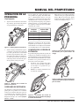
Bloqueo de la podadora de
pértiga en ON (encendido)
1. Empuje el botón de bloqueo del gatillo
hacia delante a la posición 2 y apriete
la palanca del gatillo a la posición ON.
La podadora de pértiga empezará a
funcionar.
2. Mientras la podadora está funcionando,
empuje de nuevo el botón de bloqueo del
gatillo a la posición 3. Sostenga el botón
ahí mientras suelta la palanca del gatillo,
luego suelte el botón de bloqueo. Con
esto se bloquea la palanca del gatillo en
la posición ON y la podadora de pértiga
continuará funcionando.
3. Para apagar la podadora, apriete y
suelte la palanca del gatillo. El botón
de bloqueo del gatillo se volverá a la
posición 1 bloqueando el gatillo en la
posición OFF.
Nota: Si durante el uso la podadora de
pértiga está bloqueada en ON y la podadora
se desconecta de la fuente de alimentación.
Desenganche la característica de bloqueo en
ON antes de volver a conectar la energía de
alimentación.
Figura 11 - Bloqueo del gatillo en la
posición ON con el botón de bloqueo del
gatillo en la posición 3
Botón de
bloqueo del
gatillo en la
posición 3
ARRANQUE DE LA
PODADORA DE PÈRTIGA
La podadora de pértiga tiene un botón de
bloqueo del gatillo ubicado en la parte
superior del mango. Esta característica de
seguridad bloquea el gatillo en la posición
OFF, evitando que la podadora de pértiga
arranque accidentalmente.
El botón de bloqueo del gatillo tiene 3
posiciones.
Posición 1 Bloquea el gatillo.
Posición 2 Permite que usted apriete el ga-
tillo y opere la podadora de pértiga. El botón
de bloqueo del gatillo regresará por resorte a
la posición 1 cuando suelte el gatillo.
Posición 3 Permite bloquear el gatillo en la
posición ON (prendido). Esto es útil durante
un podado continuo por largos períodos de
tiempo.
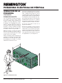
Nota: un método opcional para retener el
cordón de extensión se muestra en la Figura
8 que se usa con cordones de gran calibre
que pueden no adaptarse al retenedor del
cordón de extensión.
2. Suelte el botón de bloqueo del gatillo
mientras la podadora de pértiga está
funcionando. El botón de bloqueo vuel
-
ve a la posición 1 cada vez que suelta
el gatillo a la posición OFF.
Figura 9 - Operación manual del gatillo
con el botón de bloqueo del gatillo en la
posición 2
Figura 10 - Gatillo en la posición OFF
con el botón de bloqueo del gatillo en
la posición 1
Botón de bloqueo
del gatillo en la
posición 2
Botón de bloqueo
del gatillo en la
posición 1
Figura 8 - Método opcional para retener
el cordón de extensión
Desbloqueo del gatillo para
arrancar la podadora de pértiga
1. Con su pulgar, empuje el botón de
bloqueo del gatillo hacia delante a la
posición 2. Apriete la palanca del ga
-
tillo a la posición ON. La podadora de
pértiga empieza a funcionar.
La page est en cours de chargement...
La page est en cours de chargement...
La page est en cours de chargement...
La page est en cours de chargement...
La page est en cours de chargement...
La page est en cours de chargement...
La page est en cours de chargement...
La page est en cours de chargement...
La page est en cours de chargement...
La page est en cours de chargement...
La page est en cours de chargement...
La page est en cours de chargement...
La page est en cours de chargement...
La page est en cours de chargement...
La page est en cours de chargement...
La page est en cours de chargement...
La page est en cours de chargement...
La page est en cours de chargement...
La page est en cours de chargement...
La page est en cours de chargement...
La page est en cours de chargement...
La page est en cours de chargement...
La page est en cours de chargement...
La page est en cours de chargement...
-
 1
1
-
 2
2
-
 3
3
-
 4
4
-
 5
5
-
 6
6
-
 7
7
-
 8
8
-
 9
9
-
 10
10
-
 11
11
-
 12
12
-
 13
13
-
 14
14
-
 15
15
-
 16
16
-
 17
17
-
 18
18
-
 19
19
-
 20
20
-
 21
21
-
 22
22
-
 23
23
-
 24
24
-
 25
25
-
 26
26
-
 27
27
-
 28
28
-
 29
29
-
 30
30
-
 31
31
-
 32
32
-
 33
33
-
 34
34
-
 35
35
-
 36
36
-
 37
37
-
 38
38
-
 39
39
-
 40
40
-
 41
41
-
 42
42
-
 43
43
-
 44
44


Remington Power Tools 110946-01A Manuel utilisateur
- Catégorie
- Outils de jardin
- Taper
- Manuel utilisateur
dans d''autres langues
Documents connexes

Autres documents
-
Remington Axcess 117535-01A Manuel utilisateur
-
-
-
-
Desa 110946-01 Manuel utilisateur
-
-
-
-
Ryobi RPT400 Manuel utilisateur
-
Remington HT2516A Manuel utilisateur