X-POWER 9027251 Le manuel du propriétaire
- Taper
- Le manuel du propriétaire

9027251
1 In. Belt Sander
User Manual
227541

SPECIFICATIONS
Electrical Rating
120V~ / 60Hz / 2.1 A
Belt Speed
3,260 FPM
Belt Size
1″ x 30″
Dust Port
1-3/4″ OD
SAFETY
WARNING! Read and understand all instructions before using this tool. The
operator must follow basic precautions to reduce the risk of personal injury
and/or damage to the equipment.
Keep this manual for safety warnings, precautions, operating or inspection and
maintenance instructions.
HAZARD DEFINITIONS
Please familiarize yourself with the hazard notices found in this manual. A notice
is an alert that there is a possibility of property damage, injury or death if certain
instructions are not followed.
DANGER! This notice indicates an immediate and specific hazard that
will
result in
severe personal injury or death
if the proper precautions
are not taken.
WARNING! This notice indicates a specific hazard or unsafe practice that
could
result in
severe personal injury or death
if the proper
precautions are not taken.
CAUTION!
This notice indicates a potentially hazardous situation that may result in
minor or moderate injury if proper practices are not taken.
NOTICE!
This notice indicates that a specific hazard or unsafe practice will result
in equipment or property damage, but not personal injury.

GENERAL TOOL SAFETY WARNINGS
1.
Keep guards in place and in working order.
2.
Remove adjusting keys and wrenches. Form habit of checking to see that
keys and adjusting wrenches are removed from tool before turning it on.
3.
Keep work area clean. Cluttered areas and benches invite accidents.
4.
Don’t use in dangerous environment. Don’t use power tools in damp or wet
locations, or expose them to rain. Keep work area well lighted.
5.
Keep children away. All visitors should be kept safe distance from work
area.
6.
Make workshop kid proof with padlocks, master switches, or by removing
starter keys.
7.
Don’t force tool. It will do the job better and safer at the rate for which it
was designed.
8.
Use right tool. Don’t force tool or attachment to do a job for which it was
not designed.
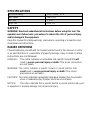
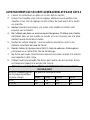
TABLE A: RECOMMENDED MINIMUM WIRE GAUGE FOR
EXTENSION CORDS (120 VOLT)
Nameplate Amperes
(at Full Load)
Extension Cord Length
25′
50′
100′
150′
0 – 6
18
16
16
14
6.1 – 10
18
16
14
12
10.1 – 12
16
16
14
12
12.1 – 16
14
12
Do Not Use.
9.
Use proper extension cord. Make sure your extension cord is in good
condition. When using an extension cord, be sure to use one heavy enough
to carry the current your product will draw. An undersized cord will cause a
drop in line voltage resulting in loss of power and overheating. Table A
shows the correct size to use depending on cord length and nameplate
ampere rating. If in doubt, use the next heavier gauge. The smaller the
gauge number, the heavier the cord.

10.
Wear proper apparel. Do not wear loose clothing, gloves, neckties, rings,
bracelets, or other jewelry which may get caught in moving parts. Nonslip
footwear is recommended. Wear protective hair covering to contain long
hair.
11.
Always use safety glasses. Also use face or dust mask if sanding operation
is dusty. Everyday eyeglasses only
have impact resistant lenses,
they are
not safety glasses.
12.
Don’t overreach. Keep proper footing and balance at all times.
13.
Maintain tools with care. Keep tools clean for best and safest performance.
Follow instructions for lubricating and changing accessories.
14.
Disconnect tools before servicing; when changing accessories, such as
belts.
15.
Reduce the risk of unintentional starting. Make sure switch is in off position
before plugging in.
16.
Use recommended accessories. Consult the owner’s manual for
recommended accessories. The use of improper accessories may cause
risk of injury to persons.
17.
Never stand on tool. Serious injury could occur if the tool is tipped or if the
belt is unintentionally contacted.
18.
Check damaged parts. Before further use of the tool, a guard or other part
that is damaged should be carefully checked to determine that it will operate
properly and perform its intended function – check for alignment of moving
parts, binding of moving parts, breakage of parts, mounting, and any other
conditions that may affect its operation. A guard or other part that is
damaged should be properly repaired or replaced.
19.
Direction of feed. Feed work into a belt against the direction of rotation of
the belt only.
20.
Never leave tool running unattended. Turn power off. Don’t leave tool until it
comes to a complete stop.
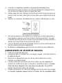
GROUNDING INSTRUCTIONS
DANGER! To prevent electric shock and death from incorrect grounding wire
connection read and follow these instructions:
10-120 V~ Grounded Tools: Tools with Three Prong Plugs

1.
In the event of a malfunction or breakdown, grounding provides a path of
least resistance for electric current to reduce the risk of electric shock. This
tool is equipped with an electric cord having an equipment-grounding
conductor and a grounding plug. The plug must be plugged into a matching
outlet that is properly installed and grounded in accordance with all local
codes and ordinances.
2.
Do not modify the plug provided – if it will not fit the outlet, have the proper
outlet installed by a qualified electrician.
3.
Improper connection of the equipment-grounding conductor can result in a
risk of electric shock. The conductor with insulation having an outer surface
that is green with or without yellow stripes is the equipment-grounding
conductor. If repair or replacement of the electric cord or plug is necessary,
do not connect the equipment grounding conductor to a live terminal.
4.
Check with a qualified electrician or service personnel if the grounding
instructions are not completely understood, or if in doubt as to whether the
tool is properly grounded.
5.
Use only 3-wire extension cords that have 3-prong grounding plugs and 3-
pole receptacles that accept the tool’s plug.
6.
Repair or replace damaged or worn cord immediately.
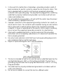
7.
This tool is intended for use on a circuit that has an outlet that looks like the
one illustrated above in 125 V~ 3-Prong Plug and Outlet. The tool has a
grounding plug that looks like the plug illustrated above in 125 V~ 3-Prong
Plug and Outlet.
8.
The outlet must be properly installed and grounded in accordance with all
codes and ordinances.
9.
Do not use an adapter to connect this tool to a different outlet.

SANDER SAFETY WARNINGS
1.
Wear eye protection.
2.
Support workpiece with miter gauge, backstop, or worktable.
3.
Maintain 1/16 inch maximum clearance between table and sanding belt or
disc.
4.
The backstop is a fence near the surface that helps the operator maintain
control of the workpiece and prevents the workpiece from being pulled into
the machine. For safety, it must be adjusted very close to the sanding
surface.
5.
The worktable is the surface mounted close to the sanding surface that the
operator rests the workpiece against to prevent it from being pulled by the
sanding surface. For safety, it must be adjusted very close to the sanding
surface.
6.
The sanding belt is designed to rotate down towards the table while the disc
rotates both up from the table and down towards the table.
7.
Do not operate with any guard disabled, damaged, or removed. Moving
guards must move freely and close instantly.
8.
The use of accessories or attachments not recommended by the
manufacturer may result in a risk of injury to persons.
9.
When servicing use only identical replacement parts.
10.
Do not depress the spindle lock when starting or during operation.
11.
Only use safety equipment that has been
approved by an appropriate
standards agency. Unapproved safety equipment may not provide adequate
protection. Eye protection must be ANSI-approved and breathing protection
must be NIOSH-approved for the specific hazards in the work area.
12.
Stay alert, watch what you are doing and use common sense when
operating a power tool. Do not use a power tool while you are tired or under
the influence of drugs, alcohol or medication. A moment of inattention while
operating power tools may result in serious personal injury.
13.
Industrial applications must follow OSHA guidelines.
14.
Maintain labels and nameplates on the tool. These carry important safety
information.

15.
Avoid unintentional starting. Prepare to begin work before turning on the
tool.
16.
People with pacemakers should consult their physician(s) before use.
Electromagnetic fields in close proximity to heart pacemaker could cause
pacemaker interference or pacemaker failure.
17.
The warnings, precautions, and instructions discussed in this instruction
manual cannot cover all possible conditions and situations that may occur.
It must be understood by the operator that common sense and caution are
factors, which cannot be built into this product, but must be supplied by the
operator.
VIBRATION SAFETY
This tool vibrates during use. Repeated or long-term exposure to vibration may
cause temporary or permanent physical injury, particularly to the hands, arms
and shoulders. To reduce the risk of vibration-related injury:
1.
Anyone using vibrating tools regularly or for an extended period should first
be examined by a doctor and then have regular medical check
-
ups to
ensure medical problems are not being caused or worsened from use.
Pregnant women or people who have impaired blood circulation to the
hand, past hand injuries, nervous system disorders, diabetes, or Raynaud’s
Disease should not use this tool. If you feel any medical or physical
symptoms related to vibration (such as tingling, numbness, and white or
blue fingers), seek medical advice as soon as possible.
2.
Do not smoke during use. Nicotine reduces the blood supply to the hands
and fingers, increasing the risk of vibration-related injury.
3.
Use tools with the lowest vibration when there is a choice between different
processes.
4.
Include vibration-free periods each day of work.
5.
Grip workpiece as lightly as possible (while still keeping safe control of it).
Let the tool do the work.
6.
To reduce vibration, maintain the tool as explained in this manual. If any
abnormal vibration occurs, stop use immediately.

UNPACKING
WARNING! Do not operate the tool if any part is missing. Replace the
missing part before operating. Failure to do so could result in a malfunction
and personal injury.
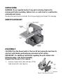
Remove the parts and accessories from the packaging and inspect for damage.
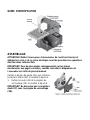
IDENTIFICATION KEY
ASSEMBLY
CAUTION! Turn the Power Switch of the tool off and unplug the tool from its
electrical outlet before performing any procedure in this section.
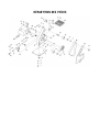
IMPORTANT! For additional information regarding the parts listed in the
following pages, refer to the Assembly
Diagram near the end of this manual.
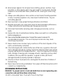
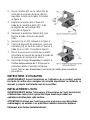
1.
Remove Guard Knob (44) and take off the
Side Guard (43). See Figure A.

2.
Remove the Bolt (45) from the
Locking Handle (29). See Figure B.
IMPORTANT! Do not lose the Toothed
Washer (27) under the Locking Handle
(29).
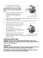
3.
Place the Table (40) on the Frame (14)
so that the Sanding Belt (42) fits
through the slot in the Table. See
Figure B.
4.
Replace the Bolt (45) and secure it using the Toothed Washer (27) and
Locking Handle (29). See Figure B.
5.
Replace the Side Guard (43) and secure it using the Guard Knob (44).
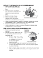
6.
Loosen the Screw (32) shown in Figure C.
7.
Place the Spark Guard (34) on the top of
the Frame and secure using the Screw
(32). See Figure C
8.
Place the Belt Sander on a secure
workbench able to carry the weight of the
Belt Sander and stock.
9.
Attach the vacuum hose (if used) to the 1-
3/4” dust port on the Side Guard. See
Figure A. Otherwise, attach a vacuum bag (not supplied) to the port to
collect the dust.
OPERATING INSTRUCTIONS
WARNING! Read the entire important safety information section at the
beginning of this manual including all text under subheadings therein before
set up or use of this product.
TOOL SET UP
WARNING! Turn the Power Switch of the tool off and unplug the tool from its
electrical outlet before performing any procedure in this section.
CAUTION! Do not operate with any guard disabled, damaged, or removed.
Moving guards must move freely and close instantly.

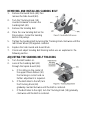
REMOVING AND INSTALLING SANDING BELT
1.
Remove the Guard Knob (44), then
remove the Side Guard (43).
2.
Turn the Tracking Knob (18)
counterclockwise to loosen the
Sanding Belt (42).
3.
Remove the Sanding Belt.
4.
Place the new Sanding Belt on the
three pulleys. Center the Sanding
Belt on the pulleys.
5.
Tighten the Sanding Belt by turning the Tracking Knob clockwise until the
rear Driven Wheel (10) appears centered.
6.
Replace the Side Guard and Guard Knob.
7.
Check and adjust Sanding Belt tracking before use as explained in the
following section.
ADJUSTING THE SANDING BELT TRACKING
1.
Turn the Belt Sander on.
2.
Look at the Sanding Belt (42)
through the Spark Guard (34):
a.
If it is riding on the center of
the upper Driven Wheel (10)
the tracking is correct and no
further adjustment is required.
b.
If the Belt rides to the left, turn
the Tracking Knob (18)
gradually counterclockwise until the Belt is centered.
c.
If the Belt rides to the right, turn the Tracking Knob (18) gradually
clockwise until the Belt is centered.

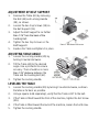
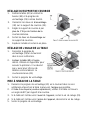
ADJUSTMENT OF BELT SUPPORT
1.
Remove the Table (40) by removing
the Bolt (45) and Locking Handle
(29), as shown.
2.
Loosen the two Cap Screws (38) on
the Belt Support (35).
3.
Adjust the Belt Support to no farther
than 1/16” from the back of the
Sanding Belt.
4.
Tighten the two Cap Screws on the
Belt Support.
5.
Replace the Table and tighten it in place.
ADJUSTING TABLE ANGLE
1.
Loosen the Locking Handle (29) by
turning it counterclockwise.
2.
Tilt the Table (40) to the desired
angle. Use a protractor to ensure
accuracy. There should be no more
than 1/16” distance between the
Table and the Sanding Belt (42).
3.
Tighten the Locking Handle.
LEVELING THE TABLE
1.
Loosen the Locking Handle (29) by turning it counterclockwise, and lean
the table as far back as possible.
2.
Using a square (sold separately), verify that the Table is 90° to the belt.
3.
If the Table is tilted toward the front of the machine, tighten the Set Screw
(39).
4.
If the Table is tilted toward the back of the machine, loosen the Set Screw.
5.
Tighten the Locking Handle.

WORKPIECE AND WORK AREA SET UP
1.
Designate a work area that is clean and well
-
lit. The work area must not
allow access by children or pets to prevent distraction and injury.
2.
Route the power cord along a safe route to reach the work area without
creating a tripping hazard or exposing the power cord to possible damage.
The power cord must reach the work area with enough extra length to
allow free movement while working.
3.
There must not be objects, such as utility lines, nearby that will present a
hazard while working.
GENERAL OPERATING INSTRUCTIONS
NOTICE! The Belt Sander is designed to sand only workpieces made of wood.
CAUTION! Do not sand stock that is too small to be safely supported or held.
Sand those pieces by hand.
1.
Plug Sander into wall socket (or extension cord) containing grounding
prong.
2.
Turn on Power Switch momentarily to verify that Sanding Belt is tracking
properly. If Belt tracking needs adjustment, turn Belt Sander off and refer
to Figure E. If the Sanding Belt is rotating properly with proper tracking, the
Belt Sander is ready for use.
3.
Turn on Power Switch.
4.
Push workpiece against belt gradually to start sanding. Keep hands clear
and do not apply excessive force.
CAUTION! Do not apply too much pressure on object being sanded that it
inhibits rotation of sanding belt. Keep fingers away from the sanding belt.
5.
To prevent accidents, turn off the tool and disconnect its power supply
after use. Clean, then store the tool indoors out of children’s reach.
MAINTENANCE AND SERVICING
WARNING! Procedures not specifically explained in this manual must be
performed only by a qualified technician.
WARNING! Turn the Power Switch of the tool off and unplug the tool from its
electrical outlet before performing any procedure in this section.

NOTICE! Do not use damaged equipment. If abnormal noise or vibration
occurs, have the problem corrected before further use.
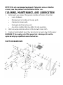
CLEANING, MAINTENANCE, AND LUBRICATION
1.
Before each use, inspect the general condition of the tool. Check for:
•
Loose hardware,
•
Misalignment or binding of moving parts,
•
Cracked or broken parts,
•
Damaged electrical wiring, and
•
Any other condition that may affect its safe operation.
2.
After use, wipe external surfaces of the tool with clean cloth.
3.
Replace Sanding Belts when they become torn or worn down to the paper.
WARNING! If the supply cord of this power tool is damaged, it must be
replaced only by a qualified service technician.
PARTS BREAKDOWN

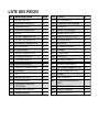
PARTS LIST
#
DESCRIPTION
QTY
1
Bolt M8 x 20
2
2
Spring Washer 8
2
3
Flat Washer 8
2
4
Rubber Feet
4
5
Base
1
6
Set Screw M6 x 10
2
7
Retaining Ring 15
2
8
Ball Bearing 6202
2
9
Driving Wheel
1
10
Driven Wheel
2
11
Countersunk Bolt M6 x 12
3
12
Lock Nut M10
1
13
Flat Washer 10
2
14
Frame
1
15
Pulley Axle B
1
16
Locking Handle
1
17
Spring A
1
18
Tracking Knob
1
19
Bolt M10 x 30
1
20
Spring Pin 3 x 18
1
21
Flat Washer 5
2
22
Spring B
1
23
Split Washer 4
1
24
Motor
1
25
Cushion
1
26
Spring C
1
27
Toothed Washer 8
1
28
Tension Axle
1
29
Locking Handle
1
30
Spring
1
31
Screw
1
32
Bolt M4 x 10
1
33
Flat Washer 4
1
34
Spark Guard
1
35
Belt Support
1
36
Flat Washer 4
2
37
Elastic Washer 4
2
38
Cap Screw M4 x 12
2
39
Set Screw M6 x 16
1
40
Table
1
41
Pulley Axle A
1
42
Sanding Belt 1 x 30
1
43
Side Guard
1
44
Guard Knob
1
45
Bolt M8 x 20
1

DISTRIBUTED BY
FORCOME (SHANGHAI) CO., LTD
SOUTH SIZHUAN ROAD,SHANGHAI 201612
MADE IN CHINA

Manuel d'utilisateur
9027251
Ponceuse à courroie de 1 po

SPÉCIFICATIONS
Courant électrique nominal
Environ 120 V/60 Hz / 2.1 A
Vitesse de la courroie
3,260 pi/min
Taille de courroie
1 x 30 po
Orifice antipoussières
D.E. de 1 3/4 po
SÉCURITÉ
AVERTISSEMENT ! Veuillez lire et comprendre toutes les instructions avant
d'utiliser cet outil. L'utilisateur doit respecter les précautions de base
lorsqu'il utilise cet outil afin de réduire le risque de blessure ou de
dommage à l'équipement.
Conservez ce manuel qui contient les avertissements de sécurité, les
précautions, les instructions de fonctionnement ou d'inspection et d'entretien.
DÉFINITIONS DE DANGER
Veuillez-vous familiariser avec les avis de danger qui sont présentés dans ce
manuel. Un avis est une alerte indiquant qu'il existe un risque de dommage à la
propriété, de blessure ou de décès si on ne respecte pas certaines instructions.
DANGER !
Cet avis indique un risque immédiat et particulier qui
entraînera des blessures corporelles graves ou même la
mort
si on omet de prendre les précautions nécessaires.
AVERTISSEMENT ! Cet avis indique un risque particulier ou une pratique non
sécuritaire qui
pourrait
entraîner des
blessures
corporelles graves ou même la mort
si on omet de
prendre les précautions nécessaires.
ATTENTION !
Cet avis indique une situation possiblement dangereuse qu

AVERTISSEMENTS DE SÉCURITÉ GÉNÉRAUX RELATIFS AUX OUTILS
1.
Laissez les protecteurs en place et en bon état de marche.
2.
Enlevez les clavettes et les clés de réglage. Habituez-vous à vérifier si les
clavettes et les clés de réglage ont été retirées de l’outil avant de le mettre
en marche.
3.
Gardez l’aire de travail propre. Les zones et les établis encombrés sont
propices aux accidents.
4.
Ne l’utilisez pas dans un environnement dangereux. N’utilisez pas d’outils
électriques dans un lieu humide ou mouillé et ne les exposez pas à la pluie.
Gardez l’aire de travail bien éclairée.
5.
Gardez les enfants éloignés. Tous les visiteurs devraient se tenir à une
distance sécuritaire de l’aire de travail.
6.
Rendez l’atelier à l’épreuve des enfants à l’aide de cadenas, d’interrupteurs
principaux ou en retirant les clés de démarrage.
7.
Ne forcez pas l’outil. Il fonctionnera mieux et sera plus sécurisé à la vitesse
pour laquelle il a été conçu.
8.
Utilisez l’outil recommandé. Ne forcez pas l’outil ou les accessoires à faire
un travail pour lequel ils n’ont pas été conçus.
TABLEAU A : CALIBRE DE FIL MINIMAL RECOMMANDÉ POUR LES RALLONGES
DE CÂBLE (120 V)
Nombre d’ampères figurant
sur la plaque signalétique
(à pleine charge)
Longueur de rallonge de câble
25 pi
50 pi
100 pi
150 pi
0 à 6
18
16
16
14
6,1 à 10
18
16
14
12

10,1 à 12
16
16
14
12
12,1 à 16
14
12
Ne l’utilisez pas.
9.
Utilisez une rallonge appropriée. Vérifiez que votre rallonge est en bon état.
Lors de l’utilisation d’une rallonge, assurez-vous qu’elle est conçue pour
transporter le courant électrique requis par votre produit. Un cordon de
calibre insuffisant entraînera une chute de tension causant une perte de
puissance et une surchauffe. Le tableau A indique le calibre correct à utiliser
en fonction de la longueur du cordon et des caractéristiques d’intensité de
courant figurant sur la plaque signalétique. En cas de doute, utilisez le
calibre supérieur. Plus le numéro du calibre est petit, plus le cordon est
robuste.
10.
Portez des vêtements appropriés. Ne portez pas de vêtements amples, de
gants, de cravates, de bagues ou des bijoux qui pourraient se coincer dans
les pièces mobiles. Des chaussures antidérapantes sont recommandées.
Portez un accessoire pour couvrir et protéger les cheveux afin de contenir
les cheveux longs.
11.
Portez toujours des lunettes de sécurité. Portez toujours un masque
protecteur ou antipoussières si le ponçage est poussiéreux. Les lunettes
ordinaires ne comprennent que des lentilles résistantes aux chocs, ce ne
sont pas des lunettes de sécurité.
12.
Évitez d’utiliser l’outil à bout de bras. Restez stable et en équilibre à tout
moment.
13.
Entretenez les outils avec soin. Gardez les outils propres pour obtenir un
meilleur rendement et une meilleure sécurité. Suivez les instructions pour
lubrifier et remplacer les accessoires.
14.
Débranchez les outils avant leur entretien ou avant de changer les
accessoires, tels que les courroies.
15.
Réduisez le risque de démarrage accidentel. Assurez-vous que l’interrupteur
est en position d’arrêt avant de brancher.
16.
Utilisez les accessoires recommandés. Consultez le manuel du propriétaire
pour connaître les accessoires recommandés. L’utilisation de mauvais
accessoires pourrait causer des blessures corporelles.
17.
Ne montez jamais sur l’outil. Des blessures graves pourraient se produire si
l’outil est basculé ou si la courroie est accidentellement touchée.

18.
Vérifiez les pièces endommagées. Avant de continuer l’utilisation de l’outil,
vérifiez minutieusement tout protecteur ou tout composant endommagé
afin de déterminer s’il fonctionne correctement et s’il permet d’exécuter la
fonction prévue – vérifiez l’alignement des pièces mobiles, le coincement
des pièces mobiles, le bris des pièces, le montage ou toute autre condition
qui pourrait affecter son fonctionnement. Une protection ou autre pièce qui
est endommagée devrait être réparée correctement ou remplacée.
19.
Direction d’insertion. Dirigez la pièce sur la courroie de façon opposée au
sens de rotation de la courroie seulement.
20.
Ne laissez jamais l’outil en marche sans surveillance. Coupez le courant. Ne
vous éloignez pas de l’outil jusqu’à ce qu’il soit immobilisé complètement.
INSTRUCTIONS POUR LA MISE À LA MASSE
DANGER! Pour prévenir toute décharge électrique et la mort en raison d’une
mauvaise connexion de fil de mise à la masse, lisez et suivez ces
instructions :
Outils mis à la masse de 110 à 120 V : Outils à fiche de connexion à trois
broches
1.
En cas de défaillance ou de panne, la mise à la masse fournit un chemin de
moindre résistance pour le courant électrique pour réduire le risque de
décharge électrique. Cet outil est équipé d’un cordon électrique muni d’un
conducteur de mise à la masse d’équipement et d’une fiche de mise à la
masse. La fiche doit être branchée dans une prise correspondante qui est
correctement installée et mise à la masse conformément à tous les codes et
à tous les règlements locaux.
2.
Ne modifiez pas la fiche fournie – si elle ne s’adapte pas à la prise;
demandez à un électricien qualifié d’installer la prise appropriée.
3.
Une connexion inadéquate du conducteur de mise à la masse de
l’équipement pourrait entraîner des risques de décharge électrique. Le
conducteur avec l’isolant dont la surface extérieure est verte avec ou sans
rayures jaunes est le conducteur de mise à la masse de l’équipement. Si la
réparation ou le remplacement du cordon électrique ou la fiche est
nécessaire, ne connectez pas le conducteur de mise à la masse
d’équipement à une borne sous tension.
La page est en cours de chargement...
La page est en cours de chargement...
La page est en cours de chargement...
La page est en cours de chargement...
La page est en cours de chargement...
La page est en cours de chargement...
La page est en cours de chargement...
La page est en cours de chargement...
La page est en cours de chargement...
La page est en cours de chargement...
La page est en cours de chargement...
La page est en cours de chargement...
-
 1
1
-
 2
2
-
 3
3
-
 4
4
-
 5
5
-
 6
6
-
 7
7
-
 8
8
-
 9
9
-
 10
10
-
 11
11
-
 12
12
-
 13
13
-
 14
14
-
 15
15
-
 16
16
-
 17
17
-
 18
18
-
 19
19
-
 20
20
-
 21
21
-
 22
22
-
 23
23
-
 24
24
-
 25
25
-
 26
26
-
 27
27
-
 28
28
-
 29
29
-
 30
30
-
 31
31
-
 32
32


X-POWER 9027251 Le manuel du propriétaire
- Taper
- Le manuel du propriétaire
dans d''autres langues
- English: X-POWER 9027251 Owner's manual
Autres documents
-
PROPOINT 9027988 Le manuel du propriétaire
-
General International BD7004 Manuel utilisateur
-
Skil 3375-01 Manuel utilisateur
-
Delta 31-482 Manuel utilisateur
-
-
Ryobi BD4601G Le manuel du propriétaire
-
Hitachi SB10Y1 - Power Tools Bench Top Belt Disc Sander Manuel utilisateur
-
-
Power Fist 8532293 Le manuel du propriétaire
-