ASROCK 939Dual-VSTA Guide d'installation
- Catégorie
- Cartes mères
- Taper
- Guide d'installation

11
11
1
ASRock 939Dual-VSTA Motherboard
EnglishEnglish
EnglishEnglish
English
Copyright Notice:Copyright Notice:
Copyright Notice:Copyright Notice:
Copyright Notice:
No part of this installation guide may be reproduced, transcribed, transmitted, or
translated in any language, in any form or by any means, except duplication of
documentation by the purchaser for backup purpose, without written consent of
ASRock Inc.
Products and corporate names appearing in this guide may or may not be registered
trademarks or copyrights of their respective companies, and are used only for
identification or explanation and to the owners’ benefit, without intent to infringe.
Disclaimer:Disclaimer:
Disclaimer:Disclaimer:
Disclaimer:
Specifications and information contained in this guide are furnished for informational
use only and subject to change without notice, and should not be constructed as a
commitment by ASRock. ASRock assumes no responsibility for any errors or
omissions that may appear in this guide.
With respect to the contents of this guide, ASRock does not provide warranty of any
kind, either expressed or implied, including but not limited to the implied warranties or
conditions of merchantability or fitness for a particular purpose.
In no event shall ASRock, its directors, officers, employees, or agents be liable for
any indirect, special, incidental, or consequential damages (including damages for
loss of profits, loss of business, loss of data, interruption of business and the like),
even if ASRock has been advised of the possibility of such damages arising from any
defect or error in the guide or product.
This device complies with Part 15 of the FCC Rules. Operation is subject to the
following two conditions:
(1) this device may not cause harmful interference, and
(2) this device must accept any interference received, including interference that
may cause undesired operation.
ASRock Website: http://www.asrock.com
Published June 2006
Copyright©2006 ASRock INC. All rights reserved.

22
22
2
ASRock 939Dual-VSTA Motherboard
EnglishEnglish
EnglishEnglish
English
Motherboard LMotherboard L
Motherboard LMotherboard L
Motherboard L
ayoutayout
ayoutayout
ayout
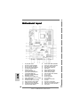
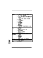
1 PS2_USB_PWR1 Jumper 18 Chassis Speaker Header (SPEAKER 1)
2 ATX Power Connector (ATXPWR1) 19 Chassis Fan Connector (CHA_FAN1)
3 CPU Fan Connector (CPU_FAN1) 20 Clear CMOS Jumper (CLRTC1)
4 ATX 12V Power Connector (ATX12V1) 21 USB 2.0 Header (USB45, Blue)
5 CPU Heatsink Retention Module 22 Flash Memory
6 939-Pin CPU Socket 23 Floppy Connector (FLOPPY1)
7 2 x 184-pin DDR DIMM Slots 24 Infrared Module Header (IR1)
(Dual Channel A: DDR1, DDR2; Blue) 25 Game Port Header (GAME1)
8 2 x 184-pin DDR DIMM Slots 26 Front Panel Audio Header (AUDIO1)
(Dual Channel B: DDR3, DDR4; Black) 27 JR1 / JL1 Jumper
9 North Bridge Controller 28 PCI Slots (PCI1- 3)
10 Serial ATAII Connector (SATAII_1, red) 29 AGP Slot (1.5V_AGP1)
11 JMicron JMB360 Chipset (PCIE x1 interface) 30 J9 / J10 Jumper
12 South Bridge Controller 31 PCI Express x1 Slot (PCIE2)
13 Secondary Serial ATA Connector (SATA2) 32 J11 Jumper
14 Primary Serial ATA Connector (SATA1) 33 PCI Express x16 Slot (PCIE1)
15 Primary IDE Connector (IDE1, Blue) 34 Future CPU Port (FUTURE_CPU_PORT1)
16 Secondary IDE Connector (IDE2, Black) 35 Internal Audio Connector: CD1 (Black)
17 System Panel Header (PANEL1) 36 J1-J8 Jumpers

33
33
3
ASRock 939Dual-VSTA Motherboard
EnglishEnglish
EnglishEnglish
English
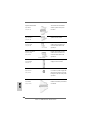
ASRock 8CH I/OASRock 8CH I/O
ASRock 8CH I/OASRock 8CH I/O
ASRock 8CH I/O
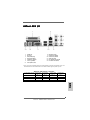
1 Parallel Port 8 Microphone (Pink)
2 RJ-45 Port 9 USB 2.0 Ports (USB01)
3 Side Speaker (Gray) 10 USB 2.0 Ports (USB23)
4 Rear Speaker (Black) 11 Serial Port: COM1
5 Central / Bass (Orange) 12 PS/2 Keyboard Port (Purple)
6 Line In (Light Blue) 13 PS/2 Mouse Port (Green)
*7 Front Speaker (Lime)
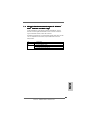
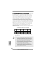
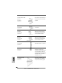
* If you use 2-channel speaker, please connect the speaker’s plug into “Front Speaker Jack”. See
the table below for connection details in accordance with the type of speaker you use.
TABLE for Audio Output Connection
Audio Output Channels Front Speaker Rear Speaker Central / Bass Side Speaker
(No. 7) (No. 4) (No. 5) (No. 3)
2 V -- -- --
4 V -- -- V
6V--VV
8 VVVV

44
44
4
ASRock 939Dual-VSTA Motherboard
1.1.
1.1.
1.
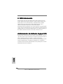
IntroductionIntroduction
IntroductionIntroduction
Introduction
Thank you for purchasing ASRock 939Dual-VSTA motherboard, a reliable
motherboard produced under ASRock’s consistently stringent quality control. It de-
livers excellent performance with robust design conforming to ASRock’s commit-
ment to quality and endurance.
This Quick Installation Guide contains introduction of the motherboard and step-by-
step installation guide. More detailed information of the motherboard can be found in
the user manual presented in the Support CD.
Because the motherboard specifications and the BIOS software might
be updated, the content of this manual will be subject to change without
notice. In case any modifications of this manual occur, the updated
version will be available on ASRock website without further notice. You
may find the latest VGA cards and CPU support lists on ASRock
website as well.
ASRock website http://www.asrock.com
1.11.1
1.11.1
1.1
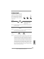
Package ContentsPackage Contents
Package ContentsPackage Contents
Package Contents
1 x ASRock 939Dual-VSTA Motherboard
(ATX Form Factor: 12.0-in x 9.6-in, 30.5 cm x 24.4 cm)
1 x ASRock 939Dual-VSTA Quick Installation Guide
1 x ASRock 939Dual-VSTA Support CD
1 x Ultra ATA 66/100/133 IDE Ribbon Cable (80-conductor)
1 x 3.5-in Floppy Drive Ribbon Cable
1 x Serial ATA (SATA) Data Cable (Optional)
1 x Serial ATA (SATA) HDD Power Cable (Optional)
1 x ASRock 8CH I/O Shield
EnglishEnglish
EnglishEnglish
English

55
55
5
ASRock 939Dual-VSTA Motherboard
EnglishEnglish
EnglishEnglish
English
1.21.2
1.21.2
1.2
SpecificationsSpecifications
SpecificationsSpecifications
Specifications
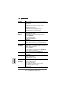
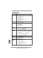
Platform - ATX Form Factor: 12.0-in x 9.6-in, 30.5 cm x 24.4 cm
CPU - Socket 939 for AMD Athlon
TM
64FX / 64X2 / 64 Processors
- Supports AMD’s Cool ‘n’ Quiet
TM
Technology
(see CAUTION 1)
- FSB 1000 MHz (2.0 GT/s)
- Supports Untied Overclocking Technology (see CAUTION 2)
- Supports Hyper-Transport Technology
Chipset - Northbridge: ULi
®
M1695
- Southbridge: ULi
®
M1567
Memory - Dual Channel DDR Memory Technology (see CAUTION 3)
- 4 x DDR DIMM slots
- Support DDR400/333/266
- Max. capacity: 4GB
Hybrid Booster - CPU Frequency Stepless Control (see CAUTION 4)
- ASRock U-COP (see CAUTION 5)
- Boot Failure Guard (B.F.G.)
Expansion Slot - 1 x Future CPU Port (Supports CPU upgrade from AMD K8
939-Pin CPU to AM2 940-Pin CPU through AM2CPU Board)
(see page 13 for details)
- 3 x PCI slots
- 1 x PCI Express x16 slot (see CAUTION 6)
- 1 x PCI Express x1 slot
- 1 x AGP 8X slot (see CAUTION 7)
Audio - C-Media CM6501 7.1 channel audio compliant with UAA
architecture
LAN - Realtek PHY RTL8201CL
- Speed: 10/100 Ethernet
- Supports Wake-On-LAN
Rear Panel I/O ASRock 8CH I/O
- 1 x PS/2 Mouse Port
- 1 x PS/2 Keyboard Port
- 1 x Serial Port: COM1
- 1 x Parallel Port (ECP/EPP Support)
- 4 x Ready-to-Use USB 2.0 Ports
- 1 x RJ-45 Port
- Audio Jack: Side Speaker/Rear Speaker/Central / Bass/
Line in/Front Speaker/Microphone (see CAUTION 8)

66
66
6
ASRock 939Dual-VSTA Motherboard
EnglishEnglish
EnglishEnglish
English
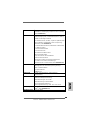
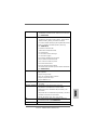
Connector - 2 x Serial ATA 1.5Gb/s connectors, support RAID (RAID 0,
RAID 1, JBOD) and “Hot Plug” functions
- 1 x Serial ATAII 3.0Gb/s connector by JMicron JMB 360
(PCIE x1 interface), supports NCQ, AHCI and “Hot Plug”
functions (see CAUTION 9)
- 2 x ATA133 IDE connectors (support 4 x IDE devices)
- 1 x Floppy connector
- 1 x IR header
- 1 x Game header
- CPU/Chassis FAN connector
- 20 pin ATX power connector
- 4 pin 12V power connector
- CD in header
- Front panel audio connector
- 1 x USB 2.0 headers (supports 2 USB 2.0 ports)
(see CAUTION 10)
BIOS Feature - 4Mb AMI BIOS
- AMI Legal BIOS
- Supports “Plug and Play”
- ACPI 1.1 Compliance Wake Up Events
- Supports jumperfree
- SMBIOS 2.3.1 Support
Support CD - Drivers, Utilities, AntiVirus Software (Trial Version)
Hardware - CPU Temperature Sensing
Monitor - Chassis Temperature Sensing
- CPU Fan Tachometer
- Chassis Fan Tachometer
- CPU Quiet Fan
- Voltage Monitoring: +12V, +5V, +3.3V, Vcore
OS - Microsoft
®
Windows
®
2000/XP/XP 64-bit/Vista
TM
compliant
(see CAUTION 11)
Certifications - FCC, CE, Microsoft
®
WHQL Certificated

77
77
7
ASRock 939Dual-VSTA Motherboard
CAUTION!
1. For power-saving’s sake, it is strongly recommended to enable AMD’s Cool ‘n’
Quiet
TM
technology under Windows system. See APPENDIX on page 45 of
“User Manual” in the support CD to enable AMD’s Cool ‘n’ Quiet
TM
technology.
Since not all K8 939-pin CPU can support AMD’s Cool ‘n’ Quiet
TM
technology,
please check AMD’s website for details.
2. This motherboard supports Untied Overclocking Technology. Please read
“Untied Overclocking Technology” on page 23 for details.
3. This motherboard supports Dual Channel Memory Technology. Before you
implement Dual Channel Memory Technology, make sure to read the
installation guide of memory modules on page 11 for proper installation.
4. Although this motherboard offers stepless control, it is not recommended to
perform over-clocking. Frequencies other than the recommended CPU bus
frequencies may cause the instability of the system or damage the CPU.
5. While CPU overheat is detected, the system will automatically shutdown.
Before you resume the system, please check if the CPU fan on the motherboard
functions properly and unplug the power cord, then plug it back again. To
improve heat dissipation, remember to spray thermal grease between the
CPU and the heatsink when you install the PC system.
6. For the information of the compatible PCI Express VGA cards, please
refer to the “Supported ATi X300 and X300SE Series PCI Express VGA
Card List for PCI Express Slot (PCI Express x16)” on page 9. For the
proper installation of PCI Express VGA card, please refer to the installation
guide on page 13.
7. Do NOT use a 3.3V AGP card on the AGP slot of this motherboard!
It may cause permanent damage!
8. For microphone input, this motherboard supports both stereo and mono modes.
For audio output, this motherboard supports 2-channel, 4-channel, 6-channel,
and 8-channel modes. Please check the table on page 3 for proper connection.
9. Before installing SATAII hard disk to SATAII connector, please read the “SATAII
Hard Disk Setup Guide” on page 19 to adjust your SATAII hard disk drive to
SATAII mode. You can also connect SATA hard disk to SATAII connector
directly.
10. Power Management for USB 2.0 works fine under Microsoft
®
Windows
®
Vista
TM
/ XP 64-bit / XP SP1 or SP2 / 2000 SP4.
11. Microsoft
®
Windows
®
Vista
TM
driver is not ready yet. We will update it to
our website in the future. Please visit our website for Microsoft
®
Windows
®
Vista
TM
driver and related information.
ASRock website http://www.asrock.com
EnglishEnglish
EnglishEnglish
English

88
88
8
ASRock 939Dual-VSTA Motherboard
EnglishEnglish
EnglishEnglish
English
1.31.3
1.31.3
1.3
Minimum Hardware RMinimum Hardware R
Minimum Hardware RMinimum Hardware R
Minimum Hardware R
equirement Tequirement T
equirement Tequirement T
equirement T
able for Wable for W
able for Wable for W
able for W
indowsindows
indowsindows
indows
®®
®®
®
VistaVista
VistaVista
Vista
TMTM
TMTM
TM
Premium and Basic Logo Premium and Basic Logo
Premium and Basic Logo Premium and Basic Logo
Premium and Basic Logo
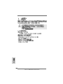
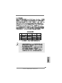
For system integrators and users who purchase this motherboard and
plan to submit Windows
®
Vista
TM
Premium and Basic logo, please follow the
below table for minimum hardware requirement. Please adopt the CPU,
memory, and VGA that we suggest.
CPU Athlon 3000+
Memory 512MB Single Channel
VGA DX9.0 with WDDM Driver
with 128bit VGA memory (Premium)
with 64bit VGA memory (Basic)

99
99
9
ASRock 939Dual-VSTA Motherboard
EnglishEnglish
EnglishEnglish
English
1.41.4
1.41.4
1.4
SupporSuppor
SupporSuppor
Suppor
ted Ated A
ted Ated A
ted A
Ti X300 and X300SE Series PCI ExpressTi X300 and X300SE Series PCI Express
Ti X300 and X300SE Series PCI ExpressTi X300 and X300SE Series PCI Express
Ti X300 and X300SE Series PCI Express
VGA Card List for PCI Express Slot (PCI Express x16)VGA Card List for PCI Express Slot (PCI Express x16)
VGA Card List for PCI Express Slot (PCI Express x16)VGA Card List for PCI Express Slot (PCI Express x16)
VGA Card List for PCI Express Slot (PCI Express x16)
(for Windows
®
2000/XP/XP 64-bit/Vista
TM
)
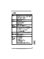
Since the margin of ATi X300 and X300SE series PCI Express VGA cards
may vary with different card vendors, we recommend users to adopt the
compatible ATi X300 and X300SE series cards below which have passed
our lab test.
Graphics Chip Model Name Chipset Name
Vendor
ATi ASUS EAX300/TD/128M/A RADEON X300
GIGABYTE GV-RX30128D RADEON X300
GECUBE RADEONR X300 PCIe 128MB RADEON X300
MSI RX300-TD128E RADEON X300
MSI RX300SE-TD128E RADEON X300SE

1010
1010
10
ASRock 939Dual-VSTA Motherboard
EnglishEnglish
EnglishEnglish
English
2.2.
2.2.
2.
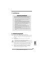
InstallationInstallation
InstallationInstallation
Installation
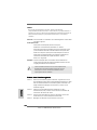
Pre-installation PrecautionsPre-installation Precautions
Pre-installation PrecautionsPre-installation Precautions
Pre-installation Precautions
Take note of the following precautions before you install mother-
board components or change any motherboard settings.
1. Unplug the power cord from the wall socket before touching any
component. Failure to do so may cause severe damage to the
motherboard, peripherals, and/or components.
2. To avoid damaging the motherboard components due to static
electricity, NEVER place your motherboard directly on the car-
pet or the like. Also remember to use a grounded wrist strap or
touch a safety grounded object before you handle components.
3. Hold components by the edges and do not touch the ICs.
4. Whenever you uninstall any component, place it on a
grounded antstatic pad or in the bag that comes with the
component.
5. When placing screws into the screw holes to secure the
motherboard to the chassis, please do not over-tighten the screws!
Doing so may damage the motherboard.
2.12.1
2.12.1
2.1
CPU InstallationCPU Installation
CPU InstallationCPU Installation
CPU Installation
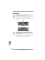
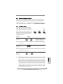
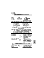
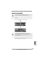
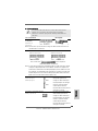
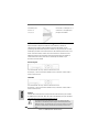
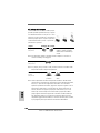
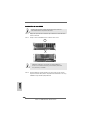
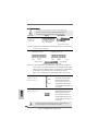
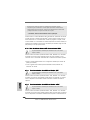
Step 1. Unlock the socket by lifting the lever up to a 90° angle.
Step 2. Position the CPU directly above the socket such that the CPU corner with
the golden triangle matches the socket corner with a small triangle.
Step 3. Carefully insert the CPU into the socket until it fits in place.
The CPU fits only in one correct orientation. DO NOT force the CPU
into the socket to avoid bending of the pins.
Step 4. When the CPU is in place, press it firmly on the socket while you push
down the socket lever to secure the CPU. The lever clicks on the side tab
to indicate that it is locked.
Step 5. Install CPU fan and heatsink. For proper installation, please kindly refer to
the instruction manuals of your CPU fan and heatsink vendors.

1111
1111
11
ASRock 939Dual-VSTA Motherboard
EnglishEnglish
EnglishEnglish
English
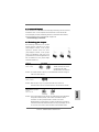
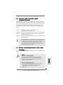
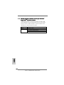
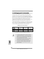
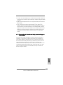
2.2 Installation of Memory Modules (DIMM)2.2 Installation of Memory Modules (DIMM)
2.2 Installation of Memory Modules (DIMM)2.2 Installation of Memory Modules (DIMM)
2.2 Installation of Memory Modules (DIMM)
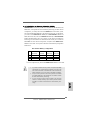
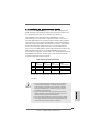
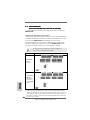
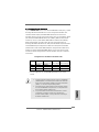
939Dual-VSTA motherboard provides four 184-pin DDR (Double Data Rate)
DIMM slots, and supports Dual Channel Memory Technology. For dual channel
configuration, you always need to install identical (the same brand, speed,
size and chip-type) DDR DIMM pair in the slots of the same color. In other words,
you have to install identical DDR DIMM pair in Dual Channel A (DDR1 and
DDR2; Blue slots; see p.2 No.7) or identical DDR DIMM pair in Dual Channel B
(DDR3 and DDR4; Black slots; see p.2 No.8), so that Dual Channel Memory
Technology can be activated. This motherboard also allows you to install four
DDR DIMMs for dual channel configuration, and please install identical DDR
DIMMs in all four slots. You may refer to the Dual Channel Memory Configuration
Table below.
Dual Channel Memory Configurations
DDR1 DDR2 DDR3 DDR4
(Blue Slot) (Blue Slot) (Black Slot) (Black Slot)
(1) Populated Populated - -
(2) - - Populated Populated
(3)* Populated Populated Populated Populated
* For the configuration (3), please install identical DDR DIMMs in all four slots.
1. If you want to install two memory modules, for optimal compatibility
and reliability, it is recommended to install them in the slots of the
same color. In other words, install them either in the set of blue slots
(DDR1 and DDR2), or in the set of black slots (DDR3 and DDR4).
2. If only one memory module or three memory modules are installed
in the DDR DIMM slots on this motherboard, it is unable to activate
the Dual Channel Memory Technology.
3. If a pair of memory modules is NOT installed in the same Dual
Channel, for example, installing a pair of memory modules in DDR1
and DDR3, it is unable to activate the Dual Channel Memory Tech-
nology .

1212
1212
12
ASRock 939Dual-VSTA Motherboard
EnglishEnglish
EnglishEnglish
English
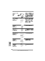
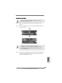
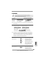
Installing a DIMMInstalling a DIMM
Installing a DIMMInstalling a DIMM
Installing a DIMM
Please make sure to disconnect power supply before adding or
removing DIMMs or the system components.
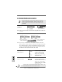
STEP 1: Unlock a DIMM slot by pressing the retaining clips outward.
STEP 2: Align a DIMM on the slot such that the notch on the DIMM matches the
break on the slot.
The DIMM only fits in one correct orientation. It will cause permanent
damage to the motherboard and the DIMM if you force the DIMM into the
slot at incorrect orientation.
STEP 3: Firmly insert the DIMM into the slot until the retaining clips at both ends
fully snap back in place and the DIMM is properly seated.

1313
1313
13
ASRock 939Dual-VSTA Motherboard
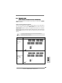
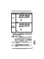
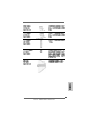
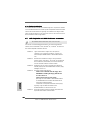
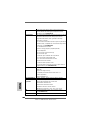
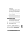
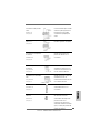
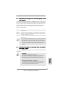
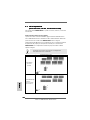
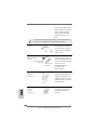
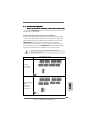
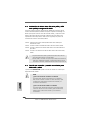
CPU Type Jumper Settings
939-Pin CPU
(Default)
AM2 940-Pin CPU
(Using add-on
ASRock AM2CPU
Board)
J1 J2
J3 J4
J5 J6
J7 J8
J11
J10
J9
J1 J2
J3 J4
J5 J6
J7 J8
J11
J10
J9
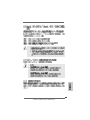
2.32.3
2.32.3
2.3
Expansion SlotsExpansion Slots
Expansion SlotsExpansion Slots
Expansion Slots
(Future CPU Port, PCI Slots, PCIE Slots, and AGP Slot)(Future CPU Port, PCI Slots, PCIE Slots, and AGP Slot)
(Future CPU Port, PCI Slots, PCIE Slots, and AGP Slot)(Future CPU Port, PCI Slots, PCIE Slots, and AGP Slot)
(Future CPU Port, PCI Slots, PCIE Slots, and AGP Slot)
There are 1 Future CPU Port, 3 PCI slots, 2 PCIE slots, and 1 AGP slot on 939Dual-
VSTA motherboard.
Future CPU Port (Yellow-Colored Port):
Future CPU Port allows you to upgrade your AMD K8 939-Pin CPU to AM2 940-Pin
CPU by installing an add-on ASRock AM2CPU Board into this future CPU Port on
939Dual-VSTA motherboard. Before you upgrade the K8 939-Pin CPU to AM2 940-
Pin CPU, it is necessary to adjust the jumper settings for those required jumpers on
939Dual-VSTA motherboard. Please refer to the table below for the correct jumper
settings.
This yellow-colored Future CPU Port is not an AGP slot! Please do
NOT insert any AGP card into it!
EnglishEnglish
EnglishEnglish
English

1414
1414
14
ASRock 939Dual-VSTA Motherboard
EnglishEnglish
EnglishEnglish
English
NOTE
When adjusting the jumper settings, you may use the tool, Jumper Cap Remover, to help you
removing the jumper caps more easily. This Jumper Cap Remover is bundled in your motherboard
package, and please follow the “Jumper Cap Remover Instruction” to use it properly.
PCI Slots: PCI slots are used to install expansion cards that have the 32-bit PCI
interface.
PCIE Slots: PCIE1 (PCIE x16 slot) is used for PCI Express cards with x16 lane
width graphics cards. For the information of the compatible PCI
Express VGA cards, please refer to the “Supported ATi X300 and
X300SE Series PCI Express VGA Card List for PCI Express Slot (PCI
Express x16)” on page 9.
PCIE2 (PCIE x1 slot) is used for PCI Express cards with x1 lane
width graphics cards, such as Gigabit LAN card, SATA2 card, etc.
AGP slot: The AGP slot is used to install a graphics card. The ASRock AGP slot has
a special design of clasp that can securely fasten the inserted graphics
card.
Please do NOT use a 3.3V AGP card on the AGP slot of this
motherboard! It may cause permanent damage! For the voltage infor-
mation of your AGP card, please check with the AGP card vendors.
Installing an expansion cardInstalling an expansion card
Installing an expansion cardInstalling an expansion card
Installing an expansion card
Step 1. Before installing the expansion card, please make sure that the power
supply is switched off or the power cord is unplugged. Please read the
documentation of the expansion card and make necessary hardware
settings for the card before you start the installation.
Step 2. Remove the system unit cover (if your motherboard is already installed in
a chassis).
Step 3. Remove the bracket facing the slot that you intend to use. Keep the
screws for later use.
Step 4. Align the card connector with the slot and press firmly until the card is
completely seated on the slot.
Step 5. Fasten the card to the chassis with screws.
Step 6. Replace the system cover.

1515
1515
15
ASRock 939Dual-VSTA Motherboard
EnglishEnglish
EnglishEnglish
English
2.52.5
2.52.5
2.5
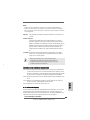
Jumpers SetupJumpers Setup
Jumpers SetupJumpers Setup
Jumpers Setup
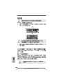
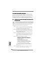
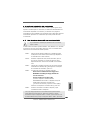
The illustration shows how jumpers are
setup. When the jumper cap is placed on
pins, the jumper is “Short”. If no jumper cap
is placed on pins, the jumper is “Open”. The
illustration shows a 3-pin jumper whose pin1
and pin2 are “Short” when jumper cap is
placed on these 2 pins.
Jumper Setting
PS2_USB_PWR1 Short pin2, pin3 to enable
(see p.2, No. 1) +5VSB (standby) for PS/2 or
USB wake up events.
Note: To select +5VSB, it requires 2 Amp and higher standby current provided by
power supply.
JR1 JL1 Jumper
(see p.2, No. 27)
Note: If the jumpers JL1 and JR1 are short, both the front panel and the rear panel
audio connectors can work.
Clear CMOS Jumper
(CLRTC1)
(see p.2, No. 20)
Note: CLRTC1 allows you to clear the data in CMOS. The data in CMOS includes
system setup information such as system password, date, time, and system
setup parameters. To clear and reset the system parameters to default setup,
please turn off the computer and unplug the power cord from the power
supply. After waiting for 15 seconds, use a jumper cap to short pin2 and pin3
on CLRTC1 for 5 seconds. However, please do not clear the CMOS right after
you update the BIOS. If you need to clear the CMOS when you just finish
updating the BIOS, you must boot up the system first, and then shut it down
before you do the clear-CMOS action.
2.42.4
2.42.4
2.4
Surround Display FeatureSurround Display Feature
Surround Display FeatureSurround Display Feature
Surround Display Feature
This motherboard supports Surround Display upgrade. With the external add-on
AGP VGA card and PCI Express VGA card, you can easily enjoy the benefits of
Surround Display feature. For the detailed instruction, please refer to the docu-
ment at the following path in the Support CD: ..\ Surround Display Information
Short Open
Clear CMOSDefault

1616
1616
16
ASRock 939Dual-VSTA Motherboard
EnglishEnglish
EnglishEnglish
English
the red-striped side to Pin1
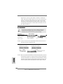
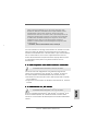
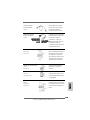
2.6 Onboard Headers and Connectors2.6 Onboard Headers and Connectors
2.6 Onboard Headers and Connectors2.6 Onboard Headers and Connectors
2.6 Onboard Headers and Connectors
Onboard headers and connectors are NOT jumpers. Do NOT place
jumper caps over these headers and connectors. Placing jumper caps
over the headers and connectors will cause permanent damage of the
motherboard!
•
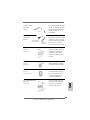
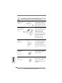
Floppy Connector
(33-pin FLOPPY1)
(see p.2 No. 23)
Note: Make sure the red-striped side of the cable is plugged into Pin1 side of the
connector.
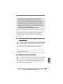
Primary IDE Connector (Blue) Secondary IDE Connector (Black)
(39-pin IDE1, see p.2 No. 15) (39-pin IDE2, see p.2 No. 16)
Note: If you use only one IDE device on this motherboard, please set the IDE
device as “Master”. Please refer to the instruction of your IDE device vendor
for the details. Besides, to optimize compatibility and performance, please
connect your hard disk drive to the primary IDE connector (IDE1, blue) and
CD-ROM to the secondary IDE connector (IDE2, black).
Serial ATA Connectors (Black) These two Serial ATA (SATA)
(SATA1: see p.2 No. 14) connectors support SATA data
(SATA2: see p.2 No. 13) cables for internal storage
devices. The current SATA
interface allows up to 1.5 Gb/s
data transfer rate.
It is recommended to plug SATAII HDD to SATAII connector (SATAII_1) and
connect SATA HDD to SATA connector (SATA1 or SATA2).
Serial ATA II Connector (Red) This Serial ATA II (SATA II)
(SATA II_1: see p.2 No. 10) connector supports SATA
data cables for internal storage
devices. The current SATAII
interface allows up to 3.0 Gb/s
data transfer rate.
SATA II_1
SATA1
SATA2
connect the black end
to the IDE devices
connect the blue end
to the motherboard
80-conductor ATA 66/100/133 cable

1717
1717
17
ASRock 939Dual-VSTA Motherboard
EnglishEnglish
EnglishEnglish
English
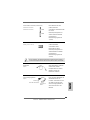
Serial ATA (SATA) Please connect the black end of
Power Cable SATA power cable to the power
(Optional) connector on each drive. Then
connect the white end of SATA
power cable to the power
connector of the power supply.
USB 2.0 Header Besides four default USB 2.0
(9-pin USB45) ports on the I/O panel, there is
(see p.2 No. 21) one USB 2.0 header on this
motherboard. This USB 2.0
header cansupport two USB
2.0 ports.
Infrared Module Header This header supports an
(5-pin IR1) optional wireless transmitting
(see p.2 No. 24) and receiving infrared module.
Internal Audio Connectors This connector allows you
(4-pin CD1) to receive stereo audio input
(CD1: see p.2 No. 35) from sound sources such as
a CD-ROM, DVD-ROM, TV
tuner card, or MPEG card.
Front Panel Audio Header This is an interface for front
(8-pin AUDIO1) panel audio cable that allows
(see p.2 No. 26) convenient connection and
control of audio devices.
Serial ATA (SATA) Either end of the SATA data cable
Data Cable can be connected to the SATA /
(Optional) SATAII hard disk or the SATA /
SATAII connector on the
motherboard.
CD1
connect to the
power supply
connect to the SATA
HDD power connector

1818
1818
18
ASRock 939Dual-VSTA Motherboard
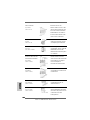
System Panel Header This header accommodates
(9-pin PANEL1) several system front panel
(see p.2 No. 17) functions.
Chassis Speaker Header Please connect the chassis
(4-pin SPEAKER 1) speaker to this header.
(see p.2 No. 18)
Chassis Fan Connector Please connect a chassis fan
(3-pin CHA_FAN1) cable to this connector and
(see p.2 No. 19) match the black wire to the
ground pin.
CPU Fan Connector Please connect the CPU fan
(4-pin CPU_FAN1) cable to this connector and
(see p.2 No. 3) match the black wire to the
ground pin.
ATX Power Connector Please connect an ATX power
(20-pin ATXPWR1) supply to this connector.
(see p.2 No. 2)
ATX 12V Power Connector Please note that it is necessary
(4-pin ATX12V1) to connect a power supply with
(see p.2 No. 4) ATX 12V plug to this connector.
Failing to do so will cause power
up failure.
Game Port Header Connect a Game cable to this
(15-pin GAME1) header if the Game port bracket
(see p.2 No. 25) is installed.
EnglishEnglish
EnglishEnglish
English

1919
1919
19
ASRock 939Dual-VSTA Motherboard
EnglishEnglish
EnglishEnglish
English
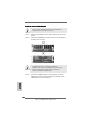
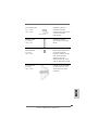
The above examples are just for your reference. For different SATAII hard
disk products of different vendors, the jumper pin setting methods may not
be the same. Please visit the vendors’ website for the updates.
2.72.7
2.72.7
2.7
SASA
SASA
SA
TT
TT
T
AII Hard Disk Setup GuideAII Hard Disk Setup Guide
AII Hard Disk Setup GuideAII Hard Disk Setup Guide
AII Hard Disk Setup Guide
Before installing SATAII hard disk to your computer, please carefully read below
SATAII hard disk setup guide. Some default setting of SATAII hard disks may not
be at SATAII mode, which operate with the best performance. In order to enable
SATAII function, please follow the below instruction with different vendors to
correctly adjust your SATAII hard disk to SATAII mode in advance; otherwise, your
SATAII hard disk may fail to run at SATAII mode.
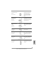
Western Digital
If pin 5 and pin 6 are shorted, SATA 1.5Gb/s will be enabled.
On the other hand, if you want to enable SATAII 3.0Gb/s, please remove the
jumpers from pin 5 and pin 6.
SAMSUNG
If pin 3 and pin 4 are shorted, SATA 1.5Gb/s will be enabled.
On the other hand, if you want to enable SATAII 3.0Gb/s, please remove the
jumpers from pin 3 and pin 4.
HITACHI
Please use the Feature Tool, a DOS-bootable tool, for changing various ATA
features. Please visit HITACHI’s website for details:
http://www.hitachigst.com/hdd/support/download.htm

2020
2020
20
ASRock 939Dual-VSTA Motherboard
2.82.8
2.82.8
2.8
Serial ASerial A
Serial ASerial A
Serial A
TT
TT
T
A (SAA (SA
A (SAA (SA
A (SA
TT
TT
T
A) / Serial AA) / Serial A
A) / Serial AA) / Serial A
A) / Serial A
TT
TT
T
AII (SAAII (SA
AII (SAAII (SA
AII (SA
TT
TT
T
AII) Hard DisksAII) Hard Disks
AII) Hard DisksAII) Hard Disks
AII) Hard Disks
InstallationInstallation
InstallationInstallation
Installation
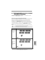
This motherboard adopts JMicron JMB360 chipset that supports Serial ATAII
(SATAII) hard disk. It also adopts ULi
®
M1567 south bridge chipset that supports
Serial ATA (SATA) hard disks, and supports RAID functions. You may install SATA /
SATAII hard disks on this motherboard for internal storage devices. This section
will guide you to install the SATA / SATAII hard disks.
STEP 1: Install the SATA / SATAII hard disks into the drive bays of your chassis.
STEP 2: Connect the SATA power cable to the SATA / SATAII hard disk.
STEP 3: Connect one end of the SATA data cable to the motherboard’s SATA /
SATAII connector.
STEP 4: Connect the other end of the SATA data cable to the SATA / SATAII hard
disk.
1. If you plan to use RAID 0, RAID 1, or JBOD functions on SATA, SATA
HDDs must be operated in “RAID” mode.
2. “RAID” and “non-RAID” mode are options under “SATA Operation Mode” in
BIOS setup. Please refer to page 35 of “User Manual” in the support CD
for details. They need different drivers during actual operation.
2.9 Hot Plug and Hot Swap F2.9 Hot Plug and Hot Swap F
2.9 Hot Plug and Hot Swap F2.9 Hot Plug and Hot Swap F
2.9 Hot Plug and Hot Swap F
unctions for SAunctions for SA
unctions for SAunctions for SA
unctions for SA
TT
TT
T
A / SAA / SA
A / SAA / SA
A / SA
TT
TT
T
AIIAII
AIIAII
AII
HDDsHDDs
HDDsHDDs
HDDs
939Dual-VSTA motherboard supports Hot Plug and Hot Swap functions for SATA /
SATAII Devices.
NOTE
What is Hot Plug Function?
If the SATA / SATAII HDDs are NOT set for RAID configuration, it is called
“Hot Plug” for the action to insert and remove the SATA / SATAII HDDs
while the system is still power-on and in working condition.
However, please note that it cannot perform Hot Plug if the OS has been
installed into the SATA / SATAII HDD.
What is Hot Swap Function?
If SATA / SATAII HDDs are built as RAID1 then it is called “Hot Swap” for
the action to insert and remove the SATA / SATAII HDDs while the system
is still power-on and in working condition.
EnglishEnglish
EnglishEnglish
English
La page est en cours de chargement...
La page est en cours de chargement...
La page est en cours de chargement...
La page est en cours de chargement...
La page est en cours de chargement...
La page est en cours de chargement...
La page est en cours de chargement...
La page est en cours de chargement...
La page est en cours de chargement...
La page est en cours de chargement...
La page est en cours de chargement...
La page est en cours de chargement...
La page est en cours de chargement...
La page est en cours de chargement...
La page est en cours de chargement...
La page est en cours de chargement...
La page est en cours de chargement...
La page est en cours de chargement...
La page est en cours de chargement...
La page est en cours de chargement...
La page est en cours de chargement...
La page est en cours de chargement...
La page est en cours de chargement...
La page est en cours de chargement...
La page est en cours de chargement...
La page est en cours de chargement...
La page est en cours de chargement...
La page est en cours de chargement...
La page est en cours de chargement...
La page est en cours de chargement...
La page est en cours de chargement...
La page est en cours de chargement...
La page est en cours de chargement...
La page est en cours de chargement...
La page est en cours de chargement...
La page est en cours de chargement...
La page est en cours de chargement...
La page est en cours de chargement...
La page est en cours de chargement...
La page est en cours de chargement...
La page est en cours de chargement...
La page est en cours de chargement...
La page est en cours de chargement...
La page est en cours de chargement...
La page est en cours de chargement...
La page est en cours de chargement...
La page est en cours de chargement...
La page est en cours de chargement...
La page est en cours de chargement...
La page est en cours de chargement...
La page est en cours de chargement...
La page est en cours de chargement...
La page est en cours de chargement...
La page est en cours de chargement...
La page est en cours de chargement...
La page est en cours de chargement...
La page est en cours de chargement...
La page est en cours de chargement...
La page est en cours de chargement...
La page est en cours de chargement...
La page est en cours de chargement...
La page est en cours de chargement...
La page est en cours de chargement...
La page est en cours de chargement...
La page est en cours de chargement...
La page est en cours de chargement...
La page est en cours de chargement...
La page est en cours de chargement...
La page est en cours de chargement...
La page est en cours de chargement...
La page est en cours de chargement...
La page est en cours de chargement...
La page est en cours de chargement...
La page est en cours de chargement...
La page est en cours de chargement...
La page est en cours de chargement...
La page est en cours de chargement...
La page est en cours de chargement...
La page est en cours de chargement...
La page est en cours de chargement...
La page est en cours de chargement...
La page est en cours de chargement...
La page est en cours de chargement...
La page est en cours de chargement...
La page est en cours de chargement...
La page est en cours de chargement...
La page est en cours de chargement...
La page est en cours de chargement...
La page est en cours de chargement...
La page est en cours de chargement...
La page est en cours de chargement...
La page est en cours de chargement...
La page est en cours de chargement...
La page est en cours de chargement...
La page est en cours de chargement...
La page est en cours de chargement...
La page est en cours de chargement...
La page est en cours de chargement...
La page est en cours de chargement...
La page est en cours de chargement...
La page est en cours de chargement...
La page est en cours de chargement...
La page est en cours de chargement...
La page est en cours de chargement...
La page est en cours de chargement...
La page est en cours de chargement...
La page est en cours de chargement...
La page est en cours de chargement...
-
 1
1
-
 2
2
-
 3
3
-
 4
4
-
 5
5
-
 6
6
-
 7
7
-
 8
8
-
 9
9
-
 10
10
-
 11
11
-
 12
12
-
 13
13
-
 14
14
-
 15
15
-
 16
16
-
 17
17
-
 18
18
-
 19
19
-
 20
20
-
 21
21
-
 22
22
-
 23
23
-
 24
24
-
 25
25
-
 26
26
-
 27
27
-
 28
28
-
 29
29
-
 30
30
-
 31
31
-
 32
32
-
 33
33
-
 34
34
-
 35
35
-
 36
36
-
 37
37
-
 38
38
-
 39
39
-
 40
40
-
 41
41
-
 42
42
-
 43
43
-
 44
44
-
 45
45
-
 46
46
-
 47
47
-
 48
48
-
 49
49
-
 50
50
-
 51
51
-
 52
52
-
 53
53
-
 54
54
-
 55
55
-
 56
56
-
 57
57
-
 58
58
-
 59
59
-
 60
60
-
 61
61
-
 62
62
-
 63
63
-
 64
64
-
 65
65
-
 66
66
-
 67
67
-
 68
68
-
 69
69
-
 70
70
-
 71
71
-
 72
72
-
 73
73
-
 74
74
-
 75
75
-
 76
76
-
 77
77
-
 78
78
-
 79
79
-
 80
80
-
 81
81
-
 82
82
-
 83
83
-
 84
84
-
 85
85
-
 86
86
-
 87
87
-
 88
88
-
 89
89
-
 90
90
-
 91
91
-
 92
92
-
 93
93
-
 94
94
-
 95
95
-
 96
96
-
 97
97
-
 98
98
-
 99
99
-
 100
100
-
 101
101
-
 102
102
-
 103
103
-
 104
104
-
 105
105
-
 106
106
-
 107
107
-
 108
108
-
 109
109
-
 110
110
-
 111
111
-
 112
112
-
 113
113
-
 114
114
-
 115
115
-
 116
116
-
 117
117
-
 118
118
-
 119
119
-
 120
120
-
 121
121
-
 122
122
-
 123
123
-
 124
124
-
 125
125
-
 126
126
-
 127
127
-
 128
128


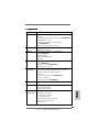
ASROCK 939Dual-VSTA Guide d'installation
- Catégorie
- Cartes mères
- Taper
- Guide d'installation
dans d''autres langues
Documents connexes
-
ASROCK 939Dual-VSTA Le manuel du propriétaire
-
ASROCK 939NF4G-SATA2 Le manuel du propriétaire
-
ASROCK P4V88+ Le manuel du propriétaire
-
ASROCK K8UPGRADE-VM800 Le manuel du propriétaire
-
ASROCK 939S56-M Le manuel du propriétaire
-
ASROCK K7NF2-RAID Le manuel du propriétaire
-
ASROCK 775V88 Le manuel du propriétaire
-
ASROCK K7UPGRADE-600 Le manuel du propriétaire
-
ASROCK K7VT4A PRO Le manuel du propriétaire
-
ASROCK ALIVENF6P-VSTA Le manuel du propriétaire