
CAMERAS IP 100 SERIES
Please read this manual thoroughly before use and keep it for future reference

Statement
The instruction is for guidance only. Detailed information is in accordance with the product.
The instruction may include some technical inaccuracies or typographical error thought it is prepared with
our every effort.
The product or procedures described in the instruction may be changed or updated at any time without
advance notice.
Screenshots used in the instruction are only for indications and explanations.
For any doubts or to request documents about latest procedures and complementary notes, please
consult with the after-sales service department..
Precautions
The followings describe information about correct usage and risk prevention as well property loss
prevention to be strictly followed.
Please use web cameras in an environment within allowable temperature and humidity.
Check if the power supply works normally before operation.
Do not furiously strike on the product and be careful not to fall it over.
Do not install the product in a dusty or moist place, or a place with strong electromagnetic radiation.
Do not place a container or others with liquid on the product or allow liquid flowing into inside the product.
When the product is left unused, place install the preventive dust cover for the image sensor.
Do not disassemble the product without authorization.

1
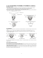
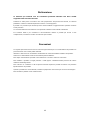
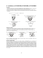
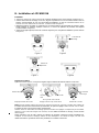
A. Art. IPCAM1838A, IPCAM1848A, IPCAM184KA installation
Mounting the camera
1.Take out the camera and installation accessories from inside the box, install the template sticker in
order to make the holes properly. Open the camera and fix it using the plugs (Figure 1).
2.Tear off the lens protective film and adjust the camera angle (Figure 2 and 3).
3.Follow the instruction lens adjustment and desiccant placement instruction, close the camera and lock
the screws to complete the installation (Figure 4).
75° 75°
Figure 1 Figure 2
75°
Figure 3 Figure 4
Lens adjustment
1.Rotate the 3D stand, which can rotate in the horizontal direction, the rotation angle is around 75° each
side
2.Loose the screw 1, which can be adjusted in the vertical direction, the adjustable range is 0~75°
3.Loose the screw 2, rotation adjustament, restricted by the internal connector, we suggest no more
than 30° rotation angle
75° 75° Screw 1
3D stand 75°
0°
Horizontal adjustment Vertical adjustment Rotation adjustment
For vertical wall installation use the "Mirror" function, in "Video parameters" of the camera, to have a
straight image.
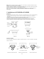
Desiccant placement instructions:
After installing the camera to adjust the direction of monitoring, remove the desiccant from the box and
insert it as showed in the picture (desiccant placement)
Due to different temperature between inside and outside the housing, may there be moisture inside the
camera when switch on for the first time. Please power off the camera until the desiccant absorbs the
moisture and than switch on again.
The desiccant may not be effective if the camera has been left opened during installation more than 1
hour, in this case please replace the desiccant.
Screw 2
Ceiling or wall
Install the stickers
0°

2
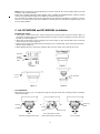
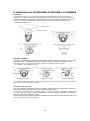
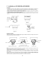
B. Art. IPCAM133A installation
Mounting the camera
1. Take out the camera from the box and rotate the upper cover to open it (as shown in figure 1).
2. Paste the mounting sticker to the wall, align the hole position of camera lower cover with the
corresponding position of installation sticker hole, and fix the camera lower cover to the wall using the
accessories (as shown in figure 2).
3. Adjust position of the housing body to ensure that the camera reaches the requirements of users,
adjust the angle (lens adjustment, explained below) and remove the lens protection film (as shown in
figure 3).
4. After adjusting the lens, close the upper cover to complete the installation (as shown in figure 4).
Figure 1 Figure 2
Figure 3 Figure 4
Lens adjustment
After fixing the camera, you can adjust the angle by using the three-axis mounting bracket, horizontal,
vertical and rotation.
320° 60° for left and 50° for right 360°
Horizontal adjustment for bracket Vertical adjustment for dome body Camera rotation
Desiccant placement
Mounting
stickers
Lens protective
film
Bracket rotation
60°
50°
Dome
body
Bracket
screw
Fixing ring
screw

3
Note: When the dome body vertical adjusting is set to 60° to the left, the camera rotation limit is 20° both
clockwise and counterclockwise.
Follow the mounting instruction when regulate, don’t overtake the regulation limits. If the IR Led are
covered, they will reflect the light on the image as showed in the picture.
Be careful with the bubble. Remove the protective film just when the installation is complete. If need to
clean it, use an anti-scratch cloth. If the bubble is scratched, the leds will reflect the light and may cause
issue in night condition.
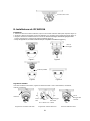
C. Art. IPCAM183B and IPCAM185B installation
Mounting the camera
1. Take out the camera from the box, use the hexagon wrench to loose the screws (as shown in figure 1),
remove the mounting plate, paste mounting sticker to the wall, and use mounting accessories to fix it to
the wall (as shown in figure 1).
2. Mount the camera lower cover by rotating it (as shown in figure 2), than lock the little screw on the side
of the camera (as shown in figure 3).
3. Adjust camera angle (lens adjustment) according to user's requirements. Than remove the protection
film (as shown in figure 4).
4. After adjusting the lens, remove the protective film, close the upper cover and lock the screw.
Figure 1 Figure 2
Figure 3 Figure 4
Lens adjustment
After fixing the camera, you can adjust the angle by using the three-axis mounting bracket, horizontal,
vertical and rotation.
360° 50° for left and 80° for right 360°
Horizontal adjustment for bracket Vertical adjustment for dome body Camera rotation
Bracket
(rotatable)
50°
80°
Dome
body
Bracket screw
Mounting
plate
Mounting
stickers
Hexagon
wrench
Lens protective
film
Fixing ring
screw

4
Note: when the dome body vertical adjusting is set 80° to the right, the rotation regulation limit is 30° both
clockwise and counterclockwise.
Follow the mounting instruction when regulate, don’t overtake the regulation limits. If the IR Led are
covered, they will reflect the light on the image as showed in the picture.
Be careful with the bubble. Remove the protective film just when the installation is complete. If need to
clean it, use an anti-scratch cloth. If the bubble is scratched, the leds will reflect the light and may cause
issue in night condition.
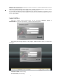
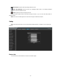
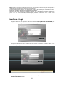
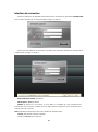
Login Interface
Input the IP address of the front-end device into the IE browser (default IP address is
192.168.1.188) to access the Login interface, as shown in the following figure:
After entering into the login interface, it will prompt to install the Activex control, as shown in the
follow figure:
User Name: admin (default setting)
Password: blank (default setting)

5
Model: IE ActiveX or Non ActiveX. If you use IE browser, then please select IE ActiveX to login.
While you use other browsers, then select Non ActiveX to login.
Note: Select Non ActiveX without installing Activex control
Select Language: select the desired language
Click Submit to login.
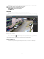
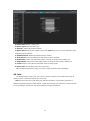
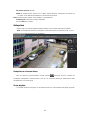
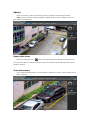
Live view
After login, it will enter into the live preview, as shown in the follow figure.
Note: the inserted micro-SD card is for full function display interface, otherwise, it's for simple type
interface.
Full-screen Preview
Click the full-screen icon in the lower right corner to preview full screen, or you can click
right mouse button to enter and exit the full screen display in the preview interface.
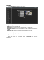
Electronic Zoom-in
It can zoom in the preview image by scrolling the mouse wheel, as shown in the follow figure:

6
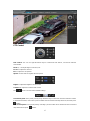
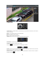
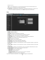
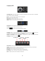
PTZ Control
PTZ Control: You can use eight directional keys to rotate front-end devices, and AUTO indicates
auto-rotation.
Zoom +/ - : To adjust degree of zoom in/ out
Focus: To adjust size of focus
Iris: To adjust size of aperture
Speed: Use the slider to regulate the PTZ speed
Bright: To adjust the brightness of the screen
Contrast: To adjust the contrast of the screen
The arrow is used to restore default settings.
Set a Preset point: Set a preset point by using directional keys on the PTZ control to rotate the camera
to the desired location, next select a preset number from the Preset Point drop-down list, and then press
button.
Call a Preset point: Call a preset point by selecting a preset number to be called from the Preset Point
drop-down list and press button.

7
Voice Intercom: Click it to enable or disable voice intercom
Capture: Capture for preview. Click the capture icon, it will pop up its storage path automatically.
Full Screen: Display the current preview in full screen
Record: Enable or disable preview interface record
Event Type: Enable or disable disarming/ clear alarm
Note: X indicates the function is off or disabled
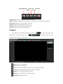
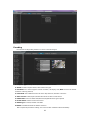
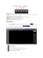
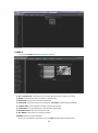
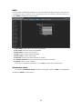
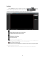
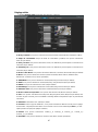
Playback
Click Playback enter into playback interface, click the icon , next select the date time of the
calling video in need, then click the icon , the record video will search
automatically, as shown in the follow figure:
Start: Start the current playback
Stop: Stop the current playback
Slow: Slow down the playback speed (1/2, 1/4, 1/8, 1/16 times optional)
Fast: Speed up the playback speed (2, 4, 8, 16 times optional)
Capture: Can be capture in playback channel
Backup: Can be backup video in playback channel
Frame Play: Single frame to play
VOICE INTERCOM
Capture
Full Screen
Record
Event Type

8
Full Screen: Playback video will display with full screen
Show smart detection: when the video is to intelligent detect video, it can display intelligent
Detection rules and statistical result.
Voice: Adjust the volume of playback audio
Double-click the slider location, it will start to play the video, or you can click the Start button to
playback video.
Note: The device should support micro-SD card storage to enable this function
Setup
Note: the inserted micro-SD card is for full function display interface, otherwise, it's for simple type
interface.
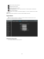
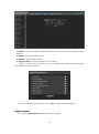
Device Info
IP Camera Device Info interface as shown in the follow figure:

9
Device Name: Edit the camera name
Device Type: Display the device type
Serial No. : Display the product serial No.
Master Version: Display the software version date (Note: Based on the version information which
displayed in factory product)
Hardware Version: Display the hardware version number
Audio Source: Select the audio input mode, LineIn or MicIn selectable
Input Volume: Set the size of the input volume, the range of volume:0-100, default is 50
Output Volume: Set the size of the output volume, the range of volume:0-100, default is 50
Format: Switch to select the PAL and NTSC image scanning system
Device Time: Set and display the device current time
After complete all parameters setting, click Save and then it will take effect immediately.
QR Code
The display interface of QR code of IP Camera is shown as below. Use Comelit View 100 app to
directly scan the Comelit View 100 ID QR code to login.
Note: the Device ID QR icon will display only after the opening the corresponding agreement in
platform management interface and it supports Comelit View 100 QR code at present:. Comelit View 100
is corresponding to Comelit View 100 client in platform management interface.

10
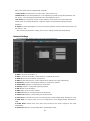
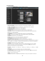
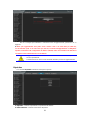
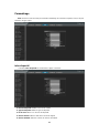
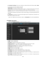
Encoding
IP Camera Encoding setting interface as shown in the follow figure:
Compress Type: Primary Stream(Normal)/ Sub Stream selectable
Stream: Include complex stream/ video stream two types
Resolution: The camera supports several resolution , will display here (Note: based on the default
resolution of factory products)
Frame Rate: Select different frame rate in the drop-down list, default is Full Frame
Video Encode: H.264/ MJPEG/H.264+ three kinds of video encode format
H264 Profile: There are MainProfile/ Baseline/ HighProfile three types optional
I frame Interval: Set the I frame interval size
Bitrate Type: Constant/ Variable selectable
Bitrate: Set different bitrate for different channels
After complete all parameters setting, click Save and then it will take effect immediately.

11
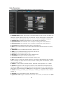
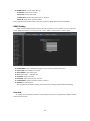
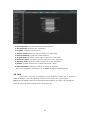
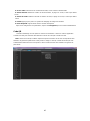
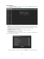
Video Parameters
IP Camera Video Parameters setting interface as shown in the follow figure:
Day&Night Mode: Outside Trigger/ Auto/ Color/ Black White four kinds of mode selectable. Non
infrared IP cameras default mode is Auto, and infrared IP cameras default mode is Outside Trigger.
According to the IP camera type and actual scene, user can select the Day&Night mode optional
Switching Time: Day&Night switch delay time, 0-30s selectable, and default is 3s
Day-Ni-Threshold: 0-255 selectable, users can adjust it according to the need, default is 20
Ni-Day-Threshold: 0-255 selectable, users can adjust it according to the need, default is 35
Color Mode: Normal/ Bright/ Nature three options, default is Normal
Mirror: Close/ Horizonal Mirror/ Vertical Mirror/ 180 Rotation/90 Rotation/270 Rotation six options,
default is Close
TWDR/WDR: Close/ Low/ Mid/ High four options, default is Close
3DNR: Close/ Low/ Mid/ Mid-High/ High five levels, default is Low
Sharpness: 0-255 selectable, default is 128
Defogging: Close/ Low/ Mid/ High four options, default is Close.
Slow Shutter: Close/Open selectable, default is Close.
Exposure Control Mode: Auto/ Manual selectable, default is Auto
AGC: It can be set when it's automatic exposure, Low/ Mid-Low/ Mid/ Mid-High/ High selectable,
default is Mid-High. The higher Auto Gain value, the better sensitivity within low illumination, while the
noise will be more obvious
Shutter: It can be set when it's manual exposure, the shutter value range:1/30(25)-1/10000
Aperture:According to the IPC lens type, the aperture can be divided into manual aperture and
auto aperture (Note: based on the default aperture of factory products), the lens can be divided into
manual focus and semiautomatic focus (Note: there is this option when it's equipped with electric lens)
Gamma: CURVE_1_6, CURVE_1_8, CURVE_2_0, CURVE_2_2 totally four modes, default is
CURVE_2_0
Anti-Fliker: Close, 50hz, 60hz three types, the default is Close
Light board control: 3 types of led board control mode: close, manual, auto. Default to auto. (Note:

12
there is this option when it's equipped with Smart IR)
Closing mode: The led board can not be control, and it always close.
Manual mode: The led board brightness can be adjusted by manually change the parameters, and
the range is 1-100, the higher the parameter value, the brighter the IR led.
Auto mode: The image of the camera can be optimum, and it's power can be the minimum by
acquiring the current image brightness & exposure & gain, and dynamically adjusting the light
brightness.
Bright: The led board brightness can be set when the led board control is under manual mode, and
the range is 1-100.
After complete all parameters setting, click Save, the settings will take effect immediately.
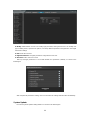
Network Settings
IP Camera Network Settings interface as shown in the follow figure:
IPV4: IP protocol version No. is 4
IPV6: IP protocol version No. is 6, the feature is not optional at present
Static IP: The device IP address is permanent
DHCP: Enable DHCP, then IP camera will get the IP address from router automatically
IP Address: Input the corresponding numbers to change the IP address
Subnet Mask: Input the corresponding IP subnet mask
Gateway: Input the corresponding gateway address
DNS 1: DNS server IP address
DNS2: DNS server second IP address
HTTP Port: Input the corresponding port ( Default is 80)
HTTPS Port: Input the corresponding port ( Default is 443)
RTSP Port: Use domain name to access and login device need mapping RTSP, default port is 554
RTMP Port: Use domain name to access and login device need mapping RTMP, default port is
1935
Enable UPnP: Enable UPnP, then device port and HTTP port will be mapped to the router
automatically
Device Port: Input the corresponding device port(Default is 5050)

13
Enable PPPoe: Click to enable PPPOE
User Name: Input the user name
Password: Input the password
Confirm pwd: Input the password again to confirm it
PPPoe IP: Input device dynamic address
After complete all parameters setting, click Save, then the settings will take effect immediately.
DDNS Setting
DDNS is implemented through a dynamic domain resolution server. It requires a PC running in the
server with fixed IP address on the Internet. IP Camera DDNS setting interface as below figure:
Enable DDNS: Click to determine whether to use Dynamic Domain Name Server
Server Type: Select DDNS server type
Server Name: Input server name
Port: Input port No.(default is 80)
Username: Input user name
Password: Input password (max 10 char.)
Confirm pwd: Input the password again to confirm it
Domain: Input the domain
After complete all parameters setting, click Save, then the settings will take effect immediately.
User Info
IP Camera User Info setting interface as below figure, admin is the administrator (default), Default
indicates general users.

14
Modify: Administrator account can modify login password, while general users can modify user
type including Guest, Operator two options, and setup different permission assignment in the Rights
Permission settings
Del: Delete the new user
Rights Permission: Set rights permission assignment for new user
Add User: Add a new user in need
Start up and login permission is accord with default user permission (default), as shown in the
follow figure:
After complete all parameters setting, click Save and then the settings will take effect immediately.
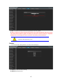
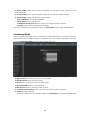
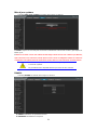
System Update
IP Camera System Update setting interface as shown in the follow figure:

15
File: Click Browse to find and select the upgrade kit, then click Update.
NOTE: to upgrade must first be uploaded the file whose name starts with (Main fw), then the one whose
name starts (Sub fw). After the upgrade is mandatory to restore the camera to the factory configuration
(default). Before reconnecting the camera, clear the IE cache memory and the old ActiveX.
Non-technician should not try to operate system upgrade, do not cut off
the power during upgrade process.
Restore
IP Camera Restore setting interface as shown in the follow figure:
Restore: Restore the factory settings
Reboot: Reboot the device

16
Exit
Click Logout to log out, as shown in the follow figure:

17
TELECAMERE SERIE IP 100
Leggere questo manuale prima dell’uso e conservarlo per consultazioni future

18
Dichiarazione
Le istruzioni qui contenute sono da considerarsi puramente indicative. Non tutti i modelli
supportano tutte le funzioni descritte.
Sebbene sia stata posta la massima cura nella preparazione del presente documento, le istruzioni
potrebbero contenere eventuali imprecisioni tecniche o errori tipografici.
Il prodotto o le procedure qui descritte possono subire modifiche o aggiornamenti in qualsiasi momento
senza preavviso.
Le schermate utilizzate nelle istruzioni sono riportate solamente a fini indicativi e illustrativi.
Per eventuali dubbi o per richiedere la documentazione relativa ai prodotti più recenti e note
complementari, consultare il servizio di assistenza post-vendita.
Precauzioni
Le seguenti precauzioni devono essere osservate rigorosamente per un corretto utilizzo del prodotto e la
prevenzione dei rischi e delle perdite materiali.
Utilizzare le telecamere in un ambiente caratterizzato da valori ammissibili di umidità e temperature.
Verificare se l'alimentatore funziona normalmente prima dell'utilizzo.
Non colpire violentemente il prodotto e fare attenzione a non farlo cadere né rovesciarlo.
Non installare il prodotto in luoghi polverosi o umidi oppure caratterizzati dalla presenza di intense
radiazioni elettromagnetiche.
Non collocare un contenitore o altri recipienti contenenti liquidi sul prodotto ed evitare che penetrino
liquidi all'interno del prodotto.
Quando il prodotto non viene utilizzato, installare il parapolvere di sicurezza per il sensore di immagine.
Non smontare il prodotto senza autorizzazione.
La page est en cours de chargement...
La page est en cours de chargement...
La page est en cours de chargement...
La page est en cours de chargement...
La page est en cours de chargement...
La page est en cours de chargement...
La page est en cours de chargement...
La page est en cours de chargement...
La page est en cours de chargement...
La page est en cours de chargement...
La page est en cours de chargement...
La page est en cours de chargement...
La page est en cours de chargement...
La page est en cours de chargement...
La page est en cours de chargement...
La page est en cours de chargement...
La page est en cours de chargement...
La page est en cours de chargement...
La page est en cours de chargement...
La page est en cours de chargement...
La page est en cours de chargement...
La page est en cours de chargement...
La page est en cours de chargement...
La page est en cours de chargement...
La page est en cours de chargement...
La page est en cours de chargement...
La page est en cours de chargement...
La page est en cours de chargement...
La page est en cours de chargement...
La page est en cours de chargement...
La page est en cours de chargement...
La page est en cours de chargement...
La page est en cours de chargement...
La page est en cours de chargement...
La page est en cours de chargement...
La page est en cours de chargement...
-
 1
1
-
 2
2
-
 3
3
-
 4
4
-
 5
5
-
 6
6
-
 7
7
-
 8
8
-
 9
9
-
 10
10
-
 11
11
-
 12
12
-
 13
13
-
 14
14
-
 15
15
-
 16
16
-
 17
17
-
 18
18
-
 19
19
-
 20
20
-
 21
21
-
 22
22
-
 23
23
-
 24
24
-
 25
25
-
 26
26
-
 27
27
-
 28
28
-
 29
29
-
 30
30
-
 31
31
-
 32
32
-
 33
33
-
 34
34
-
 35
35
-
 36
36
-
 37
37
-
 38
38
-
 39
39
-
 40
40
-
 41
41
-
 42
42
-
 43
43
-
 44
44
-
 45
45
-
 46
46
-
 47
47
-
 48
48
-
 49
49
-
 50
50
-
 51
51
-
 52
52
-
 53
53
-
 54
54
-
 55
55
-
 56
56


Comelit 100 Series Manuel utilisateur
- Taper
- Manuel utilisateur
- Ce manuel convient également à
dans d''autres langues
- italiano: Comelit 100 Series Manuale utente
- English: Comelit 100 Series User manual
Documents connexes
Autres documents
-
Eneo IPD-72A0003M0B Quick Installation Manual
-
Risco VUpoint RVCM32W Guide d'installation
-
Samsung SCC-C6475P Manuel utilisateur
-
-
-
Dahua DH-IPC-HDB4431CN Network Fixed Dome Cameras Mode d'emploi
-
AVer DL10 Mode d'emploi