
1 69-0628B—1
69-0628B-1
Heating or Cooling Thermostat and
Wallplate or Heating/Cooling
Thermostat and Subbase
T8090A/191108AJ, Q682
OWNER’S MANUAL

2 69-0628B—1
M3375
Welcome to the world of energy savings with your new Honeywell fuel saver thermostat. The
Honeywell name is your assurance of accurate control and reliable operation for years to come.
Your new thermostat will automatically lower and raise the temperature in your home one or
more times every 24 hours. This allows you to significantly lower your fuel costs, while awakening
(or returning home) to a comfortable temperature.
Read this manual to learn how to use your new thermostat.
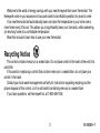
Recycling Notice
This control contains mercury in a sealed tube. Do
not
place control in the trash at the end of its
useful life.
If this control is replacing a control that contains mercury in a sealed tube, do
not
place your
control in the trash.
Contact your local waste management authority for instructions regarding recycling and the
proper disposal of this control, or of an old control containing mercury in a sealed tube.
If you have questions, call Honeywell Inc. at 1-800-468-1502.

3 69-0628B—1
Table of Contents
PAGE
Features of Your Thermostat ............................................................................................................ 4
Setting the Temperature ................................................................................................................... 7
Setting Subbase Switches ................................................................................................................ 8
Inserting Clock Batteries ................................................................................................................... 9
Setting the Clock ............................................................................................................................. 10
Programming................................................................................................................................... 11
Troubleshooting .............................................................................................................................. 14
Servicing the Thermostat ................................................................................................................ 23
Cycle rate adjustment ................................................................................................................ 23
Thermometer adjustment ........................................................................................................... 24
Warranty.......................................................................................................................................... 27

4 69-0628B—1
2
1
3
M8895
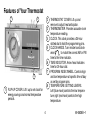
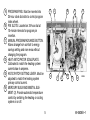
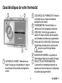
Features of Your Thermostat
1 FLIP-UP COVER. Lift it up to set clock for
energy savings and normal temperature
periods.
2 THERMOSTAT COVER. Lift up and
remove to adjust heat anticipator.
3 THERMOMETER. Provides accurate room
temperature reading.
4 CLOCK. This clock provides a 24-hour
slotted dial to hold the programming pins.
5 CLOCK HANDS. Turn minute hand clock-
wise to match the correct AM or PM
time to the time indicator.
6 TIME INDICATOR. Arrow head indicates
time for 24-hour dial.
7 PROGRAM INDEX WHEEL. Controls high
and low temperature at specific time of day
as set by program pins.
8 TEMPERATURE SETTING LEVERS.
Left (blue mark) controls the low tempera-
ture; right (red mark) controls the high
temperature.

5 69-0628B—1
5
8
9
76
11
12
13
10
14
M8896
4
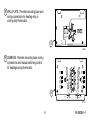
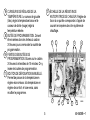
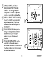
9 PROGRAM PINS. Must be inserted into
24-hour clock dial slots to control program
index wheel.
10 PIN SLOTS. Located on 24-hour dial at
10-minute intervals for program pin
insertion.
11 MANUAL PROGRAM ADVANCE BUTTON.
Allows change from comfort to energy
savings setting and vice versa without
changing the program.
12 HEAT ANTICIPATOR SCALEPLATE.
Calibrated to match the heating system
current draw in amperes.
13 ANTICIPATOR SETTING LEVER. Must be
adjusted to match the heating system
primary control current.
14 MERCURY BULB AND BIMETAL ELE-
MENT (2). Provide automatic temperature
control by switching the heating or cooling
system on or off.

6 69-0628B—1
AUTO OFF
COOL
HEATON
FAN
B
O
W
Y
R
G
M 719
16
M2421
15
15 WALLPLATE. Provides mounting base and
wiring connections for heating-only or
cooling-only thermostat.
16 SUBBASE. Provides mounting base, wiring
connections and manual switching control
for heating/cooling thermostat.

7 69-0628B—1
8
9
1
0
1
2
11
1
2
3
4
5
6
7
8
9
1
0
12
11
1
2
3
4
5
6
7
12
6
3
9
HIGH
TEMPERATURE
SETTING LEVER
(RED MARK)
LOW TEMPERATURE
SETTING LEVER
(BLUE MARK)
M1691
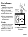
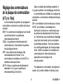
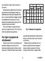
Setting the Temperature
For Heating
Set the left lever (blue mark) to the energy
savings temperature you want when you are
sleeping or your home is unoccupied.
Set the right lever (red mark) to the tempera-
ture you want for normal comfort periods.
NOTE: You may override the time program by
setting both the red and blue levers to the
same temperature setpoint.
For Cooling
Set the left lever (blue mark) to the tempera-
ture you want for normal comfort periods.
Set the right lever (red mark) to the energy
savings temperature you want when you are
sleeping or your home is unoccupied.
Fig. 1—Setting High and Low Temperature
Setting Levers.

8 69-0628B—1
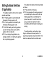
Setting Subbase Switches
(If applicable)
The subbase system switch controls system
operation as follows:
HEAT—Heating system is controlled by the
thermostat. Cooling system is off.
COOL—Cooling system is controlled by the
thermostat. Heating system is off.
OFF—Both the heating and cooling systems
are off. If the fan switch is at the AUTO
position, the fan is also off.
AUTO—In a cooling only application, only
cooling operates. In a heating only applica-
tion, only heating operates.
The subbase fan switch controls fan operation
as follows:
ON—Fan operates continuously.
AUTO—Fan operates with cooling equipment
as controlled by the thermostat or with the
heating equipment as controlled by the
plenum fan switch. In electric heat, heat
pump, and fan coil systems, the fan is
controlled by the thermostat in heating and
cooling.
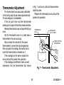
To switch positions, use thumb or index
finger to slide lever to desired position. For
proper circuit operation, stop switch lever in the
detent over desired function indicator mark.

9 69-0628B—1
BATTERY LOCATION FOR
(2) AAA BATTERIES;
INSTALL WITH POSITIVE
ENDS UP
M7188
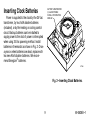
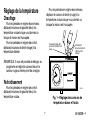
Inserting Clock Batteries
Power is supplied to the clock by the 24 Vac
transformer, by two AAA alkaline batteries
(included), or by the heating or cooling control
circuit. Backup batteries can be installed to
supply power to the clock if power is interrupted
when using 24 Vac powering method. Install
batteries in thermostat as shown in Fig. 2. Once
a year or when batteries are dead, replace with
two new AAA alkaline batteries. We recom-
mend Energizer
®
batteries.
Fig. 2—Inserting Clock Batteries.

10 69-0628B—1
TIME
INDICATOR
ARROW
MINUTE
HAND
M8561
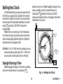
Setting the Clock
Lift thermostat flip-up cover and you will find
the 24-hour program dial, slotted in ten minute
increments. Adjust the clock to the current time
by moving the minute hand carefully in a clock-
wise direction. DO NOT reverse the
minute hand.
When time is correctly set, the Time Indica-
tor Arrow (see Fig. 3) points to the correct time
and corresponding daytime (light) or nighttime
(dark) band of the program dial.
EXAMPLE: For 11 PM, the time indicator arrow
points directly to dark band. For 11 AM, the
arrow points to the light band on the dial.
Daylight Savings Time
When Daylight Savings Time starts, carefully
move the minute hand in a clockwise
direction one hour. When Daylight Savings Time
ends, carefully move the minute hand in a
clockwise direction 23 hours. Do NOT
reverse the minute hand, or damage to the timer
mechanism can occur.
Fig. 3—Setting the Clock.

11 69-0628B—1
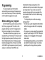
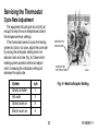
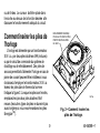
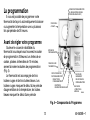
Programming
You can program your thermostat to
automatically lower and raise the temperature
one or more times every 24 hours, depending
on the number of program pins used.
Before setting your program
Lift thermostat flip-up cover and you will find
the 24-hour program dial. The slots on the
program dial (Fig. 4) are for the program pins
that can be inserted at ten minute intervals.
Three red and three blue program pins are
included with your thermostat. The red pins start
the high-temperature period; the blue pins start
the low-temperature period. A heating program
has been preprogrammed. A red pin is inserted
at 6:00 AM for high temperature (comfort period);
a blue pin is inserted at 10:00 PM for low
temperature (energy saving period). Two
additional sets of pins are located in the program
pin storage area. You can set up to six tem-
perature changes with the pins supplied. We
recommend at least five hours for each energy
saving period.
To change the pins or add a new energy
savings period—
• To insert a pin, push it straight into the selected
notch on the program dial until it is completely
seated.
• To remove a pin, press against the program dial
and pull the pin straight out. DO NOT attempt to
change a pin if it is engaged with the program
index wheel.
• On heating/cooling systems, you must reset the
pins when the seasons change. You will also
probably want to change the lever positions.

12 69-0628B—1
24-HOUR PROGRAM DIAL
(GRAY AREA FOR
NIGHT SETTINGS)
FLIP-UP
COVER
PROGRAM
PINS
THERMOSTAT
COVER
PROGRAM PIN SLOT
PROGRAM INDEX WHEEL
PROGRAM PIN
STORAGE
TIME INDICATOR
ARROW
MANUAL PROGRAM
ADVANCE BUTTON
M8692
Fig. 4—Program Components.
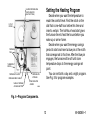
Setting the Heating Program
Decide when you want the temperature to
reach the comfort level. Find the notch on the
dial that is one-half hour before this time and
insert a
red
pin. The half-hour head start gives
the furnace time to heat the house before you
wake up or arrive home.
Decide when you want the energy savings
period to start and insert a
blue
pin at the notch
that corresponds to this time. After the blue pin
engages, the furnace will be off until room
temperature drops to the energy savings set
point.
You can set both a day and a night program.
See Fig. 5 for program examples.

13 69-0628B—1
WINTER SUMMER
TEMPERATURE
PROGRAM
PIN IN
CONTROL
NIGHT
ENERGY
SAVING
PERIOD
DAY
ENERGY
SAVING
PERIOD
BEGINS
10:00 PM
ENDS
6:00 AM
BEGINS
7:30 AM
ENDS
4:00 PM
TEMPERATURE
PROGRAM
PIN IN
CONTROL
°C
27
24
27
24
RED
BLUE
RED
BLUE
°F
58
68
58
68
°C
14
20
14
20
°F
80
75
80
75
BLUE
RED
BLUE
RED
M1690B
Fig. 5—Program Examples.
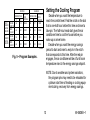
Setting the Cooling Program
Decide when you want the temperature to
reach the comfort level. Find the notch on the dial
that is one-half hour before this time and insert a
blue
pin. The half-hour head start gives the air
conditioner time to cool the house before you
wake up or arrive home.
Decide when you want the energy savings
period to start and insert a
red
pin in the notch
that corresponds to this time. After the red pin
engages, the air conditioner will be off until room
temperature rises to the energy savings setpoint.
NOTE: Due to weather and system variations,
the program pins may need to be relocated for
optimum start time of heating or cooling equip-
ment during recovery from energy savings.

14 69-0628B—1
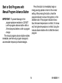
Start or End Programs with
Manual Program Advance Button
IMPORTANT:
To prevent damage to the
program advance mechanism. DO NOT
use the program advance button within a
30-minute period before or after a program
change.
The manual program advance button enables
immediate, one-time-only program changes to
accommodate temporary schedule changes.
Press the button to immediately begin an
energy savings period or return to the normal
setting. After pressing the button, check the
program indicator to ensure the system is in the
desired mode. If the program indicator shows
blue, the lower temperature is in effect; if it shows
red, the higher temperature is in effect. Using the
manual advance button will not affect the stored
program.

15 69-0628B—1
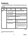
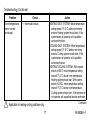
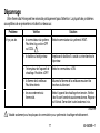
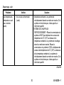
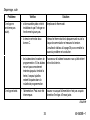
Problem Check Action
No heat. — system switch. May be in OFF
or COOL position. 1
Move system switch to HEAT position.
— fuse or circuit breaker. If blown or tripped, replace fuse or reset breaker.
— furnace power switch. May be
Off.
Move switch to ON .
— pilot flame. May be out. Relight pilot flame per furnace manufacturer’s
instructions.
— thermostat connections. Turn Off power to furnace. Check for correct
terminal hookups. Repair any frayed or broken
wires. Firmly tighten all terminal screws. Turn
power On.
1 Applicable to heating-cooling subbase only.
Continued
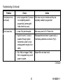
Troubleshooting
Your Honeywell thermostat requires little or no attention. Most problems can generally be traced
to the following:

16 69-0628B—1
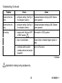
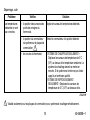
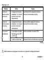
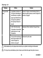
Troubleshooting (Continued)
Problem Check Action
No heat (continued). — other. Contact a qualified service technician for
assistance.
Energy savings
temperature program
12 hours off.
— program dial for proper day or
night phase.
Turn clock ahead 12 hours. Move minute hand
clockwise only.
Rooms do not warm
up at programmed
time.
— timer program for heating
system. May need more time
to warm up rooms.
Move red pin one-half hour earlier on the
program dial.
Temperature change
occurs at the wrong
time.
— program pins for correct time
locations.
Relocate pins to desired settings.
Room temperatures
are not correct.
— positions of thermostat set
point levers.
Reset to desired temperatures.
— position of subbase system
switch. 1
Move to desired operating position.
Continued

17 69-0628B—1
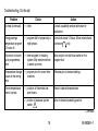
Troubleshooting (Continued)
Continued
Problem Check Action
Room temperatures
are not correct
(continued).
— thermostat circuits. HEATING-ONLY SYSTEM—Move temperature
setting levers 5°F (3°C) above room temp-
erature. Heating system should start. If the
system does not operate, call a qualified
service technician.
COOLING-ONLY SYSTEM—Move temperature
setting levers 5°F (3°C) below room temp-
erature. Cooling system should start. If the
system does not operate, call a qualified
service technician.
HEATING/COOLING SYSTEM—With system
switch at HEAT, move temperature setting
levers 5°F (3°C) above room temperature.
Heating system should start. With system
switch at COOL, move temperature setting
levers 5°F (3°C) below room temperature.
Cooling system should start. If the systems do
not operate, call a qualified service technician.
1 Applicable to heating-cooling subbase only.

18 69-0628B—1
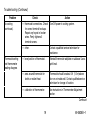
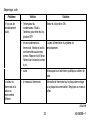
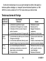
Troubleshooting (Continued)
1 Applicable to heating-cooling subbase only.
Problem Check Action
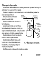
Burner-on time too
short.
— anticipator setting. (See Fig. 6
for anticipator location.)
Increase anticipator setting by 0.05. Observe
burner operation.
Burner-on time too
long.
— anticipator setting. (See Fig. 6
for anticipator location.)
Decrease anticipator setting by 0.05. Observe
burner operation.
No cooling. — system switch. May be in OFF
or HEAT position. 1
Move switch to COOL position.
— fuse or circuit breaker. If fuse is blown or breaker tripped, replace or
reset.
— condenser switch position.
Located outdoors and may be
turned Off.
Move to ON position.
Continued

19 69-0628B—1
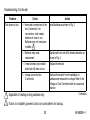
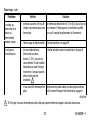
Troubleshooting (Continued)
Continued
Problem Check Action
No cooling
(continued).
— thermostat connections. Check
for correct terminal hookups.
Repair any frayed or broken
wires. Firmly tighten all
terminal screws.
Turn Off power to cooling system.
— other. Contact a qualified service technician for
assistance.
Thermostat setting
and thermometer
reading disagree.
— level position of thermostat. Reinstall thermostat wallplate or subbase. Use a
spirit level.
— area around thermostat for
drafts or radiant heat.
Thermostat should be about 5 ft (1.5 m)above
floor on an inside wall. Contact qualified service
technician for change of location.
— calibration of thermometer. See instructions in Thermometer Adjustment
section.

20 69-0628B—1
Problem Check Action
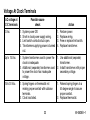
Clock does not run. — thermostat connections at the
two C terminals. If no
connections, clock needs
batteries in order to run.
Batteries may not have been
installed. 2
Install batteries as shown in Fig. 2.
— Batteries may need
replacement.
Replace with two new AAA alkaline batteries as
shown in Fig. 2.
— if new batteries are installed
and clock still does not run.
Replace thermostat.
— voltage across the two
C terminals.
Remove thermostat from the wallplate or
subbase and measure the voltage. Refer to the
Voltage at Clock Terminals table for cause and
reaction.
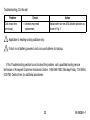
Troubleshooting (Continued)
1 Applicable to heating-cooling subbase only.
2 If clock is not battery powered, clock can use batteries for backup.
Continued
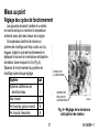
La page est en cours de chargement...
La page est en cours de chargement...
La page est en cours de chargement...
La page est en cours de chargement...
La page est en cours de chargement...
La page est en cours de chargement...
La page est en cours de chargement...
La page est en cours de chargement...
La page est en cours de chargement...
La page est en cours de chargement...
La page est en cours de chargement...
La page est en cours de chargement...
La page est en cours de chargement...
La page est en cours de chargement...
La page est en cours de chargement...
La page est en cours de chargement...
La page est en cours de chargement...
La page est en cours de chargement...
La page est en cours de chargement...
La page est en cours de chargement...
La page est en cours de chargement...
La page est en cours de chargement...
La page est en cours de chargement...
La page est en cours de chargement...
La page est en cours de chargement...
La page est en cours de chargement...
La page est en cours de chargement...
La page est en cours de chargement...
La page est en cours de chargement...
La page est en cours de chargement...
La page est en cours de chargement...
La page est en cours de chargement...
La page est en cours de chargement...
La page est en cours de chargement...
La page est en cours de chargement...
La page est en cours de chargement...
La page est en cours de chargement...
La page est en cours de chargement...
La page est en cours de chargement...
La page est en cours de chargement...
-
 1
1
-
 2
2
-
 3
3
-
 4
4
-
 5
5
-
 6
6
-
 7
7
-
 8
8
-
 9
9
-
 10
10
-
 11
11
-
 12
12
-
 13
13
-
 14
14
-
 15
15
-
 16
16
-
 17
17
-
 18
18
-
 19
19
-
 20
20
-
 21
21
-
 22
22
-
 23
23
-
 24
24
-
 25
25
-
 26
26
-
 27
27
-
 28
28
-
 29
29
-
 30
30
-
 31
31
-
 32
32
-
 33
33
-
 34
34
-
 35
35
-
 36
36
-
 37
37
-
 38
38
-
 39
39
-
 40
40
-
 41
41
-
 42
42
-
 43
43
-
 44
44
-
 45
45
-
 46
46
-
 47
47
-
 48
48
-
 49
49
-
 50
50
-
 51
51
-
 52
52
-
 53
53
-
 54
54
-
 55
55
-
 56
56
-
 57
57
-
 58
58
-
 59
59
-
 60
60


Honeywell 19908AJ Le manuel du propriétaire
- Catégorie
- Thermostats
- Taper
- Le manuel du propriétaire
dans d''autres langues
- English: Honeywell 19908AJ Owner's manual
Documents connexes
-
Honeywell T8132 Le manuel du propriétaire
-
-
-
-
Honeywell TH8000 Manuel utilisateur
-
Honeywell RTH8500 Le manuel du propriétaire
-
Honeywell RTH7600 Le manuel du propriétaire
-
-
Honeywell T8775A,C Manuel utilisateur