Sachtler ACE Manuel utilisateur
- Catégorie
- Accessoires pour appareil photo
- Taper
- Manuel utilisateur

Ace Base Plate
Manual

Copyright © 2013
All rights reserved.
Publication number: S2154-4980/2
Original instructions: English.
All rights reserved throughout the world. No part of this
document may be stored in a retrieval system, transmitted,
copied or reproduced in any way, including, but not limited
to, photocopy, photograph, magnetic or other record
without the prior agreement and permission in writing of
the Vitec Group plc.
We want you to receive Sachtler products that are always
state of the art. Therefore we reserve the right to make
changes based on technical advances.
Disclaimer
The information contained in this manual is believed to be
correct at the time of printing. Vitec Videocom Ltd reserves
the right to make changes to the information or
specifications without obligation to notify any person of
such revision or changes. Changes will be incorporated in
new versions of the publication.
We are making every effort to ensure that our manuals are
updated on a regular basis to reflect changes to product
specifications and features. Should this manual not contain
information on the core functionality of your product,
please let us know. You may be able to access the latest
revision of this manual from our website.
Vitec Videocom Ltd reserves the right to make changes to
product design and functionality without notification.
Published by:
Vitec Videocom Ltd
Supports Technical Publications Department
William Vinten Building
Western Way
Bury St Edmunds
Suffolk IP33 3TB
United Kingdom
E-mail: [email protected]

Ace Base Plate
Manual
English . . . . . . . . . . . . . . . . . . . . . Page 1
Deutsch. . . . . . . . . . . . . . . . . . . . Seite 11
Español . . . . . . . . . . . . . . . . . . .Página 21
Français . . . . . . . . . . . . . . . . . . . Page 31
Português . . . . . . . . . . . . . . . . .Página 41
中文 . . . . . . . . . . . . . . . . . . . . . . . 页码 51


-1-
EN
EN
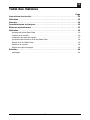
Table of contents
Page
Safety instructions . . . . . . . . . . . . . . . . . . . . . . . . . . . . . . . . . . . . . . . . . . . . . . . . . 2
Usage. . . . . . . . . . . . . . . . . . . . . . . . . . . . . . . . . . . . . . . . . . . . . . . . . . . . . . . . . . . . 2
Warranty . . . . . . . . . . . . . . . . . . . . . . . . . . . . . . . . . . . . . . . . . . . . . . . . . . . . . . . . . 2
Technical specification . . . . . . . . . . . . . . . . . . . . . . . . . . . . . . . . . . . . . . . . . . . . . 2
Operating elements . . . . . . . . . . . . . . . . . . . . . . . . . . . . . . . . . . . . . . . . . . . . . . . . 3
Operation . . . . . . . . . . . . . . . . . . . . . . . . . . . . . . . . . . . . . . . . . . . . . . . . . . . . . . . . 5
Mounting the Ace Base Plate. . . . . . . . . . . . . . . . . . . . . . . . . . . . . . . . . . . . . . . . . . . . . . . 5
Mounting the camera . . . . . . . . . . . . . . . . . . . . . . . . . . . . . . . . . . . . . . . . . . . . . . . . . . . . . 6
Installing support rods . . . . . . . . . . . . . . . . . . . . . . . . . . . . . . . . . . . . . . . . . . . . . . . . . . . . 7
Ace Base Plate height adjustment . . . . . . . . . . . . . . . . . . . . . . . . . . . . . . . . . . . . . . . . . . . 8
Removing the Ace Base Plate . . . . . . . . . . . . . . . . . . . . . . . . . . . . . . . . . . . . . . . . . . . . . . 9
Removing the camera.. . . . . . . . . . . . . . . . . . . . . . . . . . . . . . . . . . . . . . . . . . . . . . . . . . . . 9
Removing support rods . . . . . . . . . . . . . . . . . . . . . . . . . . . . . . . . . . . . . . . . . . . . . . . . . . 10
Maintenance . . . . . . . . . . . . . . . . . . . . . . . . . . . . . . . . . . . . . . . . . . . . . . . . . . . . . 10
Cleaning. . . . . . . . . . . . . . . . . . . . . . . . . . . . . . . . . . . . . . . . . . . . . . . . . . . . . . . . . . . . . . 10

-2-
EN
EN
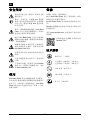
Safety instructions
Read the General Safety and
Operating instructions before using
th
e product.
WARNING! Finger entrapment. Do not
place fingers between the upper and
lower
platform when adjusting the
height of the Ace Base Plate. Avoid
tr
apping fingers when adjusting the
height of the Ace Base Plate.
WARNING! Ensure that the camera
slide plate engages with the retention
latch on the Ace Base Plat
e platform.
Failure to do so could cause personal
injury or damage to equipment.
Hold the camera securely when
(a) mounting or dismounting from the
Ace Base Plate
(b) when making
adjustments to the tripod height or
footprint.
Ensure that the support rods are
installed through both the front and
r
ear support rod housings. Failure to
do so could cause damage to the Ace
Base Plate.
Clean regularly using a soft cloth and
mild detergent.
Dry the product after use in wet
conditions.
Should the product become defective,
contact your local Sachtler service
centr
e. To find your local service
centre visit www.sachtler.com
Usage
The Ace Base Plate is designed for use by
professional camera operators to support and
balance high-performance lightweight
cameras and ancillary equipment weighing up
to 6 kg (13.2 lb). The Ace Base Plate must be
mounted onto a suitable head and tripod
designed to support the total payload.
Warranty
The warranty expires if:
(a) The Ace Base Plate was operated
impr
operly or not in line with the specified
technical data.
(b) The Ace Base Plate housing was opened
b
y unauthorized personnel.
Sachtler reserve the right to make changes to
p
roduct design and performance as
technology advances.
Please register your product for an extended
w
arranty period at www.sachtler.com
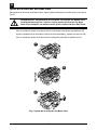
Scan Quick Reference (QR)
code to visit the Sachtler
website.
Technical specification
0.55 kg (1.2 lb)
Fully retracted - 4.8 cm (1.9 in.)
Fully extended - 7.2 cm (2.8 in.)
11.4 cm (4.5 in.)
13.3 cm (5.2 in.)
6 kg (13.2 lb)

-3-
EN
EN
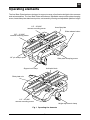
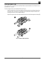
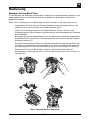
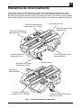
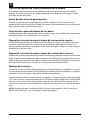
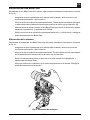
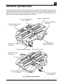
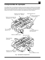
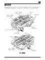
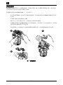
Operating elements
The Ace Base Plate has been designed to support a range of professional digital video cameras
and rod assemblies. The Ace Base Plate embodies an adjustable camera slide plate clamping
screw, head slide plate attachment points, rod assembly housing and adjustable platform height.
Ace slide plate
Slide release button
Slide plate clamping screw
Support rod clamp
Height adjustment clamp
Slide plate rule
1/4” - 20 UNC
camera mounting screw
3/8” - 16 UNC
camera mounting screw
Anti-twist block
1/4” pin and pin plate
1/4” - 20 UNC
camera mounting screw
Fig. 1 Operating the elements

-4-
EN
EN
Camera slide plate clamping screw
The Ace Base Plate allows the camera slide plate to be locked at any chosen position. The
camera slide plate clamping screw is located on the left-hand side of the Ace Base Plate.
Slide release button
The red slide release button, when pressed, allows the Ace slide plate to be removed from the
Ace Base Plate. The slide release button is located on the aft left-hand side of the Ace Base
Plate.
Head slide plate attachment
The head slide plate is secured to the underside of the Ace Base Plate using either 1/4 in. or
3/8 in. camera fixing screws.
Support rod adjustment clamp
The Ace Base Plate allows support rods (x2) to be fitted and adjusted as required. The support
rods are fitted into the support rod housing and secured by the support rod clamp, located on
the forward left-hand side of the Ace Base Plate.
Camera height adjustment clamp
The camera height can be adjusted by raising or lowering the upper platform of the Ace Base
Plate. When the camera is at the required height, the Ace Base Plate can be secured in place
by the camera height clamp. The camera height clamp is mounted on the right-hand side of the
Ace Base Plate.
Camera mounting
The camera is attached to the Ace Base Plate using an Ace slide plate, that is attached to the
camera and then loaded from the rear of the platform and secured in position by the camera slide
plate clamping screw.
The Ace slide plate is supplied with 1/4 in. camera fixing screw and pin and a DSLR anti-twist
block. The anti-twist block prevents the DSLR camera from twisting side to side, when fitted.
Additionally, two spare camera screws are located in the screw stowage position on the
underside of the Ace slide plate
NOTE: Some cameras, including DSLRs, do not require the pin. Remove the 1/4” camera fixing
screw to release the pin plate.

-5-
EN
EN
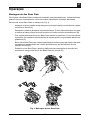
Operation
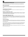
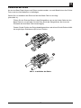
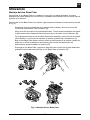
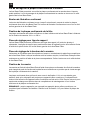
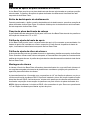
Mounting the Ace Base Plate
To mount the Ace Base Plate onto the head, a slide plate is required. The slide plate can be fitted
with the screws and pin supplied, depending on the camera attachment.
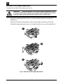
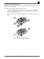
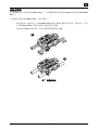
To mount the Ace Base Plate onto the head (see Fig. 2):
Ensure that the head platform is level and app
ly both the pan and tilt brakes [A].
Loosen the slide plate clamping screw. Pull the Ace slide plate to the rear of the fluid
head whilst pressing the red release button [B].
Attach the Ace slide plate to the Ace Base
Plate using the camera screws and pin
supplied. Spare camera screws can be stored under the platform [C].
Lower the Ace Base Plate onto the rear of the head and slide the plate into the track in
the platfor
m, ensuring the slide lock release button snaps into position [D].
Steady the Ace Base Plate and tighten the slide plate clamp
in a clockwise direction to
secure the Ace Base Plate in position [D].
A
B
C
D
Fig. 2 Mounting the Ace Base Plate

-6-
EN
EN
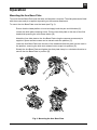
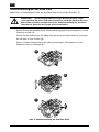
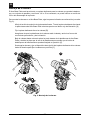
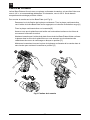
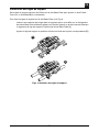
Mounting the camera
The Ace Base Plate is supplied with a camera slide plate, that can be fitted with a 1/4 in. screw
and pin assembly. If required, a 3/8 in. screw, located in the spare stowage can be used.
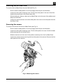
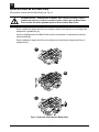
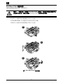
To mount the camera onto the Ace Base Plate (see Fig. 3):
Loosen the slide plate clamping screw. Pull the Ace slide plate to the r
ear of the Ace
Base Plate whilst pressing the red release button [A].
Attach the Ace slide plate to the camera [B].
Ensure that the head platform is level and apply both the pan and tilt brakes.
Lower the camera onto the rear of the Ace Base Plate platform and slide the plate into
the tr
ack in the platform, ensuring the slide lock release button snaps into position [C].
Steady the camera and rotate the camera slide plate cla
mp in a clockwise direction to
secure the camera in position [C].
A
B
C
Fig. 3 Mounting the camera

-7-
EN
EN
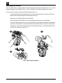
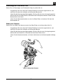
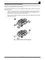
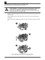
Installing support rods
Two support rods can be fitted to the Ace Base Plate to accommodate an Ace Follow Focus or
Ace Matte Box if required.
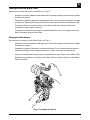
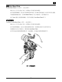
To fit the support rods to the Ace Base Plate (see Fig. 4):
Insert one end of the rod into the support rod housing at the front left-hand side of the
Ace
Base Plate, and continue to slide back until it protrudes through the support rod
housing at the rear of the Ace Base Plate [A].
Adjust the support rod to the required position
and secure with the support rod clamp [B].
A
B
Fig. 4 Support Rod Installation

-8-
EN
EN
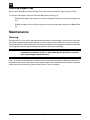
Ace Base Plate height adjustment
To adjust the Ace Base Plate height (see Fig. 5):
WARNING! Finger entrapment. Do not place fingers between the upper
and lower platform when adjusting the height of the Ace Base Plate. Avoid
trapp
ing fingers when adjusting the height of the Ace Base Plate.
Rotate the height adjustment knob in a coun
ter-clockwise direction to loosen the
platform [A].
Adjust the Ace Base Plate platform to th
e required height and hold in position [B].
Rotate the height adjustment knob in a clockwise direction to secure the platform [C].
A
B
C
Fig. 5 Ace Base Plate height adjustment

-9-
EN
EN
Removing the Ace Base Plate
To remove the Ace Base Plate from the head (see Fig. 2):
Ensure that the head platform is level and apply both the pan and tilt brakes.
Loosen the slide plate clamping screw. Pull the Ace slide plate to the r
ear of the fluid
head whilst pressing the red release button [B].
Whilst holding the camera, slide the Ace Base Plate out to the rear of the platform and
away fro
m the head.
Loosen the camera screws on the Ace slide plate, then remove the slide plate from the
Ac
e Base Plate.
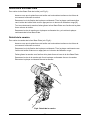
Removing the camera.
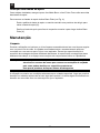
To remove the camera from the Ace Base Plate (see Fig. 6):
Ensure that the head platform is level and apply both the pan and tilt brakes.
Loosen the slide plate clamping screw. Pull the slide plate to the
rear of the fluid head
whilst pressing the red release button.
Slide the camera out to the rear of the platform and away from the Ace Base Plate.
Loosen the camera screws securing the Ace slide plate to t
he camera. Remove the Ace
slide plate from the camera.
Fig. 6 Removing the camera

-10-
EN
EN
Removing support rods
Ensure Ace Matte Box and Ace Follow Focus are removed from the support rods, if fitted.
To remove the support rods from the Ace Base Plate (see Fig. 4):
Rotate the support rod clamp in a counter-clockw
ise direction to loosen the support rod
[A].
Slide the support rod out of the support rod hou
sing and away from the Ace Base Plate
[A].
Maintenance
Cleaning
During indoor use, the only cleaning required should be a regular wipe over with a lint-free cloth.
Dirt accumulated during storage may be removed using a semi-stiff brush or vacuum cleaner.
Particular attention should be paid to the camera slide plate mounting face, the head slide plate
mounting face and the space between the platform and lower assembly.
CAUTION! Do NOT use solvent or oil-based cleaners, abrasives or wire brushes to
r
emove accumulations of dirt, as these damage the protective surfaces.
Use only detergent-based cleaners.
Use out-of-doors under adverse conditions will require
special attention. Salt spray should be
washed off with fresh clean water at the earliest opportunity. Sand and dirt acts as an abrasive
and should be removed using a semi-stiff brush or vacuum cleaner.

-11-
EN
DE
Inhalt
Seite
Sicherheitshinweise. . . . . . . . . . . . . . . . . . . . . . . . . . . . . . . . . . . . . . . . . . . . . . . 12
Nutzung . . . . . . . . . . . . . . . . . . . . . . . . . . . . . . . . . . . . . . . . . . . . . . . . . . . . . . . . . 12
Gewährleistung . . . . . . . . . . . . . . . . . . . . . . . . . . . . . . . . . . . . . . . . . . . . . . . . . . 12
Technische Daten. . . . . . . . . . . . . . . . . . . . . . . . . . . . . . . . . . . . . . . . . . . . . . . . . 12
Bedienelemente . . . . . . . . . . . . . . . . . . . . . . . . . . . . . . . . . . . . . . . . . . . . . . . . . . 13
Bedienung. . . . . . . . . . . . . . . . . . . . . . . . . . . . . . . . . . . . . . . . . . . . . . . . . . . . . . . 15
Montage der Ace Base Plate . . . . . . . . . . . . . . . . . . . . . . . . . . . . . . . . . . . . . . . . . . . . . . 15
Montage der Kamera . . . . . . . . . . . . . . . . . . . . . . . . . . . . . . . . . . . . . . . . . . . . . . . . . . . . 16
Installation der Rohre. . . . . . . . . . . . . . . . . . . . . . . . . . . . . . . . . . . . . . . . . . . . . . . . . . . . 17
Höheneinstellung der Ace Base Plate . . . . . . . . . . . . . . . . . . . . . . . . . . . . . . . . . . . . . . . 18
Demontage der Ace Base Plate. . . . . . . . . . . . . . . . . . . . . . . . . . . . . . . . . . . . . . . . . . . . 19
Abbau der Kamera. . . . . . . . . . . . . . . . . . . . . . . . . . . . . . . . . . . . . . . . . . . . . . . . . . . . . . 19
Abnahme der Rohre. . . . . . . . . . . . . . . . . . . . . . . . . . . . . . . . . . . . . . . . . . . . . . . . . . . . . 20
Wartung. . . . . . . . . . . . . . . . . . . . . . . . . . . . . . . . . . . . . . . . . . . . . . . . . . . . . . . . . 20
Reinigung. . . . . . . . . . . . . . . . . . . . . . . . . . . . . . . . . . . . . . . . . . . . . . . . . . . . . . . . . . . . . 20

-12-
EN
DE
Sicherheitshinweise
Lesen Sie sich vor Verwendung des
Produkts bitte die allgemeinen
Sicherheits- und Betr
iebshinweise
durch.
WARNUNG! Quetschungsgefahr für
Finger! Bringen Sie Ihre Finger nicht
zwischen d
ie obere und untere
Plattform, wenn Sie die Höhe der Ace
Base Plate einstellen. Achten Sie bei
d
er Höheneinstellung der Ace Base
Plate darauf, dass Sie Ihre Finger
nicht einklemmen!
WARNUNG! Stellen Sie sicher, dass
die Kamera-Verschiebeplatte mit der
R
ückhaltefeder auf der Kameraplatte
der Ace Base Plate sicher einrastet.
Die Nichtbeachtung dieser Anweisung
kann Körperverletzung oder eine
Beschädigung der Ausrüstung zur Fol-
ge haben.
Halten Sie die Kamera fest in der
Hand, wenn Sie sie (a) auf die Ace
Base Pla
te aufsetzen bzw. abnehmen
und (b) Höhe oder Auszug des Stativs
einstellen.
Vergewissern Sie sich, dass die Rohre
ordnungsgemäß montiert und sowohl
d
urch das vordere als auch durch das
hintere Rohrgehäuse geführt wurden.
Die Nichtbeachtung dieser Anweisung
kann eine Beschädigung der Ace
Base Plate zur Folge haben.
Reinigen Sie das System regelmäßig
mit einem weichen Tuch und sanften
R
einigungsmittel.
Trocknen Sie das Produkt nach einer
Verwendung bei feuchten und nassen
Bed
ingungen.
Wenden Sie sich bei Schäden am
Produkt an Ihren Sachtler Service
C
enter. Die Adresse finden
www.sachtler.com
Nutzung
Die Ace Base Plate wurde für den professio-
nellen Einsatz mit DSLR und HDV Kameras
b
is zu einem Gewicht von 6 kg entwickelt. Die
Ace Base Plate muß auf einem geeignete
Stativsystem montiert werden, dessen
Traglast für den Aufbau geeignet ist.
Gewährleistung
In folgenden Fällen verliert die
Gewährleistung ihre Gültigkeit:
(a) Die Ace Base Plate wurde unsachgemäß
u
nter Missachtung der angegebenen
technischen Daten eingesetzt.
(b) Das Gehäuse der Ace Base Plate wurde
von unq
ualifiziertem Personal geöffnet.
Sachtler behält sich das Recht vor, parallel
zum technologischen F
ortschritt Änderungen
an Produktdesign und -leistung vorzunehmen.
Unter www.sachtler.com können Sie Ihr Pro-
dukt für die erweiterte Gewährleistung
registrieren.
Scannen Sie den QR-Code, um
direkt zur Sachtler-Website zu
gelan
gen.
Technische Daten
0,55 kg
Voll eingefahren – 4,8 cm
Voll ausgefahren – 7,2 cm
11,4 cm
13,3 cm
6 kg

-13-
EN
DE
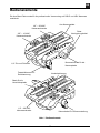
Bedienelemente
Die Ace Base Plate wurde für die professionelle Verwendung mit DSLR und HDV Kameras
entwickelt.
Ace-Kameraplatte
Verdrehsicherung
1/4”-Pin und Pinhalter
1/4” – 20 UNC
Kameraschraube
3/8” – 16 UNC
Kameraschraube
1/4” – 20 UNC
Kameraschraube
Klemmschraube für die
Kameraplatte
Roter
Verriegelungshebel
Feststellklammer für
Rohrklemmung
Skala für die
Verschiebeplatte
Klemmhebel für Höhenverstellung
Abb. 1 Bedienelemente

-14-
EN
DE
Klemmschraube für die Kameraplatte
Die Kameraplatte kann bedarfsgerecht in jeder beliebigen Position auf der Ace Base Plate
gesichert werden. Die Klemmschraube zur Befestigung der Kameraplatte befindet sich auf der
linken Seite der Ace Base Plate.
Verriegelungshebel
Durch Drücken des roten Verriegelungshebel kann die Ace Kameraplatte von der Ace Base
Plate abgenommen werden. Der Verriegelungshebel befindet sich auf der linken Seite der Ace
Base Plate.
Befestigungselemente für die Kameraplatte
Die Kameraplatte wird an der Unterseite der Ace Base Plate mithilfe von 1/4-Zoll-
oder 3/8-Zoll-Kameraschrauben angebracht.
Rohrklemmung
An der Ace Base Plate können Rohre (x2) befestigt und bedarfsgerecht positioniert werden. Die
Rohre werden in das Rohrgehäuse eingeführt und mithilfe der Rohrklemmung vorn an der linken
Seite der Ace Base Plate befestigt.
Klemmhebel für die Höhenverstellung
Die Kamerahöhe kann durch Anheben bzw. Absenken der oberen Plattform der Ace Base Plate
angepasst werden. Sobald sich die Kamera auf der richtigen Höhe befindet, lässt sich die Ace
Base Plate mithilfe des Klemmhebels für die Höhenverstellung sicher in ihrer Position
verankern. Der Klemmhebel für die Höhenverstellung befindet sich an der rechten Seite der Ace
Base Plate.
Kameramontage
Die Kamera wird mit der Ace Base Plate über die Ace Kameraplatte verbunden, die an der
Kamera angebracht, von der Rückseite der Plattform her eingesetzt und mithilfe der
Klemmschraube für die Kameraplatte sicher befestigt wird.
Die Ace Kameraplatte wird mit einer 1/4-Zoll-Kameraschraube, einem Pin und einer DSLR-
Verdrehsicherung geliefert. Die Verdrehsicherung verhindert eine seitliche Verdrehung der
Spiegelreflexkamera. Darüber hinaus sind zwei Ersatzkameraschrauben in der Parkposition an
der Unterseite der Ace Base Plate Platform verfügbar.
HINWEIS: Für einige Kameras, einschließlich der DSLR-Modelle, ist der Pin nicht erforderlich.
Entfernen Sie die 1/4-Zoll-Kameraschraube, um den Pinhalter zu lösen.

-15-
EN
DE
Bedienung
Montage der Ace Base Plate
Für die Montage der Ace Base Plate auf dem Fluidkopf ist eine Kameraplatte erforderlich. Die
Kameraplatte kann je nach Kamera mithilfe der mitgelieferten Schrauben und des Pins
angebracht werden.
Gehen Sie zur Montage der Ace Base Plate auf dem Fluidkopf vor wie folgt (siehe Abb. 2):
Vergewissern Sie sich, dass die Fluidkopf-Plattform ho
rizontal ausgerichtet ist, und
ziehen Sie dann die horizontale und vertikale Bremsen [A] an.
Lösen Sie die Klemmschraube der Fluidkopf-
Plattform. Drücken Sie den roten
Entriegelungsknopf [B] und ziehen Sie gleichzeitig die Ace Kameraplatte zur Rückseite
des Fluidkopfes.
Befestigen Sie die Ace Kameraplatte an der Ace Base
Plate mithilfe der mitgelieferten
Kameraschrauben und des Pins. Ersatzkameraschrauben können unter der Plattform
aufbewahrt werden [C].
Senken Sie die Ace Base Plate auf die Rückseit
e des Stativkopfes ab und führen Sie
die Platte in die Gleitschiene auf der Plattform ein. Stellen Sie dabei sicher, dass der
Verriegelungshebel für den Gleitmechanismus sicher in seiner Position einrastet [D].
Stabilisieren Sie die Ace Base Plate und drehen Sie die Klemmschraube der
Kamerap
latte im Uhrzeigersinn fest, um die Ace Base Plate sicher in ihrer Position zu
verankern [D].
A
B
C
D
Abb. 2 Montage der Ace Base Plate

-16-
EN
DE
Montage der Kamera
Die Ace Base Plate wird mit einer Kameraplatte geliefert, die mithilfe einer
Befestigungsbaugruppe aus 1/4-Zoll-Schraube und Pin angebracht werden kann. Falls
erforderlich, kann die 3/8-Zoll-Schraube aus der Parkposition verwendet werden.
Gehen Sie zur Montage der Kamera auf der Ace Base Plate vor wie folgt (siehe Abb. 3):
Lösen Sie die Klemmschraube der Kameraplatte. Drücken Sie den roten
Verr
iegelungshebel [A] und ziehen Sie gleichzeitig die Ace Kameraplatte nach hinten
aus der Kameraplattform.
Befestigen Sie die Ace Kameraplatte an der Kamera [B].
Vergewissern Sie sich, dass die Fluidkopf Plattf
orm horizontal ausgerichtet ist, und
schließen Sie die horizontale und vertikale Bremsen.
Halten Sie die Kamera mit einer Hand. Schieben Sie die Kameraplatte in die
Kamerap
lattform. Beachten Sie die angegebene Pfeilrichtung. Schieben Sie sie nach
vorn, bis die Sperrtaste die Kameraplatte sichert. [C].
Klemmen Sie die Kameraplatte nach dem Einstellen der Kamerab
alance fest, indem Sie
die Klemmschraube im Uhrzeigersinn drehen [C].
A
B
C
Abb. 3 Montage der Kamera
La page est en cours de chargement...
La page est en cours de chargement...
La page est en cours de chargement...
La page est en cours de chargement...
La page est en cours de chargement...
La page est en cours de chargement...
La page est en cours de chargement...
La page est en cours de chargement...
La page est en cours de chargement...
La page est en cours de chargement...
La page est en cours de chargement...
La page est en cours de chargement...
La page est en cours de chargement...
La page est en cours de chargement...
La page est en cours de chargement...
La page est en cours de chargement...
La page est en cours de chargement...
La page est en cours de chargement...
La page est en cours de chargement...
La page est en cours de chargement...
La page est en cours de chargement...
La page est en cours de chargement...
La page est en cours de chargement...
La page est en cours de chargement...
La page est en cours de chargement...
La page est en cours de chargement...
La page est en cours de chargement...
La page est en cours de chargement...
La page est en cours de chargement...
La page est en cours de chargement...
La page est en cours de chargement...
La page est en cours de chargement...
La page est en cours de chargement...
La page est en cours de chargement...
La page est en cours de chargement...
La page est en cours de chargement...
La page est en cours de chargement...
La page est en cours de chargement...
La page est en cours de chargement...
La page est en cours de chargement...
La page est en cours de chargement...
La page est en cours de chargement...
La page est en cours de chargement...
La page est en cours de chargement...
La page est en cours de chargement...
La page est en cours de chargement...
La page est en cours de chargement...
La page est en cours de chargement...
-
 1
1
-
 2
2
-
 3
3
-
 4
4
-
 5
5
-
 6
6
-
 7
7
-
 8
8
-
 9
9
-
 10
10
-
 11
11
-
 12
12
-
 13
13
-
 14
14
-
 15
15
-
 16
16
-
 17
17
-
 18
18
-
 19
19
-
 20
20
-
 21
21
-
 22
22
-
 23
23
-
 24
24
-
 25
25
-
 26
26
-
 27
27
-
 28
28
-
 29
29
-
 30
30
-
 31
31
-
 32
32
-
 33
33
-
 34
34
-
 35
35
-
 36
36
-
 37
37
-
 38
38
-
 39
39
-
 40
40
-
 41
41
-
 42
42
-
 43
43
-
 44
44
-
 45
45
-
 46
46
-
 47
47
-
 48
48
-
 49
49
-
 50
50
-
 51
51
-
 52
52
-
 53
53
-
 54
54
-
 55
55
-
 56
56
-
 57
57
-
 58
58
-
 59
59
-
 60
60
-
 61
61
-
 62
62
-
 63
63
-
 64
64
-
 65
65
-
 66
66
-
 67
67
-
 68
68


Sachtler ACE Manuel utilisateur
- Catégorie
- Accessoires pour appareil photo
- Taper
- Manuel utilisateur
dans d''autres langues
- English: Sachtler ACE User manual
- español: Sachtler ACE Manual de usuario
- Deutsch: Sachtler ACE Benutzerhandbuch
- português: Sachtler ACE Manual do usuário