THERMOR CHAUFFE EAU PETITES CAPACITES Le manuel du propriétaire
- Taper
- Le manuel du propriétaire

3
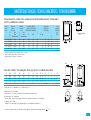
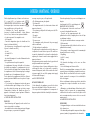
CARACTÉRISTIQUES TECHNIQUES / TECHNICAL CHARACTERISTICS / TECHNISCHE KENMERKEN
CAPACI++TÉ PUISSANCE (W) ALIMENTATION CONSOMMATION D’ENTRETIEN(1) DIMENSIONS (MM) POIDS NU
CAPACI+TY POWER (W) POWER SUPPLY CONSUMPTION FOR STEADY TEMP(1) DIMENSIONS (MM) WEIGHT EMPTY
INHOUD VERMOGEN (W) VOEDING VERBRUIK HANDHAVING TEMPERATUUR(1) AFMETINGEN (MM) NAAKT GEWICHT
(L) A.C.I.+ Blindée A.C.I.+ Blindée A* B C D E F (EN KG)
A.C.I.+ Shielded A.C.I.+ Shielded ACI+ Blindée ACI+ Blindée
(IN KG)
(l) A.C.I.+
Geblindeerde weerstand
A.C.I.+
Geblindeerde weerstand (KG)
50L 1200/1800
(2)
1200 MO MO 0,82 0,82 576 - - 35 368 156 - 22
75L 1200/2400
(2)
1200 MO MO 1,02 1,02 742 - - 35 570 120 - 27
100L 1200/2400
(2)
1200 MO MO 1,25 1,25 908 - - 35 748 113 - 32
150L 1800/3000
(2)
1600/1650 MO
(3)
MO/TC 1,59 1,75 1241 - 798 35 1048 146 - 41
200L 2400/3000
(2)
2200 MO
(3)
MO/TC 1,84 2,04 1568 - 798 35 1048 473 - 51
Verticaux muraux A.C.I.+ et blindés / A.C.I.+ and immersion element Vertical wall mounted units / Verticale muurboi-
lers A.C.I.+ en Geblindeerde weerstanden
* Hauteur sur trépied, ajouter 492 mm. (2) Puissance à l’export
* Height on tripod, add 492 mm. (2) Power for export
* Hoogte op driepoot, 492 mm. (2) Vermogen
150 1800 2200 MO
(3)
MO 1,59 1,69 1005 575 567 161 31 10 2 40
200 2400 2200 MO
(3)
MO 1,81 2,08 1260 575 567 161 31 10 2 51
250 3000 3300 MO
(3)
MO/TC 2,07 2,48 1499 575 567 161 31 10 2 57
300 3000 3300 MO
(3)
MO/TC 2,5 2,77 1761 575 567 161 31 10 2 67
500 - 5000 - TC - 4,00 Cf schéma 147
Stables A.C.I.+ et Blindés / Floor-standing units / Boilers op pootjes A.C.I.+ en Geblindeerde weerstanden
Alimentation MO : 230 V monophasé
• Alimentation TC - Tous courants, livré triphasé 400 V commutable en monophasé 230 V
(1) KWh/24h à 65°C - (1) KWh/24h at 65°C - (1) kWh/24 h bij 65 °C
Voeding MO = 230 V eenfasig
• Voeding TC = alle stroomtypes, bij de levering driefasig 400 V, overschakelbaar op eenfasig 230 V
MO power supply : 230 V single phased
• TC power supply - all types of power supplies, delivered 400 V three phase switchable to 230 V single phase
ø1”
ø1”
500L
31
678
26
25
a=45
60
ø3/4”
F
70°
74
347
ø3/4”
A
B
D
175
505
513 200L ACI+
529
230
C
E
440
315
ø3/4”
ø B
A
D
C
E
250
270*
150 à 300L
(3) Possible avec kit triphasé 400V / Possible with 400 V three-phase kit / Mogelijk een 400V driefasig onbouwkit P. 15

4
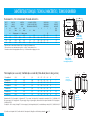
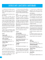
CAPACITÉ PUISSANCE (W) ALIMENTATION CONSOMMATION D’ENTRETIEN(1) DIMENSIONS (MM) POIDS NU
CAPACITY POWER (W) POWER SUPPLY CONSUMPTION FOR STEADY TEMP(1) DIMENSIONS (MM) WEIGHT EMPTY
INHOUD VERMOGEN (W) VOEDING VERBRUIK HANDHAVING TEMPERATUUR(1) AFMETINGEN (MM) NAAKT GEWICHT
(L) A.C.I.+ Blindée A.C.I.+ Blindée A B** C D E (EN KG)
A.C.I.+ Shielded A.C.I.+ Shielded ACI+ Blindée
(IN KG)
A.C.I.+
Geblindeerde weerstand
A.C.I.+
Geblindeerde weerstand (KG)
75 - 1600 - MO - 1,09 - - 580 600 - 28
100 1800 1600 MO
(3)
MO 1,28 1,24 860 600 580 600 - 32
150 1800 2200 MO
(3)
MO 1,60 1,59 1182 800 580 600 - 41
200 2100 2200 MO
(3)
MO 2,06 1,96 1509 1050 580 600 - 50
Horizontaux A.C.I.+ / A.C.I.+ Horizontal units / Horizontale boilers A.C.I.+
** Distance entre les deux étriers de fixation. Nota : voir page 9 pour fixation au sol.
** Distance between two attachment stirrups. Note : see page 9 for attachment to floor
** Afstand tussen beide bevestigingshaken. Noot: zie p. 9 wat betreft de bevestiging op de vloer.
10L sous/und/ond 2000 MO 0,63 456 255 218 262 64 7
10L sur/abov./bov. 1600 MO 0,48 456 255 289 262 64 7
15L sur/abov./bov. 2000 MO 0,53 496 287 327 294 70 9
15L sous/und/ond 2000 MO 0,66 399 338 164 345 81 9
15L sur/abov./bov. 1600 MO 0,58 399 338 236 345 81 9
30L sur/abov./bov. 2000 MO 0,76 623 338 463 345 81 12,5
50L sur/abov./bov. 2000 MO 1,13 918 338 750 345 81 17,2
Petites Capacités (sur ou sous évier) / Small tanks (above or under sink) / Kleine inhoud (boven of onder gootsteen)
100 A 200 L
75 L
90
46
691
195
Fixation Mur
Wall mounting
Wandbevestiging
Fixation Plafond
Ceiling mounting
Bevestiging aan plafond
sur évier
above sink
boven gootsteen
sous évier
under sink
onder gootsteen
CARACTÉRISTIQUES TECHNIQUES / TECHNICAL CHARACTERISTICS / TECHNISCHE KENMERKEN
Alimentation MO : 230 V monophasé / • Alimentation TC - Tous courants, livré triphasé 400 V commutable en monophasé 230 v / (1) KWh/24h à 65°C
MO power supply : 230 V single phased • TC power supply : all types of power supplies, delivered 400 V three phase switchable to 230 V single phase /
(1)
KWh/24h at 65°C
Voeding MO = 230 V eenfasig / Voeding TC = alle stroomtypes, bij de levering driefasig 400 V, overschakelbaar op eenfasig 230 V /
(1)
kWh/24 h bij 65 °C
E
D
C
184
100
A
ØB
G1/2“
E
D
C
100
A
ØB
G1/2“
(3) Possible avec kit triphasé 400V / Possible with 400 V three-phase kit / Mogelijk een 400V driefasig onbouwkit P. 15

5
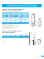
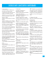
CAPACI+TÉ PUISSANCE ECHANGEUR PUISSANCE ELECTRIQUE CONSOMMATION D’ENTRETIEN** DIMENSIONS POIDS NU
(L) KW(1) W(2)(3) MM KG
CAPACI+TY EXCHANGER POWER POWER SUPPLY CONSUMPTION FOR STEADY TEMP DIMENSIONS WEIGHT EMPTY
INHOUD Vermogen warmtewisselaar VERMOGEN VERBRUIK HANDHAVING TEMPERATUUR AFMETINGEN NAAKT GEWICHT
ø A* B C D E F
75 19,3 - 1,43 505 728 320 386 490 529 - 36
100 19,3 - 1,54 505 861 498 393 497 529 - 41
150 25,6 2 400 1,76 505 1194 798 437 541 529 - 55
200 25,6 2 400 1,98 505 1521 798 437 541 529 - 63
Préparateur eau chaude sanitaire et mixte mural / Wall mounted indirect storage water heaters /
Combi boilers en Ketels met warmtewisselaars - Spiraalweerstand (wandbevostiging)
* Hauteur sur trépied, ajouter 492 mm - (1) Primaire : température 90° C, débit 2 m
3
/h - Secondaire : température 10-45° C
(2) Equipant les chaufffe-eau mixtes - (3) Kit électrique en option
* Height on tripot, add 492 mm - (1) Primary : temperature 90° C, flew2m
3
/h - Secondary temperature 10-45° C -
(2) Used on indirect storage with element - (3) Electrical kit optional
* Hoogte op driepoot, 492 mm toevoegen. - (1) Primair circuit: temperatuur 90 °C, debiet 2 m
3
/h. -
(2) Combi toestellen: geblindeerde weerstand. - (3) Option
150 30 2 400 1,76 577 1015 420 455 356 645 304 62
200 43,2 3 300 2,20 577 1270 533 543 465 645 446 73
300 49 3 300 2,97 577 1787 1006 587 489 645 490 94
Préparateur eau chaude sanitaire stable / Floor standing indirect storage water heaters /
Op pootjes ketels met warmtewisselaars spiraalweerstand
CARACTÉRISTIQUES TECHNIQUES / TECHNICAL CHARACTERISTICS / TECHNISCHE KENMERKEN
** KWh/24h à 65°C
V** kWh/24 h bij 65 °C
** KWh/24h at 65°C
eau chaude
Ø S
H
A
F
eau
froide
ØS
ØP
ØP

6
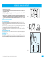
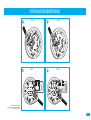
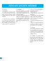
MISE EN PLACE / INSTALLATION / INSTALLATIE
• Installer l’appareil dans un local à l’abri du gel.
• Pour les appareils muraux (verticaux et horizontaux), s’assurer que la cloison est capable de supporter le
poids de l’appareil rempli d’eau.
• Si l’appareil doit être installé dans un local humide ou un emplacement dont la température ambiante est
en permanence à plus de 35°C, prévoir une aération de ce local.
• Installation dans la salle de bains : 4 volumes sont définis pour implanter des appareils suivant leurs carac-
téristiques. Nos chauffe-eau électriques peuvent être installés dans tous les volumes (hors vol. 0 = bai-
gnoire) ci-dessous référencés, selon leur classe suivant les consignes d’installation de la norme NF C15-
100, tableau 701-4 et règle 701-5. (FIG. 1)
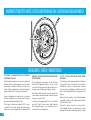
FIXATION D’UN APPAREIL VERTICAL MURAL
Chauffe-eau* et ballon à échangeur
• Laisser au dessous des extrémités des tubes de l’appareil un espace libre au moins égal 300 mm (jusqu’à
100L) / 480 mm (150 et 200L).
• Fixer l’appareil au mur par 4 boulons Ø 10 mm préalablement scellés (2 boulons seulement pour les
modèles 50, 75 et 100L).
• Les appareils peuvent être montés sur trépied (en option). Il est cependant obligatoire de fixer au mur
l’étrier supérieur de l’appareil pour éviter tout basculement.
• Il est possible de remplacer d’anciens appareils verticaux muraux sans refaire le perçage grâce à un systè-
me de pattes de transfert (disponible en option).
POSE D’UN CHAUFFE-EAU STABLE
• L’appareil doit être installé en position strictement verticale avec accessibilité à l’équipement électrique et
au groupe de sécurité.
CHAUFFE-EAU HORIZONTAL cf. Figure 2
DIFFÉRENTES POSSIBILITÉS D’INSTALLATION
ATTENTION : une fois le chauffe-eau mis en place, les têtes de raccordement hydraulique doivent impérati-
vement se trouver en position strictement verticale en dessous de l’appareil.
PETITES CAPACITÉS
Fixation murale : fixer l’étrier sur le mur à l’aide de goujons M8, préalablement scellés et d'écrous M8.
Attention : on ne peut pas mettre un chauffe-eau sur évier en lieu et place d’un chauffe-eau sous-évier
et inversement. (FIG. 3)
• Install the unit in a room protected from frost.
• For wall mounted units (vertical and horizontal), make sure that the wall is strong enough to support the
weight of the unit full of water.
• If the water heater is to be installed in a damp room or in a location in which the ambient temperature is
continuously above 35°C, then ventilate this room.
• Installation in the bathroom: four volumes are defined in which units may be installed, depending on their
characteristics. Our electric water heaters may be installed in all volumes (apart from volume 0 = bath) shown
below, in accordance with their class and with the installation instructions in NF standard C15-100, table 701-
4 and rule 701-5.
MOUNTING OF A WALL MOUNTED VERTICAL MODEL
Water heater* and exchanger tank
• Leave a free space of at least 300 mm (for 100 L models) or 480 mm (for 150 and 200 L models) below the
ends of the water heater tubes.
• Fix the unit to the wall using four Ø 10 mm bolts already anchored into the wall (only 2 bolts for 50, 75 and
100 L models).
• Units may be mounted on a tripod (optional). However, the upper stirrup of the unit must be attached
to the wall to prevent the unit from tipping.
• Old wall mounted units can be replaced without drilling new holes by using a load transfer system (available
as option).
INSTALLATION A FLOOR-STANDING WATER HEATER
• The unit must be installed in the strictly vertical position, and the electrical equipment for the safety device must
be accessible.
HORIZONTAL WATER HEARTER figure 2
SMALL TANKS
Wall attachment: fix the stirrups to the wall using M8 studs anchored to the wall and M8 nuts. Warning: an
under sink model cannot be replaced by an above sink model and vice versa. (FIG. 3)
(*hors petites capacités) / (*except for small tanks) / (*behalve kleine modellen)

7
MISE EN PLACE / INSTALLATION / INSTALLATIE
(FIG. 1)
(FIG. 2)
(FIG. 3)
• Installeer het toestel in een vorstvrije ruimte.
• Controleer voor de bevestiging van (verticale en horizontale) wandmodellen of de muur sterk genoeg is om het gewicht van het
met water gevulde toestel te dragen.
• Wordt het toestel opgesteld in een vochtige ruimte of in een ruimte waar de omgevingstemperatuur constant meer dan 35 °C
bedraagt, dan is een ventilatiesysteem noodzakelijk.
• Installatie in een badkamer: voor de opstelling van een toestel dient met 4 volumes rekening te worden gehouden, afhankelijk van
de kenmerken van het toestel. Onze elektrische boilers mogen in alle onderstaande volumes worden opgesteld (behalve in volu-
me 0 = het bad), afhankelijk van hun categorie en volgens de installatierichtlijnen van de norm NF C15-100, tabel 701-4 en regel
701-5.
BEVESTIGING VAN EEN VERTICAAL WANDMODEL
Boiler* en Ketel met warmtewisselaar
• Laat onder de uiteinden van de buizen van het toestel een ruimte van ten minste 300 mm (100 l) of 480 mm (150 -200 l) vrij.
• Bevestig het toestel aan de wand met behulp van 4 vooraf in de muur gemetste bouten Ø 10 mm (2 bouten volstaan voor de model-
len van 50, 75 en 100 l).
• De toestellen kunnen op een (afzonderlijk te verkrijgen) driepoot worden opgesteld. Het is verplicht ze in dat geval aan de muur
te bevestigen met behulp van de bovenste bevestigingshaak om omkantelen te vermijden.
• Het is mogelijk een oud verticaal wandmodel te vervangen zonder nieuwe gaten te moeten boren dankzij de (afzonderlijk te ver-
krijgen) verloophaken.
INSTALLTIE VAN EEN BOILER OP POOTJES
• Stel het toestel perfect verticaal op en zorg ervoor dat de elektrische onderdelen van het veiligheidselement vrij toegankelijk blijven.
HORIZONTALE BOILIER figuur 2
KLEINE MODELLEN
Wandbevestiging: Zet de bevestigingshaak aan de wand vast met behulp van vooraf in de muur gemetste M8 pennen en M8 moeren.
Let op! Een boiler voor boven de gootsteen mag in geen geval onder de gootsteen geïnstalleerd worden of omgekeerd. (FIG.3)
(*hors petites capacités) / (*except for small tanks) / (*behalve kleine modellen)
450
450 450

8
RACCORDEMENT HYDRAULIQUE / WATER CONNECTIONS / AANSLUITING WATERLEIDINGEN
Avant de procéd
er au raccordement hydraulique, il est
absolument indispensable de bien nettoyer les tuyaute-
ries d’alimentation afin de ne pas risquer d’introduire
dans la cuve du chauffe-eau des particules métalliques
ou autres.
ATTENTION : Ne pas raccorder directement aux cana-
lisations en cuivre les tubes eau chaude (repère rouge)
et eau froide (repère bleu) du chauffe-eau; pour éviter
les couples galvaniques fer/cuivre. Il est obligatoire
d’équiper le tube eau chaude d’un raccord diélectrique
(généralement fourni avec l’appareil hors petites capa-
cités) et le tube eau froide d’un groupe de sécurité.
En cas de corrosion des filetages des tubes non
équipés de ces protections, notre garantie ne pour-
rait être appliquée.
Quel que soit le type d’installation, elle doit comporter
un robinet d’arrêt sur l’alimentation d’eau froide, en
amont du groupe de sécurité.
Un chauffe-eau à accumulation peut être utilisé de
deux façons :
1 - sous pr
ession quand il doit desservir plusieurs postes
d’eau. L’installation doit comporter un réducteur de
pression si la pression d’alimentation est supérieure à 5
bar. Le réducteur de pression doit être monté au
départ de la distribution générale. Une pression de 3
à 4 bar est recommandée. L’installation doit être effec-
tuée avec un groupe de sécurité taré à 7 bar (non four-
ni ), neuf, de dimensions appropriées à la capaci+té
(petites capacités : 1/2”, 50 à 300l : 3/4”, 500 l : 1”),
et portant la marque NF (norme NFD 36-401).
Son installation doit être faite rigoureusement selon les
schémas ci-après (p.10). Il est obligatoire de placer le
groupe de sécurité directement sur l’entrée d’eau
froide (NFC 15-100 ch 559-3).
Before making the water connections, it is essential to
ensure that the supply pipes are thoroughly clean, to
avoid any risk of metallic or other particles entering the
water heater tank.
WARNING : do not connect water heater hot water
pipes (red mark) and cold water pipes (blue mark)
directly to copper pipes, to prevent iron-copper galva-
nic couples. The hot water pipe must be fitted with a
dielectric connector (supplied with the equipment
except for small tanks) and the cold water pipe with a
safety valve.
Our guarantee will be invalid if there is any corro-
sion on the threads of pipes not fitted with these
protectives devices.
Regardless of the installation type, it must include a
stop tap on the cold water supply, before the safety
valve.
A storage water heater may be used in two different
ways :
1 - pr
essurized when it supplies several taps. The ins-
tallation must include a pressure reducer if the supply
pressure exceeds 5 bar. The pressure reducer must
be installed at the outlet of the general distribu-
tion. A pressure of 3 to 4 bar is recommended. The
installation must be done using a new safety valve set
to 7 bar not supplied, with dimensions appropriate to
the tank (1/2" for small tanks, 3/4" for 50 to 300 L
models, and 1" for 500 l models), and bearing the NF
mark (standard NF D 36-401).
It must be installed strictly respecting the following
diagrams (p. 10). It is recommended that the safe-
ty valve should be placed directly on the cold water
inlet (NFC 15-100 ch 559-3).
Alvorens het toestel op de waterleidingen aan te slui-
ten, is het absoluut noodzakelijk de toevoerbuizen
schoon te maken om te vermijden dat metalen of
andere deeltjes in de tank van de boiler terecht komen.
LET OP ! Sluit de warmwaterbuizen (rood kenteken)
en de koudwaterbuizen (blauw kenteken) van de boi-
ler in geen geval rechtstreeks op koperen buizen aan
om te vermijden dat een galvanisch koppel
(ijzer/koper) ontstaat. Het is verplicht de warmwater-
buis van een diëlektrische koppeling te voorzien (bij
het toestel geleverd, behalve bij de kleine modellen)
en de koudwaterbuis van een veiligheidselement.
Krijgen de schroefdraden van buizen die niet met
dergelijke beveiligingen zijn uitgerust, te lijden
onder corrosie, dan geldt onze garantie niet.
Het is bij alle soorten installaties verplicht op de koud-
watertoevoer, vóór het veiligheidselement, een afsluit-
kraan te voorzien.
Een boiler kan op twee manier worden gebruikt :
1 - onder dr
uk, wanneer hij water moet produceren
dat op verschillende plaatsen kan worden afgetapt. De
installatie moet voorzien zijn van een reduceerventiel
indien de druk meer dan 5 bar bedraagt. Het redu-
ceerventiel moet gemonteerd worden aan het
begin van de algemene waterdistributie. Wij raden
een druk van 3 tot 4 bar aan. De installatie moet voor-
zien zijn van een op 7 bar getarreerd (niet bijgeleverd)
veiligheidselement dat het merkteken NF (norm NFD
36-401) draagt en waarvan de afmetingen aan de
inhoud zijn aangepast (kleine inhoud : 1/2", 50 tot
300 l: 3/4", 500 l: 1").
Bij de installatie dienen de schema's op p. 10 nauw-
keurig in acht te worden genomen. Het is verplicht
het veiligheidselement rechtstreeks op de koudwa-
tertoevoer te plaatsen (NFC 15-100 ch 559-3).

9
RACCORDEMENT HYDRAULIQUE / WATER CONNECTIONS / AANSLUITING WATERLEIDINGEN
- En outre, il ne faut absolument pas qu’en cas de sur-
pression, l’écoulement en résultant puisse être freiné.
Ceci implique que le tube de vidange ait une pente
continue et suffisante, et un diamètre adapté au débit.
2 - en écoulement libr
e, pour alimenter un seul point
d’eau : Ce type d’installation est spécialement adapté
aux chauffe-eau de la gamme des petites capacités de
10, 15, 30 et 50 L, sur-évier et sous-évier suivant les
modèles, lorsqu’ils ne peuvent être installés sous pres-
sion. L’installation doit être réalisée avec un robinet
mélangeur spécifique. Dans ce cas, il n’y a pas lieu
d’utiliser un groupe de sécurité.
Attention, il est normal que cela goutte par la
robinetterie, lors des périodes de chauffe. Ne pas
obstruer l’écoulement.
- Furthermore, if there is an overpressure, the resulting
flow must never be hindered. This means that the
drain pipe should have a continuous and sufficient
slope, and its diameter should be appropriate for the
flow.
During heating periods, the water contained in the
tank expands and some will escape as a slow stream by
draining (about 3% of the capaci+ty for each heating
cycle). This is nothing to worry about, this phenome-
non is absolutely normal.
It is recommended that a retention tank should be pla-
ced under the water heater with drainage if the tank is
installed on an upper floor.
2 - in fr
ee flow, when only a single water tap is to be
supplied. This type of installation is specifically adap-
ted to point-of-use water heaters (i.e. capacities of 10,
15, 30 and 50 L) that cannot be installed as unvented
systems (i.e. pressurised). The installation must be
made with a special mixing tap. In this case there is
no need for a safety valve.
- Bovendien mag het wegvloeiend water bij overdruk
in geen geval worden afgeremd. Dat betekent dat de
aftapbuis constant en op toereikende wijze moet afhel-
len en dat de diameter geschikt moet zijn voor het
debiet.
Tijdens het opwarmen zet het water in de tank uit en
een deel van dat water ontsnapt druppelsgewijze via
de afvoergoot (ongeveer 3 % van de inhoud per ver-
warmingscyclus). U hoeft zich daar geen zorgen over
te maken: dit is een heel normaal verschijnsel.
Wordt het toestel in de hoogte geïnstalleerd, dan is het
raadzaam een vergaarbak met een afvoergoot onder
de boiler te monteren.
2 - met een spontane waterafvoer
, voor één enkele
waterkraan. Dit soort installatie is speciaal aangepast
voor de kleine inhoud boilers van 10, 15, 30 en 50
liters, boven en onder de gootsteen volgens de model-
len, toen ze kunnen niet onder druk geplaatst worden.
In dit geval is de installatie van een specifieke meng-
kraan noodzakelijk; een veiligheidselement is echter
overbodig.

10
RACCORDEMENT HYDRAULIQUE / WATER CONNECTIONS / AANSLUITING WATERLEIDINGEN
A
B
C
D
2
3
4
5
6
1
7
ECOULEMENT LIBRE (*)
FREE FLOW (*)
S
PONTANE AFVOER (*)
6
7
1
2
5
SOUS PRESSION (*)
MAINS PRESSURE (*)
O
NDER DRUK (*)
4
3
7
1
5
VERTICAUX MURAUX
VERTICAL WALL MOUNTED
VERTICALE WANDMODELLEN
3
4
6
2
Arrivée eau froide / Cold water inlet / Koudwatertoevoer
Robinet d’arrêt / Stop tap/ Afsluitkraan
Réducteur de pression éventuel / Pressure reducer if necessary / Eventueel reduceerventiel
Groupe de sécurité / Safety valve / Veiligheidselement
Entonnoir / Funnel / Trechter
Départ eau chaude / Hot water outlet / Warmwaterafvoer
Manchon diélectrique obligatoire / Compulsory dielectric connection / Verplichte diëlektrische mof
1
2
3
4
5
6
7
* Ces schémas montrent l’installation des appa-
reils sous évier.
Pour les modèles sur-évier, les raccordements
sont sous l’appareil comme dans le cas des
appareils muraux.
** Les appareils équipés d’un échangeur ser-
pentin doivent être installés en position verti-
cale, avec une pompe de charge (cf fig. 1)
* These diagrams show the installation of
under sink models.
Connections for above sink models are
under the water heater as in the case of wall
mounted equipment.
** Vertical wall mounted and horizontal water
heaters may also be mounted in series using
the same principale.
* Deze schema's illustreren de installatie van
toestellen onder de gootsteen.
De installatie van toestellen voor boven de
gootsteen is dezelfde als bij wandmodellen.
** De verticale en horizontale wandmodellen
kunnen ook volgens hetzelfde principe in
serie gemonteerd worden.
Arrivée d’eau froide
Cold water inlet/ Koudwatertoevoer
Départ eau chaude sanitaire
Domestic hot water outlet / Afvoer warm water voor sanitair
Retour chauffage
Heating return / Retour verwarming
Départ chauffage
Heating outlet / Afvoer verwarming
Purgeur automatique / Automatic purge /
Automatische aftapkraan
Clapet anti-retour / Non-return valve /
Terugslagklep
Pompe de charge / Pressurizing pump / Circulatiepomp
Raccordement par flexible / Flexible connection / Aansluiting
Aquastat commande pompe de charge (option) / Pumpthermostat (optional) /
Thermostaat pomp (option)
(FIG. 1)**
1
Kit Pompe de charge / Kit pomp / Kit pump
- Electrical connection
Thermostat / pump
- Elektrische armsluiting
Thermostat / pomp
Thermostat / pump
C
D
Liaison électrique
aquastat/pompe
1
2
5
3
4
B
A
400 mm
mini

11
RACCORDEMENT HYDRAULIQUE / WATER CONNECTIONS /AANSLUITING WATERLEIDINGEN
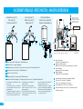
INFORMATIONS COMPLEMENTAIRES
POUR LES P.E.C.S.
(FIG. 1)
Ces appareils possèdent :
- Un circuit primaire qui doit être fermé par raccordement à une sour-
ce de chaleur, telle que chaudière de chauffage central. La pression de
service de ce circuit ne devra pas excéder 3 bar et sa température
100°C (entrée et sortie de ce circuit repérées en blanc sur l’extrémité
ou sur le côté - Ø 1” femelle).
- Un circuit secondaire pour l’eau chaude sanitaire (entrée de l’eau froi-
de repérée en bleu et sortie de l’eau chaude repérée en rouge).
Le raccordement à l’installation de chauffage central s’effectue au
moyen de tubes d’un diamètre intérieur minimum de 20 mm. Utiliser
de préférence des tubes en aci+er pour éviter tout risque de corrosion
et en intercalant une vanne de sectionnement. L’appareil est pourvu
d’un doigt de gant pour placer la sonde régulant le circuit primaire (en
option).
Dans le cas où des vannes de sectionnement sont intercalées, il est
impératif de laisser ces vannes ouvertes afin d’éviter les surpressions à
l’intérieur du serpentin.
1
re
mise en service
Remplir impérativement le circuit primaire en premier (circuit connec-
té à la chaudière)
• ouvrir le robinet d’eau de ville, dévisser le purgeur d’air afin d’évacuer
l’air introduit par l’opération de remplissage
• mettre la pompe de charge en marche quelques instants afin d’accé-
lérer l’opération de dégazage.
ATTENTION MODELES A.C.I.
(uniquement pour les préparateurs d’eau chaude sanitaire)
les appareils à échangeur serpentin sont protégés contre la corrosion
par un système électronique (système A.C.I.) qui doit être alimenté
sous 230 V 24 h/24 pendant les périodes d’utilisation. En cas d’absen-
ce prolongée, il est possible de couper l’alimentation.
Le branchement du système A.C.I. s’effectue par la connexion du câble
de raccordement fourni et précablé sur l’appareil. Utiliser une alimen-
tation indépendante qui est continuellement sous tension. La garantie
dépend du bon raccordement du système. Un petit voyant lumineux
clignotant vous indique que le système est sous tension.
ADDITIONAL INFORMATION FOR INDIRECT
STORAGE WATER HEATERS
(FIG. 1)
These water heaters have:
- A primary circuit that must be closed by connection to a heat source,
such as a central heating boiler. The working pressure in this circuit
must not exceed 6 bar and its temperature must not exceed 100°C
(inlet and outlet for this circuit marked in white on the end or on the
side - Æ 1" female fitting).
- A secondary circuit for domestic hot water (cold water inlet marked in
blue and hot water outlet marked in red).
The first step is to supply the primary circuit, and then the secondary
circuit, with water.
The connection to the central heating installation is made using pipes
with a minimum inside diameter of 20 mm. Use steel tubes in prefe-
rence to prevent any risk of corrosion, and include an isolating valve.
The unit is provided with a well in which the probe regulating the pri-
mary circuit can be placed (optional).
If isolating valves are inserted, it is essential that these valves should be
left open to avoid overpressures inside the coil.
1st star
t up:
The primary circuit must be filled first (circuit connected to the boiler)
• Open the town water tap, unscrew the air purge to allow air that
entered during the filling operation to escape.
• Start up the pressurizing pump for a few minutes in order to accele-
rate the degassing operation.
WARNING A.C.I. MODELS
(Indirect storage water heaters solely)
Water heaters with concentric coil heat exchangers are protected
against corrosion by an electronic system (A.C.I. system) that must be
powered at 230 V for 24 hours per day during usage periods. The
power supply can be switched off if the premises are vacant for a long
period.
The A.C.I. system is plugged in using the connecting cable supplied
and pre-wired onto the water heater. Use an independent power sup-
ply that is never switched off. The guarantee will be null and void if the
system is not properly connected. A small flashing light indicator
informs you that the system is switched on.
BIJKOMSTIGE INFORMATIE M.B.T. DE
COMBI BOILERS
(FIG. 1)
Deze toestellen zijn voorzien van:
- Een primair circuit dat gesloten moet zijn door aansluiting op een warm-
tebron, bij voorbeeld op de verwarmingsketel van de centrale verwarming.
De bedrijfsdruk van dit circuit mag niet meer bedragen dan 6 bar en de
temperatuur 100 °C (in- en uitgang van dit circuit zijn in het wit aangeduid
op het uiteinde of aan de zijkant - Ø 1" wartelring).
- Een secundair circuit voor het warm water voor het sanitair (koudwater-
toevoer aangeduid in het blauw en warmwaterafvoer in het rood).
Eerst moet het primair circuit van water voorzien worden en daarna het
secundair circuit. De aansluiting op de centrale verwarmingsinstallatie
gebeurt met behulp van buizen met een binnendiameter van ten minste
20 mm. Gebruik bij voorkeur stalen buizen om corrosieverschijnselen te
vermijden en monteer tussenin een afsluitschuif.
Het toestel is voorzien van een taster om de sonde die het primair circuit
regelt, te plaatsen (en option).
Eventueel tussengeschakelde afsluitschuiven moeten open blijven om
overdruk in de spiraal te vermijden.
1ste indienstneming:
Vul in ieder geval eerst het primair circuit (het circuit dat op de verwar-
mingsketel is aangesloten).
• Draai de hoofdwaterkraan open en draai de ontluchtingskraan los om de
tijdens het vullen binnengestroomde lucht te verwijderen.
• Schakel de circulatiepomp enkele ogenblikken in om het ontluchten te
versnellen.
LET OP A.C.I .
(M.B.T. de combi boilers tijdens)
De toestellen met een spiraalwisselaar zijn voorzien van een elektronisch cor-
rosie werend veiligheidssysteem (het A.C.I. syteem); dit systeem moet tijdens
het gebruik 24 uur per dag op een 230 V net aangesloten blijven. Bent u vrij
lang afwezig, dan kan de stroom onderbroken worden.
Het A.C.I. systeem wordt aangesloten d.m.v. het bijgeleverde en voorbe-
kabelde snoer. Gebruik een afzonderlijke voeding die constant onder span-
ning staat. De garantie is slechts geldig indien het systeem behoorlijk is aan-
gesloten. Een knipperend controlelampje wijst erop dat het systeem onder
spanning staat.

12
Le chauffe-eau ne peut être branché et fonctionner que sur un réseau à
courant alternatif.
ATTENTION : LE RACCORDEMENT DE L’ALIMENTATION S’EFFECTUE
SUR LE BORNIER POUR LES MODÈLES AVEC BORNIER, SUR L’ENTRÉE
DU THERMOSTAT POUR LES MODÈLES SANS BORNIER ET EN
AUCUN CAS SUR LA RESISTANCE OU À LA SORTIE DU THERMO-
STAT. AUCUNE INTERVENTION SUPPLEMENTAIRE N’EST A PREVOIR
EXCEPTÉS LES CHANGEMENTS DE COUPLAGE SI NECESSAIRE. POUR
LES CHAUFFE-EAU A.C.I.+, LE CIRCUIT A.C.I.+ EST PRÉCABLÉ EN
USINE.
• Si le chauffe-eau est un modèle «Tous Courants», veiller à ce que le
câblage électrique de l’appareil soit adapté à la tension
d’alimentation du réseau.
• Le chauffe-eau doit être relié à une canalisation fixe ou une gaine anne-
lée normalisée jusqu’au logement calibré du capot par un câble rigide
(section des conducteurs : minimum 2,5 mm2 et 4 mm2 sur le 500L).
• La mise à la terre est obligatoire. Une borne spéciale portant le repère
est prévue à cet effet.
• L’installation doit comporter en amont du chauffe-eau un dispositif de
coupure omnipolaire avec une distance d’ouverture des contacts d’au
moins 3 mm.
Dans le but d’optimiser la consommation d’énergie, le thermostat a été
réglé pour que la température de l’eau dans le chauffe-eau soit limitée à
65° C (± 5°C) ; la résistance à la corrosion et à l’entartrage s’en trouve
améliorée.
Le thermostat ne doit sous aucun pretexte subir d’éventuels réglages ou
réparations en dehors de nos usines à l’exception du réglage normal par
rotation de l’index (qui ne peut être effectué que par l’installateur après
mise hors tension de l’appareil). Le non respect de cette clause suppri-
me le bénéfice de la garantie.
PETITES CAP
ACITÉS : Le thermostat est réglé en usine à 65°C (± 5°C). Il
vous est possible de modifier ce réglage par la molette du thermostat.
Diminuer la température de réglage contribue à diminuer les dépôts de
calcaire. Le témoin de fonctionnement reste allumé uniquement pendant
la phase de chauffe.
COUPE-CIRCUIT THERMIQUE :
Tous nos chauffe-eau sont équipés d’un coupe-circuit de sécurité qui
déclenche l’arrêt du chauffe-eau si la température atteint accidentelle-
ment une valeur exagérée. En cas de déclenchement de la sécurité, COU-
PER LE COURANT AVANT TOUTE OPÉRATION, vérifier l’installation avant
de procéder à son réarmement. Rétablir le courant. En cas de déclenche-
ment répétitif, faire remplacer le thermostat par une personne habilitée.
BRANCHEMENT ÉLECTRIQUE*/ ELECTRICAL CONNECTIONS*/ELEKTRISCHE AANSLUITINGEN *
(CONFORME NFC 15-100)
The water heater can only be connected to and operate on an AC
network.
WARNING: THE POWER SUPPLY IS CONNECTED TO THE TERMI-
NAL BLOCK FOR MODELS WITH A TERMINAL BLOCK, TO THE
THERMOSTAT INPUT FOR MODELS WITHOUT A TERMINAL
BLOCK, AND NEVER TO THE ELEMENT OR THE THERMO-
STAT OUTPUT. NO ADDITIONAL WORK IS REQUIRED, EXCEPT
FOR COUPLING CHANGES IF NECESSARY. THE A.C.I.+ CIRCUIT
ON A.C.I.+ MODELS IS PREWIRED IN THE FACTORY.
• If the water heater is an "All Currents" model, check that its electric
wiring is correctly adjusted for the network power supply voltage.
• The water heater must be connected to a fixed pipe through a
rigid cable (minimum conductor cross-section = 2.5 mm≈ or 4
mm2 for the 500 l tank).
• Earthing is compulsory. A special terminal marked is pro-
vided for this purpose.
• The installation must include an all-pole circuit breaking device
before the water heater, with a contact opening distance of at
least 3 mm.
The thermostat was set so that the water temperature in the water
heater is limited to 65°C (± 5 °C) in order to optimize energy
consumption; this improves resistance to corrosion and to scaling.
The thermostat must not be modified or repaired in any way out-
side our factories for any reason whatsoever, except for normal
adjustment by rotating the index (which should only be done by
the installer after switching the equipment off). Failure to respect
this clause will invalidate the guarantee.
SMALL
TANKS : The thermostat is set to 65°C (±5°C) in the fac-
tory. You can modify this setting using the knurled knob on the
thermostat. Reducing the temperature will help to reduce deposi-
ted scale. The operating light remains on only during the heating
phase.
TEMPERATURE CIRCUIT BREAKER :
All our water heaters are equipped with a safety temperature cir-
cuit breaker that switches the water heater off if the temperature
accidentally reaches an excessively high value. If the safety device
trips, SWITCH OFF THE POWER BEFORE DOING ANYTHING, and
then check the installation before resetting it. Switch the power
on again. Have the thermostat replaced by a professional if it trips
repeatedly.
NEVER SHORT CIRCUIT THE SAFETY DEVICE.
De boiler mag uitsluitend worden aangesloten op wisselstroom.
LET OP ! BIJ DE MODELLEN MET EEN AANSLUITKLEMMENBLOK MOET
HET SNOER OP HET AANSLUITKLEMMENBLOK WORDEN AANGESLO-
TEN, BIJ MODELLEN ZONDER AANSLUITKLEMMENBLOK OP DE
INGANG VAN DE THERMOSTAAT. IN GEEN GEVAL OP DE WEERSTAND
OF OP DE UITGANG VAN DE THERMOSTAAT. VERDER BLIJFT DE ELEK-
TRISCHE INSTALLATIE ONGEWIJZIGD, BEHALVE INDIEN DE KOPPELING
VERANDERD DIENT TE WORDEN. BIJ A.C.I.+ BOILERS IS HET A.C.I.+ CIR-
CUIT IN DE FABRIEK VOORBEKABELD.
• Is de boiler een TC-model (alle stroomtypes), controleer of de elek-
trische draden aan de netspanning zijn aangepast
• De boiler moet op een vaste leiding zijn aangesloten d.m.v. een
onbuigzame kabel (doorsnede van de geleiders: minimum 2,5 mm≈ en
4 mm≈ bij het model 500 l).
• De aarding van het toestel is verplicht. Daarvoor is een specifieke aans-
luitklem voorzien .
• De installatie moet stroomopwaarts van de boiler voorzien zijn van een
schakelaar voor alle polen met contactopeningen van ten minste 3 mm.
Om het energieverbruik te optimaliseren werd de thermostaat zo afges-
teld dat de temperatuur van het water in de boiler beperkt blijft tot
65 °C (± 5 °C); zo blijft de weerstand beter bestand tegen corrosie en kal-
kaanslag.
De thermostaat mag in geen geval worden bijgesteld of hersteld buiten
onze fabrieken; alleen de normale afstelling door de installateur is toe-
gestaan, d.w.z. dat alleen hij de wijzer na uitschakeling van het toestel
mag verdraaien. Door niet-naleving van deze clausule vervalt de
garantie.
Verwarmingsketels met een kleine capaci+teit: de thermostaat is in fabriek
afgesteld op 65°C (±5°C). U kunt deze afstelling wijzigen met behulp van
het kartelwieltje op de thermostaat. Een lager afgestelde temperatuur leidt
tot minder kalkaanslag. Het werkingscontrolelampje brandt uitshuitend
tijdens het verwarmen.
THERMISCHE BEVEILIGING:
Al onze boilers zijn voorzien van een beveiliging die de boiler uitschakelt
zodra per ongeluk een overdreven temperatuur wordt bereikt. Treedt het
veiligheidssysteem in werking, ONDERBREEK IN DE EERSTE PLAATS DE
STROOM; de installatie mag pas na een grondige controle opnieuw
gereset worden. Schakel het toestel opnieuw in. Doet het probleem zich
opnieuw voor, raadpleeg een bekwaam technicus om de thermostaat te
laten vervangen.
HET VEILIGHEIDSSYSTEEM MAG IN GEEN GEVAL KORTGESLOTEN WORDEN

13
BRANCHEMENT ÉLECTRIQUE*/ ELECTRICAL CONNECTIONS
(CONFORME NFC 15-100)
EN AUCUN CAS ON NE DOIT COURT-CIRCUITER LA SÉCURITÉ
ACI+ : en cas de déclenchement en sécurité, remplacer le bloc thermo-
stat eléctronique.
PETITES CAP
ACITÉS : Pour réarmer la sécurité, il est nécessaire de retirer le
capot, ensuite, appuyer sur le bouton safety du thermostat. Après avoir
réenclenché la sécurité, remettre le capot et rétablir le courant. En cas de
déclenchement répété, demander l’intervention d’une personne habilitée.
* NOTA : ne concerne pas les ballons à échangeur. Il est cependant obligatoire
de raccorder ce type d’appareils à la terre.
* NOTE: Not applicable to tanks with heater exchanger. However, this type of heater must be earthed.
* NOOT: dit geldt niet voor de ketels met warmtewisselaars. Het is echter verplicht deze toestellen
te aarden.
ACI+ : If the security system set off, change the electronique ther-
mostat.
SMALL TANKS: The safety device is reset by moving the cover,
and then pressing on the safety button of the thermostat. After
resetting the safety device, put the cover back on and switch the
power on again. Have the thermostat replaced by a professional
if it trips repeatedly.
ACI +: Als het veiligheidssysteem in werking treedt, het electronische
thermostaatblok vervangen.
KLEINE MODELLEN:
Om het veiligheidssysteem te resetten is het nood-
zakelijk de kap die toegang geven tot het veiligheidssysteem, te verwij-
deren om vervolgens de safety knop van de thermostaat in te drukken.
Na het veiligheidssysteem opnieuw te hebben ingeschakeld, de kap
opnieuw aanbrengen en het toestel inschakelen. Treedt het veiligheid-
ssysteem opnieuw in werking, raadpleeg een bekwaam technicus.

Verticaux muraux mono
Single phase wall mounted vertical models
Verticale muurboilers eenf.
Horizontaux
Horizontal models
Horizontale modellen
Horizontaux
Stables floor-standing
Op pootjes
OBLIGATION :
Pour bénéficier de la garantie,
il est obligatoire de brancher
le système A.C.I.+
OBLIGATION :
You must plug in the A.C.I.+
system otherwise the
guarantee will not be valid.
VERPLICHT :
Om van de garantie gebruik te
kunnen maken dient u verplicht
het A.C.I.+ systeem aan te sluiten.
14
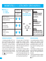
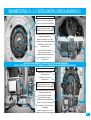
BRANCHEMENT ÉLECTRIQUE A.C.I.+ / A.C.I.+ ELECTRICAL CONNECTION / ELEKTRISCHE AANSLUITINGEN A.C.I.+
■ MODELES A.C.I.+
A.C.I.+ MODELS
A.C.I.+ MODELLEN
ALIMENTATION
POWER SUPPLY /VOEDING
MONO 230 V
230 V SINGLE PHASE
EENFASING 230 V.
A B
C D
C D
+
+
+
PROCEDURE DE RACCORDEMENT
• Ce chauffe-eau est pré-câblé en 230 V~ mono-
phasé. Pour du 400 V~ triphasé vous devez rem-
placer la platine monophasée d’origine par un
kit triphasé 400V~. La procédure d’installation
de ce kit est détaillée dans la notice joint au kit.
• Raccorder les extrémités du câble sur le ther-
mostat, aux bornes à vis prévues à cet effet (le
démontage du thermostat n’est pas nécessaire).
• Raccorder le fil de terre vert/jaune sur la borne
repère , sur la porte du chauffe-eau.
Voir photos p.15
CONNECTION PROCEDURE
• The original connection for this water heater is
configured for 230 V~ single phase. For a 400 V~
three-phase connection you need to replace the
original single phase plate by a 400 V~three-phase
kit. Refer to the manual enclosed with the kit for
instructionss for installation.
• Connect the ends of the thermostat cables to
the screw terminals provided for this purpose
(there is no need to disassemble the thermostat).
• Connect the yellow/green earthing wire to the
terminal marked with the earthing symbol on the
door of the water heater. See pictures p.15
CONNECTION PROCEDURE
• De oorspronkelijke aansluiting voor deze boiler
is geschikt voor 230 V~ éénfasig. Voor een 400
V~ driefasige aansluiting dient u de oorspronkelij-
ke éénfaseplaat vervangen door een 400 V~ drie-
fasige ombouwkit. Zie handleiding ombouwkit
voor installatie.
• Sluit de uiteinden van de kabel aan op de ther-
mostaat, op de twee hiervoor bestemde schroefk-
lemmen (het is niet nodig the thermostaat te
demonteren).
• Sluit de groen/gele aardleiding aan op de plaats
met het aardesymbool op de deur van de boiler.
p. 15
Règlage de la température
de l’eau /
Water temperature setting /
Instelling watertemperatuur

15
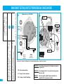
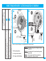
BRANCHEMENT ÉLECTRIQUE A.C.I.+ / A.C.I.+ ELECTRICAL CONNECTION / ELEKTRISCHE AANSLUITINGEN A.C.I.+
AB
C
D
Borne de terre / Earthing terminal / Aardingsklem
Filerie de l’ACI / ICA wiring / Bedrading ACI
Voyant ACI / ICA pilot light / ACI signaalampje
Bornier d’alimentation (non polarisé) /
Supply terminal (not polarized) /
Stroomvoedingsklem (niet gepolariseerd)
Filerie élément chauffant / Heating element wiring
Bedrading verwarmingselement
Règlage de la température de l’eau / Water
temperature setting / Instelling watertemperatuur
Element chauffant / Heating element /
Verwarmingselement
Connecteur filerie élément chauffant /
Heating element wiring connector /
Aansluitklem bedrading verwarmingselement
Sonde température / Heat sensor /
Temperatuursensor
Borne de terre / Earthing terminal / Aardingsklem
Element chauffant / Heating element /
Verwarmingselement
Sonde température / Heat sensor /
Temperatuursensor
Bornier d’alimentation (non polarisé) /
Supply terminal (not polarized) /
Stroomvoedingsklem (niet gepolariseerd)
Filerie élément chauffant / Heating element wiring
Bedrading verwarmingselement
Connecteur filerie élément chauffant /
Heating element wiring connector /
Aansluitklem bedrading verwarmingselement
Filerie de l’ACI / ICA wiring / Bedrading ACI
Voyant de chauffe ACI / ACI pilot light heating /
ACI signaalampje
Règlage de la température de l’eau / Water
temperature setting / Instelling watertemperatuur
EFFECTUER LE RACCORDEMENT DE L’ALIMENTATION SUR LE BORNIER UNIQUEMENT /
CONNECT THE POWER SUPPLY ONLY VIA THE TERMINAL / DE STROOM ENKEL OP DE KLEMMENSTROOL ANSLUITEN

16
BRANCHEMENT ÉLECTRIQUE MIXTES ET PREPARATEURS EAU CHAUDE SANITAIRE
ALIMENTATION
POWER SUPPLY / VOEDING
MONO / SINGLE PHASE/ EENF.
Préparateur eau chaude sanitaire vertical mural
Indirect storage wall mounted
Ketels met warmtewisselaars wandmodel
Préparateur eau chaude sanitaire stable
Indirect storage floor standing
Op pootjes ketels met warmtewisselaars
J1
K1
1- Ph : Phase alimentation
2- S : Pompe «Circuit sanitaire»
3- Ch : Pompe «Circuit Chauffage
J1
K1
* Und Ketels met warmtewisselaars
OBLIGATION : Pour bénéficier de la garantie, il est obligatoire de brancher
le système A.C.I.
OBLIGA
TION : You must plug in the A.C.I. system otherwise the guarantee
will not be valid.
VERPLICHT :
Om van de garantie gebruik te kunnen maken dient u
verplicht het A.C.I. systeem aan te sluiten.
(75-200 L)
(150-300 L)
(Uniquement sur 150-200L)
Commande de pompe
Commande
de pompe
Alimentation 230V pompe
Alimentation
230V pompe
Câble non fourni
N
N
N
L
N
L
N
L
N
CABLE
ALIMENTATION
ACI+
A ALIMENTER
24H/24
CABLE
ALIMENTATION
ACI A ALIMENTER
24H/24
L
Câble non fourni
Câble non fourni
Câble non fourni
POMPE
CHAUFFAGE
Heating pump
Verwarming pomp
POMPE
CHAUFFAGE
Heating pump
Verwarming
pomp
POMPE ECS
DHW pump
Pomp
warmtewisselaar
POMPE ECS
DHW pump
Pomp
warmtewisselaar
Pas de triphasé / No Three phase / Niet drief.
Schémas non contractuels / Diagrams not contractually binding / Niet contractuele schema’s
A.C.I.

17
INDIRECT STORAGE WATER HEATERS* / ELECTRISCHE AANSLUITIGEN ACI COMBISPIRAAL*
Schémas non contractuels / Diagrams not contractually binding / Niet contractuele schema’s
N1
L1
1- Ph : Phase alimentation
2- S : Pompe «Circuit sanitaire»
3- Ch : Pompe «Circuit Chauffage
OBLIGATION : Pour bénéficier de la garantie, il est obligatoire de brancher
le système A.C.I.
OBLIGA
TION : You must plug in the A.C.I. system otherwise the guarantee
will not be valid.
VERPLICHT :
Om van de garantie gebruik te kunnen maken dient u
verplicht het A.C.I. systeem aan te sluiten.
Alimentation 230V stéatite
Câble non fourni
NL
Commande de pompe
Cable non fourni
POMPE ECS
DHW pump
Pomp
warmtewisselaar
POMPE ECS
DHW pump
Pomp
warmtewisselaar
CABLE ALIMENTATION
ACI A ALIMENTER
24H/24
INTERRUPTEUR
ETE / HIVER
Alimentation 230V pompe
Cable non fourni
ALIMENTATION
POWER SUPPLY / VOEDING
MONO / SINGLE PHASE/ EENF.
Chauffe-eau mixtes ACI vertical mural
Indirect storage with element wall mounted
Combispiraal ACI wandmodel
Préparateur eau chaude sanitaire vertical mural magnésium
Indirect storage wall mounted magnesium
Ketels met warmtewisselaars wandmodel
L1
N1
* Und Ketels met warmtewisselaars
(75-200 L)
Pas de triphasé / No Three phase / Niet drief.
Alimentation 230V pompe
Câble non fourni
Câble non fourni
POMPE
CHAUFFAGE
Heating pump
Verwarming pomp

18
Verticaux muraux 50-200L mono
50-200L vertical wall mounted models single phase
Verticale muurboilers 50-200 l eenf.
Horizontaux 75, 100, 150, 200L mono
75-200L horizontal models single phase / Horizontale modellen 75-200 l
Stables 150, 200, 250 et 300L
150 - 300L floor-standing single phase / Op pootjes 150 - 300 l
Verticaux muraux 150 et 200L tous courants
150 and 200L vertical wall mounted all powers
Verticale muurboilers 150 en 200 l alle stroomtypes
Stables 200, 250 et 300L
200, 250 and 300L floor-standing / Op pootjes 200, 250 en 300 l
Stable 500L / 500L floor-standing / Op pootjes 500 l
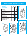
BRANCHEMENT ÉLECTRIQUE BLINDÉ / IMMERSION ELEMENT ELECTRICAL CONNECTION
A
A
A1
B1
C2
C1
D2
D1
B2
230 V
A1
* Passage de tri en mono : raccordement des fils noirs à modifier comme indiqué sur le schéma.
* Change from 3-phase to single phase : connection of black wires to be modified as shown on the drawing.
* Overschakeling van drief. naar eenf.: wijzig de aansluiting van de zwarte draden volgens het schema.
*
*
*
Schémas non contractuels
Diagrams not contractually binding
Niet contractuele schema’s
■ MODELES BLINDÉS
SHIELDED MODELS
GEBLINDEERE MODELLEN
ALIMENTATION
POWER SUPPLY / VOEDING
MONO TRIPHASE
SINGLE PHASE/ EENF. THREE PHASE/DRIEF.
230 V
400 V
B2
230 V
B1
*
Eau chaude
Hot water
Warm water
Eau froide
Cold water / Koud water
Eau chaude
Hot water
Warm water
Eau froide
Cold water
Koud water

230 V
230 V
Schémas non contractuels
Diagrams not contractually binding
Niet contractuele schema’s
ELEKTRISCHE AANSLUITINGEN GEBLINDEERDE MODELLEN
C1
C2
A1
A2
A3
B1
B2
B3
P
1
P
2
P
3
D1
D2
400 V
400 V
19

20
BRANCHEMENT ÉLECTRIQUE PETITES CAPACITÉS / ELECTRICAL CONNECTION FOR SMALL TANKS / ELEKTRISCHE AANSLUITINGEN KLEINE MODELLEN
MISE EN SERVICE / START UP / INDIENSTSTELLING
ATTENTION : NE JAMAIS METTRE SOUS TENSION LE
CHAUFFE-EAU SANS EAU.
Avant de mettre le chauffe-eau sous tension, le remplir com-
plètement d’eau en ayant auparavant ouvert les robinets
d’eau chaude ; ne refermer les robinets que lorsque l’écou-
lement s’effectue régulièrement et sans bruit de tuyauterie
(purge complète de l’air et nettoyage des tuyauteries).
Lorsque le remplissage est terminé, mettre le contacteur
électrique en marche forcée et attendre environ 30 minutes
(pression de l’installation atteignant 7 bar).
Vérifier, pour les chauffe-eau équipés de l’A.C.I.+, que le
voyant A.C.I. vert fonctionne au plus tard 15 minutes après
la mise sous tension, cela garantit le bon fonctionnement de
WARNING : NEVER SWITCH THE WATER HEATER ON
WITH NO WATER.
Before switching the water heater on, open hot water
taps and fill it completely with water; do not close the
valves until flow takes place uniformly and there are no
more pipe noises (all air purged and pipes cleaned).
When filling is finished, put the electrical contactor into
forced operation and wait for about 30 minutes (installa-
tion pressure reaches 7 bar)
For water heaters equipped with A.C.I.+, check that the
green A.C.I.+ light it works not more than 15 minutes
after switching the power on, to ensure that the corro-
sion protection is working properly.
LET OP ! ZET EEN LEGE BOILER NOOIT ONDER
SPANNING !
Zet de boiler pas onder spanning nadat hij volledig met
water gevuld is: laat hem vollopen door eerst de warm-
waterkranen te openen en opnieuw dicht te draaien
zodra het water er regelmatig en geluidloos uit stroomt
(d.w.z. na het volledig ontluchten en reinigen van de lei-
dingen).
Wanneer de boiler gevuld is, zet de schakelaar handma-
tig op AAN en wacht een 30-tal minuten (de druk in de
boiler bereikt dan 7 bar).
Bij een A.C.I.+ boiler, controleer of het groene A.C.I.+
controlelampje ten laatste een kwartier na het onder
spanning zetten begint in werking zijn: dit wijst erop dat

MISE EN SERVICE / START UP /INDIENSTSTELLING
la protection contre la corrosion.
Le voyant A.C.I. doit fonctionner 24 heures / 24 , quel que
soit le système d’alimentation choisi pour l’installation (tarif
jour/nuit). Vert = ACI / Orange = ACI+ CHAUFFE
Avant de raccorder définitivement l’appareil, vérifier qu’il
est plein d’eau. Si ce n’est pas le cas, l’alimentation élec-
trique du chauffe-eau ne peut pas s’effectuer (Anti-chauffe
à sec).
Pendant les périodes de chauffe, l’eau contenue dans la
cuve se dilate et une partie de cette eau s’échappe sous
forme de filet par la vidange (environ 3% de la capaci+té
par cycle de chauffe). Il n’y a pas lieu de s'inquiéter, ce phé-
nomène est absolument normal.
Dans le cas d’une installation en étage, il est conseillé de
mettre un bac de rétention sous le chauffe-eau avec éva-
cuation.
Pour une eau présentant des teneurs en TH 20°f, il est
recommandé de traiter celle-ci. Dans le cas d’un adoucis-
seur, la dureté de l’eau doit rester supérieure à 12°f.
▲ Vérifier que :
- Le robinet de vidange du groupe de sécurité fonctionne
bien, le basculer de la position vidange à la position arrêt et
reciproquement afin d’éliminer tous les déchets éventuels.
- Le joint de bride est bien étanche, resserrer raisonnable-
ment si nécessaire. (Serrer les écrous en vis à vis; muraux
maxi 0,8kg.m, stables et horizontaux 0,6kg.m et petites
capacités 0,8kg.m).
- Le chauffe-eau fonctionne bien après la première mise en
température. Le thermostat doit couper après le temps de
chauffe de l'appareil.
Pendant la chauffe et suivant la qualité de l’eau, les chauf-
fe-eau blindés peuvent émettre un bruit de bouillonne-
ment; ce bruit est normal et ne traduit aucun défaut de
l’appareil.
The A.C.I. light must flash 24 hours per day, regardless of
the type of power supply chosen for the installation
(day / night rates). Green = ACI / Orange = ACI+ HEATING
Before making the final connection for the heaters,
make surethat it is full of water. If not, it is impossible to
supply electrical power to the water heater (Dry heating
protection).
The water in the tank expands during heating periods,
and some of this water escapes through the drain in the
form of a stream (about 3 % of the tank volume per
heating cycle). Do not worry about this phenomenon
which is absolutely normal.
It is recommended that you put a retention tank with a
drain under the water heater for installations on upper
floors.
It is recommended that water with a TH content of 20°f
should be treated. If you use a softener, the water hard-
ness should remain above 12°f.
▲ Check that:
- The safety valve drain tap is working properly, move it
from the drain position to the stop position and vice
versa to eliminate any waste.
- The flange seal is watertight, tighten if necessary but
not excessively (tighten the nuts one by one; wall
mounted models to 0.8 kg m, self-standing and hori-
zontal models to 0.6 kg m and small tanks 0,8kg m).
- The water heater is working properly the first time you
warm it up. The thermostat should switch itself off after
the water heater has warmed up.
You may hear a boiling noise from immersion element
water heaters while they are heating, depending on the
water quality, this noise is quite normal and is not a sign
of anything wrong with the heater.
de beveiliging tegen corrosie behoorlijk werkt.
Het A.C.I. controlelampje moet 24 uur per dag in wer-
king zijn, ook wanneer uw installatie op nachtstroom
werkt.
Tijdens het verwarmen zet het zich in de tank
bevindende water uit en een deel van dit water zal
in een straaltje via de afblaaskraan ontsnappen
(ongeveer 3 % van de capaciteit per verwarming-
scyclus). Er is geen reden voor paniek, dit is een
heel normaal verschijnsel.
in het geval van een trapsgewijs gemonteerde ins-
tallatie is het aan te raden onder de boiler een ver-
zameltank met afvoer te plaasten.
Bereikt het water een TH gehalte van 20 °f, dan is het
raadzaam het water te behandelen. Bij het gebruik van
een waterverzachter moet dit gehalte ten minste 12 °f
blijven bedragen.
▲ Controleer:
- Of de aftapkraan van het veiligheidselement behoorlijk
werkt; draai deze kraan van de stand voor het aftappen
op UIT en omgekeerd om eventueel vuil te verwijderen.
- Of de afdichting waterdicht is; indien nodig, redelijker-
wijs opspannen. (de moeren vastdraaien totdat ze tege-
nover elkaar komen te zitten; muurboiler maximum 0,8
kg.m; modellen op pootjes en horizontale modellen 0,6
kg.m en kleine modellen 1 kg.m).
- Of de boiler na de eerste verwarmingscyclus behoorlijk
werkt. De thermostaat moet deze cyclus na de verwar-
mingstijd stopzetten.
Tijdens het verwarmen en afhankelijk van de hoeveelheid
water kan het gebeuren dat de geblindeerde boilers een
borrelend geluid laten horen; dat is normaal en wijst
geenszins op een defect.
21

22
ENTRETIEN / MAINTENANCE / ONDERHOUD
IMPORTANT : PERIODIQUEMENT (AU MOINS UNE
FOIS PAR MOIS), IL EST NECESSAIRE DE METTRE PEN-
DANT QUELQUES SECONDES LE GROUPE DE SECURI-
TE EN POSITION DE VIDANGE. CETTE MANŒUVRE
PERMET D’EVACUER D’EVENTUELS DEPOTS POUVANT
A LA LONGUE OBSTRUER LA SOUPAPE DU GROUPE DE
SECURITE. LE NON RESPECT DE CETTE REGLE D’EN-
TRETIEN PEUT ENTRAINER UNE DETERIORATION DE LA
CUVE DU CHAUFFE-EAU ( NON COUVERTE PAR LA
GARANTIE).
• Vidange : opération indispensable si l’appareil doit
rester sans fonctionner dans un local soumis au gel.
1 - Couper le courant
2 - Fermer l’arrivée d’eau froide
3 - Vidanger grâce à la manette du groupe de sécurité
en ayant ouvert un robinet d’eau chaude
4 - Protéger le groupe de sécurité contre le gel
5 - Pour remettre le chauffe-eau en service, voir
rubrique «Mise en Service».
NOTA : vidange en cas de gel sur les appareils à échan-
geur.
Circuit primaire :
1 - Déconnecter les arrières du serpentin
2 - Par l’intermédiaire d’un tube préalablement glissé
dans l’échangeur, siphonner l’eau
• Appeler votre installateur si le groupe de sécurité a
gelé.
• Détartrage : à faire effectuer tous les deux ans dans
les régions d’eaux entartrante ; s’adresser à
une per-
sonne habilitée
; ne pas gratter les parois de l’appareil.
Remarque :
Si les performances de votre appareil venaient à dimi-
nuer, il se peut que votre échangeur soit entartré, dans
ce cas, faites appel à votre installateur qui se chargera
de cette opération de nettoyage.
• Chauffe-eau électrique A.C.I.+ : après coupure de
l’alimentation électrique, le voyant vert A.C.I. continue
de fonctionner (batterie); aucun risque de choc élec-
trique n’est à craindre.
IMPORTANT: PUT THE SAFETY VALVE INTO THE DRAIN
POSITION FOR A FEW SECONDS PERIODICALLY (AT LEAST
ONCE A MONTH). THIS OPERATION WILL ELIMINATE
ANY DEPOSIT THAT MIGHT OTHERWISE OBSTRUCT THE
SAFETY VALVE. FAILURE TO RESPECT THIS MAINTENANCE
RULE COULD CAUSE DAMAGE TO THE WATER HEATER
TANK (NOT COVERED BY THE GUARANTEE).
• Drain: essential operation if the equipment is to remain
out of service in a room subject to frost.
1 - Switch off the power supply.
2 - Close the cold water supply.
3 - Drain, opening a hot water tap and then using the safe-
ty valve handle.
4 - Protect the safety valve from frost.
5 - To switch your water heater on again, see "Start up"
section.
NOTE : Drain water heaters with heat exchanger if
frost occurs. Primary circuit :
1 - Disconnect coil intets
2 - Slide a tube into the water exchanger, and siphon
off the water through the tube.
•
Call your installer if the safety valve has frozen.
• Descaling: must be done every two years in regions with
hard water; call a professional; do not scrape the inside of
the heater.
Note :
If the performances of your water heater drop, it is possible
that scale has built up inside your heat exchanger ; in this
case call your installer who will clean it.
• A.C.I.+ electric water heater: the green A.C.I.+ indicator
it works (battery) after the electricity power supply is swit-
ched off; there is no risk of an electric shock.
Check regularly that the green light it works.
If the A.C.I. light does it works, CALL YOUR
INSTALLER. The electronic circuit is equipped
with a recyclable battery that is not to be dis-
posed of.
• Verification of the magnesium anode (for
immersion element water heaters) :
BELANGRIJK: HET IS NOODZAKELIJK HET VEILIGHEIDSE-
LEMENT REGELMATIG (D.W.Z. TEN MINSTE EEN KEER
PER MAAND) EEN PAAR SECONDEN OP DE STAND
VOOR HET AFTAPPEN TE ZETTEN. OP DIE MANIER
WORDT HET EVENTUEEL AANWEZIGE VUIL DAT DE KLEP
OP DEN DUUR KAN VERSTOPPEN, AFGEVOERD. DOOR
NIET-NALEVING VAN DEZE REGEL KAN DE TANK VAN DE
BOILER BESCHADIGD RAKEN (IN DAT GEVAL GELDT DE
GARANTIE NIET).
• Het aftappen: een boiler die niet gebruikt wordt en die
aan vorst is blootgesteld moet worden afgetapt.
1 - Onderbreek de stroom.
2 - Draai de koudwatertoevoer dicht.
3 - Laat de tank leeglopen met behulp van de hendel van
het veiligheidselement en door een warmwaterkraan
open te draaien.
4 - Bescherm het veiligheidselement tegen vorst.
5 - Om de boiler opnieuw in dienst te stellen, raadpleeg
de rubriek "Indienststelling".
NOOT : Het aftappen van toesstellen met een warm-
tewisselaar bij vorst. Primair circuit :
1 - Ontkoppel de toevoer van de spiraal.
2 - Hevel het water over met behulp van een vooraf in
de warmtewisselaar gestoken slang.
•
Raadpleeg uw installateur indien het veiligheidselement
bevriest.
• Ontkalking: laat de boiler in streken met kalkhoudend
water om de twee jaar door een bekwaam technicus ont-
kalken; schraap de binnenwand van het toestel niet
schoon.
Opmerking :
Werkt uw toestel minder goed, dan kan dat te wijten zijn
aan kalkaanslag op de warmtewisselaar ; raadpleeg in dat
geval uw installateur om de warmtewisselaar te laten rei-
nigen.
• Elektrische boiler A.C.I.+: na het onderbreken van de
stroom blijft het groene A.C.I. controlelampje
in werking
zijn
(batterij); het risico op een elektrische schok is onbes-
taand.
La page charge ...
La page charge ...
La page charge ...
La page charge ...
-
 1
1
-
 2
2
-
 3
3
-
 4
4
-
 5
5
-
 6
6
-
 7
7
-
 8
8
-
 9
9
-
 10
10
-
 11
11
-
 12
12
-
 13
13
-
 14
14
-
 15
15
-
 16
16
-
 17
17
-
 18
18
-
 19
19
-
 20
20
-
 21
21
-
 22
22
-
 23
23
-
 24
24


THERMOR CHAUFFE EAU PETITES CAPACITES Le manuel du propriétaire
- Taper
- Le manuel du propriétaire
dans d''autres langues
Autres documents
-
 De Dietrich Installation and user’s instruction manual CEB / CES Le manuel du propriétaire
-
 De Dietrich Installation and user’s instruction manual CEB / CES Manuel utilisateur
-
Atlantic Chauffe-eau ACI 2003 à 2012 thermostat électronique Le manuel du propriétaire
-
-
-
ACV Glass 2014 Le manuel du propriétaire
-
-
-
Chaffoteaux & Maury BLINDEE Le manuel du propriétaire
-

