Drive Medical Full-Electric Bariatric Bed 42" Le manuel du propriétaire
- Taper
- Le manuel du propriétaire

FULL ELECTRIC BARIATRIC BED
OWNER’S ASSEMBLY AND OPERATING MANUAL
CAMA BARIÁTRICA TOTALMENTE
ELÉCTRICA
INSTRUCCIONES DE MONTAJE Y MANUAL DE OPERACIÓN
LIT POUR PERSONNES OBÈSES
TOUT ÉLECTRIQUE
GUIDE D’ASSEMBLAGE ET D’UTILISATION
REV3.4.10.14
Item # 15300

(15300 Model Only)


Drive


Lifetime warranty on welds.
Five year warranty on frame.
One year warranty on all other parts and components.
During the warranty period, defective items will be repaired or replaced at
Drive’s option at no charge.

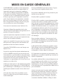
GENERAL WARNINGS
DO NOT use this product or any available optional
equipment without rst completely reading and under-
standing these instructions and any additional in-
structional material such as owner’s manuals, service
manuals or instruction sheets supplied with this prod-
uct or optional equipment. If you are unable to under-
stand the warnings, cautions or instructions, contact a
healthcare professional, dealer or technical personnel
before attempting to use this equipment - otherwise,
injury or damage may occur.
Read all the instructions before using the bed.
Refer to the owner’s manuals for beds and rails for ad-
ditional product and safety information.
After any adjustments, repair or service and before
use, make sure all attaching hardware is tightened
securely.
After the bed has been assembled, always test to make
sure that all sections of the bed are properly and se-
curely in place before using.
ALWAYS use caster locks except when moving the
bed.
Body weight should be evenly distributed over the
surface of the bed. DO NOT lay, sit or lean in such
a way that your entire body weight is placed only on
raised head or foot sections of the bed. This includes
when assisting the user in repositioning or transferring
in or out of bed.
Check all parts for shipping damage and test before
using. In case of damage, DO NOT use. Contact a
qualied technician for further instruction.
Close supervision is necessary when this bed is used
by or near children or people with disabilities.
DO NOT let any individual underneath the bed or in
between the raised bed frame components at anytime.
DO NOT permit more than one person on/in the bed at
any time.
DO NOT use outdoors.
DO NOT use this product or any available optional
equipment without rst completely reading and under-
standing these instructions and any additional in-
structional material such as owner’s manuals, service
manuals or instruction sheets supplied with this prod-
uct or optional equipment. If you are unable to under-
stand the warnings, cautions or instructions, contact a
healthcare professional, dealer or technical personnel
before attempting to use this equipment - otherwise,
injury or damage may occur.
For Dealers Only - Set-up and Assembly Instructions
are in the rear of this manual.These procedures must
be performed by a qualied technicians only.
The March 2006 version of the FDA’s bed safety
guidelines are published by Hospital Bed Safety
Workgroup. The latest revision of this document is
available at http://www.fda.gov.
If the unit is not working properly, call a qualied
technician to examine the unit and repair it.
Drive Medical products are specically designed
and manufactured for use in conjunction with Drive
Medical accessories. Accessories designed by other
manufacturers have not been tested by Drive Medical
and are not recommended for use with Drive Medical
products.
Keep all moving parts, including the main frame,
mattress deck (head and foot springs/sections) and all
drive shafts free of obstruction (i.e. blankets/sheets,
heating blankets/pads, tubing, wiring, etc. and other
types of products using electric cords which may get
tangled around the bed, side rails or legs) during op-
eration of the bed.
Keep the product a minimum of 12 inches away from
any direct heat source.
Make sure head and foot springs/sections are connect-
ed securely to the universal bed ends before use.
Physically challenged individuals who cannot prevent
themselves from rolling/climbing out of the this bed

may require alternative safe means of restraint.
Procedures other than those described in this manual
must be performed by a qualied technician.
Risk of injury to persons - DO NOT place video
equipment such as televisions or computer monitors
on bed.
NEVER allow patients to use trapeze or traction units
as a total individual weight support.
Trapeze units are to be used only for assisting the pa-
tient in repositioning or transferring into or out of bed.
Trapeze units must be positioned on a universal bed
end as near as possible to the center point of the bed
end.
The bed is not designed to be used as a patient trans-
port. When transporting a patient, use an approved
patient transport. Otherwise, injury or damage may
result.
The bed may be equipped with locking casters. When
transferring into or out of the bed, always lock the
locking caster(s). Inspect for correct locking action
on caster locks before using bed. Even with casters
properly locked, some ooring surfaces such as tile or
wood, will allow the bed to move under some condi-
tions. Use on surfaces such as these must be evaluated
by the care provider.
The initial set up of this bed must be performed by a
qualied technician.
The total weight limit of the Drive Medical 42-inch
(106.7 cm) wide Bariatric bed (including accessories,
mattress, occupant and any other person/object po-
sitioned on the bed) is 650 pounds (294.4 kg.); 520
pounds (235.9 kg) patient weight.
Use this bed only for its intended use as described in
these instructions. DO NOT use attachments not rec-
ommended by the manufacturer.
After raising/lowering the head/foot end of the bed,
check the distance between the bottom of the bed rail
and the mattress. If there is excessive distance between
the bottom of the bed rail and the mattress in which
individuals may become entangled, adjust the height
of the bed rail (if applicable), or provide alternative
means of patient protection.
Once patient assessment concludes that the patient’s
condition increases the chance of entrapment, the bed
MUST be in the at position when left unattended.
Proper patient assessment and monitoring, and proper
maintenance and use of equipment is required to
reduce the risk of entrapment. Variations in bed rail
dimensions, and mattress thickness, size or density
could increase the risk of entrapment. Visit the FDA
website at http://www.fda.gov to learn about the risks
of entrapment.
Replacement mattresses and bed side rails with dimen-
sions different than the original equipment supplied or
specied by the bed frame manufacturer are not inter-
changeable. Variations in bed side rail design, width
and thickness or rmness of the mattress could cause/
contribute to entrapment. Use only authorized Drive
Medical replacement parts and/or accessories other-
wise the warranty is void. Drive Medical will not be
responsible for any damage or injury that may result.
To reduce the risk of entrapment make certain that the
bed rail cross braces DO NOT exceed the width of the
mattress. Mattress MUST t bed frame and side rails
snugly to reduce the risk of entrapment.
When operating this bed, ALWAYS ensure that the in-
dividual utilizing the bed is positioned properly within
the connes of the bed. DO NOT let any extremities
protrude over the side or between the bed rails when
performing these functions.
Drive Medical recommends that the mattress be cen-
tered on the bed frame. Otherwise, individuals may
become entangled between the bed rail and the bed
frame.
Mattress MUST t bed frame and assist rails snugly to
reduce the risk of entrapment.
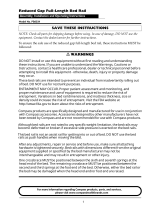
SAVE THESE INSTRUCTIONS
NOTE: Updated versions of this manual are available
on www.Drive Medical.com.

BED RAIL WARNINGS
Assist rails with dimensions different from the original
equipment supplied or specied by the bed manufac-
turer may not be interchangeable and may result in
entrapment or other injury.
Although bed rails are not rated to any specic weight
limitation, the bed rails may become deformed or
broken if excessive side pressure is exerted on the bed
rails. The bed rail is not an assist rail for getting into or
out of bed. DO NOT use the bed rails as push handles
when moving the bed.
Always test to make sure that the side rails are prop-
erly and securely in place before using the bed.
DO NOT install the optional bed rails without reading
and understanding all of the instructions in the instruc-
tion sheet that accompanies the bed rail kit.
DO NOT use the side rails as push handles for moving
the bed.
These bed rails are intended to prevent an individual
from inadvertently rolling out of bed. DO NOT use for
restraint purposes.
When used with a manual/electrical bed, the bed rails
DO NOT fall under any weight limitations. Bed rails
can be deformed or broken if excessive side pressure
is exerted on the bed rails. These bed rails are used for
the purpose of preventing an individual from inad-
vertently rolling out of bed. The bed rails are NOT
intended nor may be used for restraint purposes. If
an individual is capable of injuring himself/herself, a
physician or a healthcare professional should be con-
sulted for alternative means of safe restraint.
ELECTRICAL WARNINGS
A safety feature of this product includes protection
against overheating caused by excessive or extended
periods of operation. Depending on the duration, this
includes multiple or repeated adjustments or the use
of multiple functions at one time. To ensure trouble
free operation, always allow a slight pause between
multiple adjustments and avoid pressing more than
one function button at a time. If thermal protection
activation should occur, the bed will not respond to
pendant commands. Given this situation, release the
pendant button and allow the bed unit to sit for several
minutes. This will allow the protection function time
to reset and restore bed function. Depending on sever-
ity of the initial overheating, this could take up to 30
minutes.
Allow a slight pause between adjustments and avoid
pressing multiple buttons at the same time. If pendant
buttons are depressed too rapidly or multiple buttons
are pressed at the same time, the desired feature may
not activate. Simply release the pendant button, permit
a slight pause and then activate the next operation.
ALWAYS remove manual crank(s) before performing
electronic functions. Otherwise, the crank(s) will turn
when the motor is on and could cause personal injury
or damage to the bed.
Always unplug the bed from the electrical outlet be-
fore cleaning.
DO NOT open assemblies such as the motors, pen-
dant, junction boxes or gear boxes. No user service-
able parts are inside. Only qualied technicians are
permitted to repair these parts. If unqualied individu-
als perform any work on these beds, the warranty is
void.
DO NOT place pendant under or between objects.
This may unintentionally press the buttons and may
cause injury or damage.
Electronic equipment may be inuenced by Radio
Frequency Interference (RFI). Caution should be
exercised with regard to the use of portable communi-
cations equipment in the area around such equipment.
If RFI causes erratic behavior, unplug the electric bed
IMMEDIATELY. Leave unplugged while transmission
is in progress.
Ensure all cables and cords are routed such that they
will not become entangled or pinched. Otherwise dam-
age or injury may result.
If a button on the pendant does not release or sticks,
the bed spring will not stop moving.
If a liquid is spilled in or around the electric bed,

unplug the electric bed before cleaning. Clean up the
spill and allow the electric bed or the area around the
electric bed to dry thoroughly before using the electric
controls again.
Inspect the covering of the bed’s control panel and the
patient control panel to assure that the covering is not
cracked or damaged.
Keep all electrical cords away from heated or hot
surfaces.
Keep the cord away from heated surfaces.
NEVER operate if the unit has a damaged cord or
plug. If it is not working properly, call a qualied tech-
nician for examination and repair.
NEVER operate this bed if it has a damaged cord
or plug, if it is not working properly, if it has been
dropped, damaged, or dropped into water. Return the
bed to a service center for examination and repair.
On Full Electric beds, the Hi/Lo crank MUST be
removed before the bed is used. Failure to remove the
crank may cause damage or personal injury.
Refer servicing to qualied personnel only. Ground-
ing reliability depends upon a properly grounded wall
outlet.
The pendant and power cords must be routed and
secured properly to ensure that the cords DO NOT be-
come entangled, pinched and/or severed during opera-
tion of the electric bed.
Unplug from the outlet before servicing.
Unplug the power cord from its power source before
performing any maintenance on the manual/electric
bed. DO NOT unplug the power cord from the junc-
tion box. Damage to cord will result.
Use caution when disconnecting the pendant. DO
NOT press pendant buttons.
When bed is not to be used for an extended period,
unplug electric bed from the wall outlet.
When using an extension cord, use only a three wire
extension cord having at least 16 AWG (American
Wire Gauge) wire and the same or higher electrical
rating as the device being connected. Use of improper
extension cord could result in a risk of re and elec-
tric shock. Three to two prong adapters should not be
used. Use of three prong adapters can result in improp-
er grounding and present a shock hazard to the user.
When using nasal or masked type oxygen administer-
ing equipment, the oxygen or air tubing MUST be
routed and secured properly to ensure that the tubing
does not become entangled and/or severed during nor-
mal operation of the bed.
DO NOT use near explosive gases.
Possible re hazard when used with oxygen adminis-
tering equipment other than nasal or masked type.
Use masked or nasal type oxygen administering equip-
ment only in conjunction with this bed. The use of
ANY other type of oxygen administering equipment
can result in a re hazard.
Before connecting/disconnecting the connections at
the junction box, make sure the cable lock is removed
by lightly depressing on the end tabs and lifting. After
connectors are plugged in, route all cables into the
cable lock slots and snap the cable lock in place. When
installing any connectors into the junction box, be sure
the cable lock is secure after installation - otherwise,
injury or damage may occur.
DO NOT force the connector into the junction box,
otherwise - injury or damage may occur.
DO NOT unplug power cord from junction box.
DO NOT unplug power cord from motor housing.

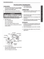
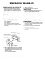
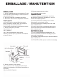
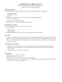
DESEMPACANDO EL PRODUCTO
1. Verique que los componentes o la caja de la
cama no estén dañados. Si detecta daños, pón
gase en contacto con su distribuidor local DRIVE.
2. Retire cualquier empaque suelto de las cajas.
3. Saque cuidadosamente todos los componentes
de las cajas.
PRECAUCIÓN
NO trate de activar los controles de la cama antes
de terminar el montaje ya que esto puede dañar los
componentes de la cama.
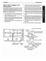
El contenido de las tres cajas es el siguiente:
1. Caja de los EXTREMOS DE LA CAMA:
Una (1) CABECERA.
Una (1) PIECERA.
Un (1) montaje de eje impulsor, dos piezas.
Cuatro (4) ruedas (dos (2) con candado y dos (2)
sin candado).
EMPAQUE/ MANEJO
Bolsa de plástico
Cabecera
Piecera
Caja de
embalaje
Ruedas
Bolsa de plástico
Material de embalaje
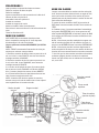
2. Caja del TAMBOR DE RESORTE DE LA PIECERA:
Un (1) TAMBOR DE RESORTE DE LA PIECERA
(camas eléctricas incluyen control remoto, caja de
conexiones y cable).
Una (1) manivela de emergencia.
3. Caja de la CABECERA:
Un (1) tambor de resortes de la cabecera.
INSPECCIÓN
1. Examine cuidadosamente cada artículo para veri
car que no existan ralladuras, hendiduras,
dobleces o cualquier otro tipo de daño.
2. Inspeccione el cable de fuente de energía para
vericar que el cable y/o enchufe no estén dañados.
3. Inspeccione la caja de conexiones para vericar que
los conectores no estén dañados.
4. Asegúrese que los enchufes del motor estén en
buenas condiciones de trabajo y que encajen
adecuadamente dentro de la caja de conexiones.
ALMACENAJE
1. Si no va a armar la cama inmediatamente, conserve
las cajas y el empaque durante el almacenaje hasta
que realice el montaje.
2. Almacene la cama bariátrica completamente
empacada en un área seca.
3. NO coloque otros objetos sobre las cajas
empacadas.
Tambor de resortes
de la piecera
Caja de embalaje
Material de embalaje
No se muestra en la gura:
Caja de conexiones con cable
Control remoto
Mango de manivela de emergencia
Caja de embalaje
Material de
embalaje
Tambor de resortes
de la cabecera
Tela de
eslabones
Tela de
eslabones
(15300 sólo)

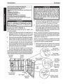
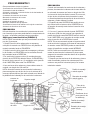
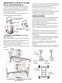
PROCEDIMIENTO 1
Extremo de
la piecera
Soporte central
Un (1) montaje
de motor
Tubo de
tiro
Extremo de
la cabecera
Ángulo de 130
o
Dos (2) montajes
de motor
Este procedimiento incluye lo siguiente:
Conectando las secciones de la cabecera/ piecera
Conectando la tela de eslabones
Ajustando y volviendo a conectar el tubo de tiro del tambor de
resortes de la cabecera
Levantando los extremos de la cama
Montando los extremos de la cama
Instalando las ruedas
Instalando el armazón de apoyo
Montaje e instalación del eje impulsor
Conectando el motor de la cabecera a la caja de conexiones
Activando las funciones de la cama
PRECAUCIÓN
NO trate de activar los controles de la cama antes de termi-
nar el montaje ya que esto puede dañar los componentes de
la cama o se pueden presentar lesiones personales.
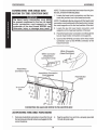
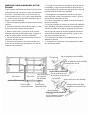
SOLO para cama bariátrica (FIGURA 2)
NOTA: DRIVE recomienda que este procedimiento se realice
por dos (2) personas.
1. Saque la sección de la cabecera de su empaque y
colóquelo de costado a su DERECHA con los pestillos de
montaje centrales hacia su IZQUIERDA.
2. Saque la sección de la piecera de su empaque y colóque-
lo de costado a su IZQUIERDA con los remaches de mon-
taje centrales hacia su DERECHA.
3. La sección de la cama con dos (2) montajes de motor
(sección de la PIECERA) debe de estar a su IZQUIERDA y
la sección de la cama con un (1) montaje de motor (sección
de la CABECERA) debe estar a su DERECHA.
4. Las secciones de la cabecera y piecera deben estar de
costado a un ángulo de 130o entre sí.
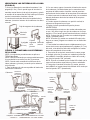
NOTA: Antes de conectar las secciones de la cabecera y
piecera asegúrese que el tubo de tiro en el extremo de la
cama que apunta hacia el piso esté colocado en el lateral de
la plataforma de la bandeja en la sección de la cabecera.
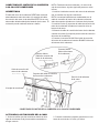
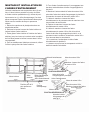
PRECAUCIÓN
Cuando esté montando las secciones de la cabecera y
piecera, el extremo de la cabecera de la cama debe es-
tar colocado de manera que forme un ángulo de 130o
con la sección de la piecera de la cama. De no ser así,
el tubo de tiro del extremo de la piecera de la cama
no librará la plataforma de soporte de la sección de la
cabecera y puede dañarse la unidad.
5. Enganche la parte SUPERIOR del pestillo de mon-
taje central sobre el extremo de la CABECERA con
el remache de montaje central sobre la sección de la
PIECERA.
6. Con una (1) persona uniendo la parte SUPERIOR
de la cama, pida a la otra persona que enganche el
pestillo de montaje central INFERIOR sobre la sección
de la CABECERA con el remache de montaje central
sobre la sección de la PIECERA de la cama.
NOTA: Tal vez sea necesario sujetar el soporte central
de la sección de la piecera de la cama de manera que
el remache central INFERIOR pueda ser maniobrado
dentro del pestillo de montaje central INFERIOR.
NOTA: Puede ser necesario tener que levantar leve-
mente las secciones de la cabecera O piecera para
asegurar los remaches centrales dentro de los pestillos
de montaje centrales.
7. Después que las secciones de la cabecera y piecera
estén conectadas, presione los extremos para colo-
carlos en una posición horizontal (recta) con la cama
todavía de costado.
Pestillo de montaje
central superior
Remache de montaje
central superior
Tubo de tiro
(sección de la
piecera)
Plataforma de so-
porte (sección de
la cabecera)
Pestillo de montaje
central inferior
Remache de montaje
central inferior

Drive
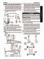
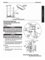
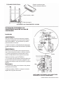
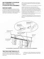
LEVANTANDO LOS EXTREMOS DE LA CAMA
(FIGURA 5)
1. Ahora, las patas de la cama deben levantarse ¼ de
pulgada (0.6 cm). Esto lo puede lograr al introducir la
manivela manual dentro de la caja de engranes y girarla
en sentido de las manecillas del reloj hasta que los extre-
mos de la cama estén a la altura correcta.
2. Introduzca la manivela dentro del receptáculo de la
cabecera y levante el extremo de la cabecera a la altura
correcta.
Caja de engranes de la cabecera
Manivela
manual
¼ pulgada
(0.6 cm)
Caja de
engranes
de la
piecera
Manivela
manual
FIGURA 5 - LEVANTANDO LOS EXTREMOS
DE LA CAMA
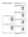
NOTA: Los siguientes procedimientos se aplican a
TODAS las camas.
NOTA: DRIVE recomienda que este procedimiento para
la cama bariátrica se realice por dos (2) personas.
NOTA: Cuando esté conectando los extremos de la
cama (cabecera y piecera), recuerde que la cabecera
es la más alta.
1. Pare la cabecera lo más cerca posible del tambor de
resortes de la cabecera.
Drive
Cabecera
Remaches
(Placas de
las equinas)
Trabas de
las esquinas
(cabecera)
Armazón del tambor de
resorte de la cabecera
EXTREMO DE LA CABECERA
Remaches
(Placas de
las esquinas)
Piecera
Armazón del tambor de
resortes de la piecera
Trabas
en las
esquinas
(piecera)
SECCIÓN DE LA PIECERA
FIGURA 6 – ENSAMBLANDO LOS EXTREMOS DE LA CAMA
2. Con una mano, agarre el armazón del tambor de resorte
de la cabecera y levántelo hasta que los remaches en las
esquinas del tambor estén a la altura correcta para intro-
ducirse dentro de las trabas de las esquinas de la cabecera.
3. Incline levemente la cabecera hacia atrás y los remaches
deberán deslizarse dentro de las trabas de las esquinas
más fácilmente.
4. Cuando regrese la cabecera a su posición vertical, la
cabecera se asegurará en su lugar.
5. Repita el mismo procedimiento para la piecera.
ADVERTENCIA
La cama bariátrica cuenta con las ruedas adecuadas para
su uso. NO utilice ningún otro tipo de ruedas con la cama
bariátrica. El no hacerlo puede ocasionar lesiones o daños.
NOTA: Coloque las dos (2) ruedas con candado diagonal-
mente y opuestas entre sí.
NOTA: Si las dos (2) ruedas con candado NO están inclu-
idas con su cama, póngase en contacto con un distribuidor
calicado.
1. Para instalar las ruedas levante cuidadosamente los ex-
tremos de la cama, aproximadamente 5 pulgadas (12.7 cm)
del suelo, e introduzca la echa del montaje de las ruedas
dentro del receptáculo de las ruedas.
2. Para evitar el movimiento excesivo de la cama, ponga
el candado a las dos (2) ruedas con candado al presionar
hacia ABAJO el candado ubicado en el lado de la rueda y
que tiene la leyenda "ON” (activado).
NOTA: El poner el candado en las ruedas NO evitará que la
cama se mueva sobre supercies muy lisas o resbalosas.
3. Para quitar el candado de las dos (2) ruedas, presione
hacia ABAJO en la parte lateral del candado de la rueda que
tiene la leyenda “OFF” (desactivado).
Rueda con
candado
Presione
AQUÍ para
activar
candado
Presione
AQUÍ para
desactivar
Rueda con
candado
Rueda con
candado

MONTAJE E INSTALACIÓN DEL EJE IM-
PULSOR
El eje impulsor está compuesto de dos (2) secciones.
La echa interna la cual tiene un botón de colocación
de resorte; y la echa externa, la cual tiene dos (2)
oricios para posición y un (1) oricio para almacena-
je. Juntas forman el eje impulsor telescópico que se
utiliza en camas bariátricas.
1. Retire las tapas de plástico de cada extremo del eje
impulsor.
2. Presione el botón de resorte del eje interior e intro-
duzca el eje interior dentro del eje exterior.
3. Deslice el eje interior y colóquelo en la posición
deseada dependiendo del tipo de cama y asegure el
botón de resorte dentro del oricio adecuado.
4. Coloque el botón de resorte dentro del oricio de
colocación del eje exterior.
5. Conecte el eje impulsor a la cama uniendo cual-
quiera de los extremos del eje impulsor a la caja de
engranes de la cabecera.
6. Conecte el otro extremo a la salida de la echa del mo-
tor Alto/Bajo y luego conecte la salida de la echa de la
caja de engranes de la piecera al acoplador de resorte de
la salida de la echa del motor Alto/Bajo.
7. Desenganche el acoplador de resorte del eje impul-
sor al presionar contra el acoplador de resorte y girar en
sentido de las manecillas del reloj.
8. Localice el acoplador de resorte de la echa de salida
del motor Alto/Bajo.
9. Libere el acoplador de resorte de la echa de salida del
motor Alto/Bajo para poder conectarlo correctamente con
la echa de salida de la caja de engranes de la piecera;
esto se logra al presionar contra el acoplador de resorte
de la echa de salida del motor Alto/Bajo y girar en sen-
tido de las manecillas del reloj.
10. El acoplador se liberará y se enganchará al eje de
salida de la piecera.
11. Asegúrese que todos los componentes estén instala-
dos de manera segura.
Eje interior
Eje exterior
Caja de engranes
de la piecera
Eje de salida
Posición para
almacenamiento
Posición para
camas bariátricas
Eje de salida de motor Alto/Bajo
Eje de salida de motor Alto/Bajo
Acoplador de resorte
Eje impulsor
Motor Alto/Bajo
POSICIÓN BLOQUEADA
Eje de salida de la caja
de engranes de la piecera
Eje impulsor
Eje de salida de motor Alto/Bajo
Salida del motor Alto/Bajo
Acoplador de resorte del eje
Eje de salida de la caja de
engranes de la piecera
Motor Alto/Bajo
POSICIÓN SIN BLOQUEAR

NOTA: Para desconectar la cabecera y el motor de la
caja de conexiones, siga los siguientes pasos en orden
inverso.
1. Localice el cable de conexión del motor de la cabecera
que se conecta a la caja de conexiones.
NOTA: Las camas bariátricas son embarcadas con el
cable de conexión del motor de la cabecera colocado
sobre los soportes ubicados en el extremo de la piecera.
2. Localice los dos (2) soportes del cable de conexión del
motor de la cabecera ubicados en la sección de la ca-
becera de la cama.
3. Alimente el cable de conexión del motor de la cabecera
a través de los dos (2) soportes para el cable de conexión
del motor de la cabecera.
4. Conecte el conector BLANCO del cable de conexión
del motor de la cabecera al conector BLANCO del motor
del extremo de la cabecera.
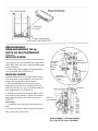
CONECTANDO EL MOTOR DE LA CABECERA
A LA CAJA DE CONEXIONES
ADVERTENCIA
El cable del motor de la cabecera DEBE estar colocado
adecuadamente sobre los cuatro (4) soportes del cable
de conexión del motor de la cabecera ANTES de su uso;
estos están ubicados debajo del armazón de la cama. El
no hacerlo puede ocasionar lesiones o daños.
Conector blanco
(Cable de conexión del
motor de la cabecera)
Conector blanco
(Motor del extremo
de la cabecera)
Cable de conexión del
motor de la cabecera
Soportes del cable de conexión
del motor de la cabecera
Sección de la cabecera
de la cama
A la caja de conexiones
CONECTANDO EL MOTOR DE LA CABECERA A LA CAJA DE CONEXIONES
2. Conecte el cable de la caja de conexiones en una
toma de corriente de 110 volts y 60 ciclos.
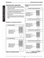
ACTIVANDO LAS FUNCIONES DE LA CAMA
1. Vuelva a vericar que las conexiones eléctricas de la
caja de conexiones de la piecera estén conectadas en
el lugar correcto.

TOTALMENTE ELÉCTRICA
Caja de conexiones para
modelo totalmente eléctrico
Control remoto y cable
Cable de energía
ACTIVANDO LAS FUNCIONES DE LA CAMA
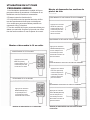
INSTALANDO/ RETIRANDO LOS
CONECTORES HACIA/DE LA CAJA DE
CONEXIONES
Instalando
ADVERTENCIA
Antes de instalar el conector dentro de la caja de
conexiones, asegúrese que la palanca de bloqueo
este HACIA ABAJO – de otra manera se pueden
presentar daños o lesiones.
1. Sujete el conector y colóquelo de tal manera que
la palanca de bloqueo esta HACIA ABAJO (FIGURA
1).
ADVERTENCIA
NO forcé el conector dentro de la caja de conexio-
nes, de hacerlo puede resultar en lesiones o daños.
2. Presione gentilmente el conector dentro de la
ranura correspondiente de la caja de conexiones
hasta que escuche un 'clic' (FIGURA 1).
3. Si el conector NO SE desliza fácilmente dentro de
la ranura de la caja de conexiones, asegúrese que
la palanca de bloqueo esté HACIA ABAJO y repita el
PASO 2.
Retirándolo
1. Presione hacia abajo en el extremo de la palanca
de bloqueo del conector.
2. Mientras realiza el PASO 1, coloque el conector
alejado de la caja de conexiones.
Conectores
Caja de
conexiones
Presione
hacia abajo
aquí para
retirarlo
Rueda
PARTE DE ABAJO DEL
EXTREMO DE LA PIECERA
INSTALANDO/ RETIRANDO LOS CONECTORES
HACIA/DE LA CAJA DE CONEXIONES

OPERACIÓN DE LA CAMA BARIÁTRICA
Levantando y bajando toda la cama
PARA LEVANTAR TODA LA CAMA
PARA BAJAR TODA LA CAMA
LEVANTANDO Y BAJANDO TODA LA CAMA
Levantando y bajando las secciones de
la cabecera y piecera.
PARA LEVANTAR LA SECCIÓN DEL TAMBOR
DE RESORTES DE LA CABECERA
PARA BAJAR LA SECCIÓN DEL TAMBOR DE
RESORTES DE LA CABECERA
PARA LEVANTAR LA SECCIÓN DEL TAMBOR
DE RESORTES DE LA PIECERA
PARA BAJAR LA SECCIÓN DEL TAMBOR DE
RESORTES DE LA PIECERA
LEVANTANDO Y BAJANDO LAS SECCIONES DE
LA CABECERA Y PIECERA
La page est en cours de chargement...
La page est en cours de chargement...
La page est en cours de chargement...
La page est en cours de chargement...
La page est en cours de chargement...
La page est en cours de chargement...
La page est en cours de chargement...
La page est en cours de chargement...
La page est en cours de chargement...
La page est en cours de chargement...
La page est en cours de chargement...
La page est en cours de chargement...
La page est en cours de chargement...
La page est en cours de chargement...
La page est en cours de chargement...
La page est en cours de chargement...
La page est en cours de chargement...
La page est en cours de chargement...
La page est en cours de chargement...
La page est en cours de chargement...
-
 1
1
-
 2
2
-
 3
3
-
 4
4
-
 5
5
-
 6
6
-
 7
7
-
 8
8
-
 9
9
-
 10
10
-
 11
11
-
 12
12
-
 13
13
-
 14
14
-
 15
15
-
 16
16
-
 17
17
-
 18
18
-
 19
19
-
 20
20
-
 21
21
-
 22
22
-
 23
23
-
 24
24
-
 25
25
-
 26
26
-
 27
27
-
 28
28
-
 29
29
-
 30
30
-
 31
31
-
 32
32
-
 33
33
-
 34
34
-
 35
35
-
 36
36
-
 37
37
-
 38
38
-
 39
39
-
 40
40


Drive Medical Full-Electric Bariatric Bed 42" Le manuel du propriétaire
- Taper
- Le manuel du propriétaire
dans d''autres langues
Documents connexes
Autres documents
-
Drive Medical Design 15302 Manuel utilisateur
-
Drive Medical Design 15004 Manuel utilisateur
-
 Kolcraft KF006 Product Instruction
-
 Mira Studios RF003 Product Instruction
-
 Kolcraft KF005 Product Instruction
-
Invacare IVC BAR6640IVC Assembly, Installation And Operating Instructions
-
 COMPASS HEALTH PB6034 Reduced Gap Full-Length Bed Rail Manuel utilisateur
-
Sunrise Medical IC-7714 Manuel utilisateur
-
-


