
ANALOG WAY® OCTO range EDITION : 04 / 05
User’s Manual
Manuel Utilisateur
OCTO-PLUS
™
OCTO-LOGO
™
OCTO-FADE
™
OCTO-FX
™
Models: OCP802, OLG802, OFD802, OFX802
TABLE OF CONTENTS
SAFETY INSTRUCTIONS...........................................................................................................................................................2
Chapter 1 : INTRODUCTION.......................................................................................................................................................5
Chapter 2 : STARTING .................................................................................................................................................................8
Chapter 3 : OPERATING MODE................................................................................................................................................12
Chapter 4 : USING FRAME STORE AND LOGO INSERTION ...............................................................................................15
Chapter 5 : LCD SCREEN DESCRIPTION................................................................................................................................17
Chapter 6 : LCD FUNCTIONS DESCRIPTION.........................................................................................................................20
Chapter 7 : UPDATING THE DEVICE ......................................................................................................................................28
Chapter 8 : CONTROL SOFTWARE..........................................................................................................................................29
Chapter 9 : REMOTE CONTROL PROGRAMMER'S GUIDE..................................................................................................33
Chapter 10 : OPTIONAL ACCESSORY: THE REMOTE KEYPAD (RK802-F)......................................................................40
Chapter 11 : TECHNICAL SPECIFICATIONS..........................................................................................................................41
WARRANTY...............................................................................................................................................................................84
TABLE DES MATIÈRES
INSTRUCTIONS DE SÉCURITÉ.................................................................................................................................................3
Chapitre 1 : INTRODUCTION....................................................................................................................................................45
Chapitre 2 : MISE EN SERVICE.................................................................................................................................................48
Chapitre 3 : MODE OPÉRATOIRE.............................................................................................................................................52
Chapitre 4 : UTILISATION DU FRAME STORE ET DE L'INCRUSTATION DE LOGO ......................................................55
Chapitre 5 : DESCRIPTION DE L'ÉCRAN LCD .......................................................................................................................57
Chapitre 6 : DESCRIPTION DES FONCTIONS DE L'ÉCRAN LCD........................................................................................60
Chapitre 7 : MISE A JOUR DU PRODUIT.................................................................................................................................68
Chapitre 8 : LOGICIEL DE CONTRÔLE ...................................................................................................................................69
Chapitre 9 : GUIDE DE PROGRAMMATION DE TÉLÉCOMMANDE ..................................................................................73
Chapitre 10 : ACCESSOIRE OPTIONNEL : LE REMOTE KEYPAD (RK802-F) ...................................................................80
Chapitre 11 : SPÉCIFICATIONS TECHNIQUES ......................................................................................................................81
GARANTIE .................................................................................................................................................................................84

OCTO range
PAGE 2
ENGLISH
SAFETY INSTRUCTIONS
All of the safety and operating instructions should be read before the product is operated and should be retained for further
reference. Please follow all of the warnings on this product and its operating instructions.
CAUTION
:
WARNING: To prevent the risk of electric shock and fire, do not expose this device to rain, humidity or intense
heat sources (such as heaters or direct sunlight). Slots and openings in the device are provided for
ventilation and to avoid overheating. Make sure the device is never placed on or near a textile
surface that could block the openings. Also keep away from excessive dust, vibrations and shocks.
POWER: Only use the power supply indicated on the device or on the power source. Devices equipped with a
grounding plug should only be used with a grounding type outlet. In no way should this grounding
be modified, avoided or suppressed.
POWER CORD: Use the On (I) / Off (O) switch to power On or Off devices equipped with that switch. All other
devices should be plugged and unplugged from wall outlet. In both cases, please follow these
instructions:
- The power cord of the device should be unplugged from the outlet when left unused for several
days.
- To unplug the device, do not pull on the power cord but always on the plug itself.
- The outlet should always be near the device and easily accessible.
- Power supply cords should be routed so that they are not likely to be walked on or pinched by
items placed upon or against them.
If the power supply cord is damaged, unplug the device. Using the device with a damaged power
supply cord may expose you to electric shocks or other hazards. Verify the condition of the power
supply cords once in a while. Contact your dealer or service center for replacement if damaged.
CONNECTIONS: All inputs and outputs (except for the power input) are TBTS defined under EN60950.
SERVICING: Do not attempt to service this product yourself by opening or removing covers and screws since it
may expose you to electric shocks or other hazards. Refer all problems to qualified service
personnel.
OPENINGS: Never push objects of any kind into this product through the openings. If liquids have been spilled or
objects have fallen into the device, unplug it immediately and have it checked by a qualified
technician.

OCTO range
PAGE 3
FRAN
Ç
AIS ITALIANO
INSTRUCTIONS DE SÉCURITÉ
Afin de mieux comprendre le fonctionnement de cet appareil nous vous conseillons de bien lire toutes les consignes de sécurité et de fonctionnement de
l’appareil avant utilisation. Conserver les instructions de sécurité et de fonctionnement afin de pouvoir les consulter ultérieurement. Respecter toutes les
consignes marquées dans la documentation, sur le produit et sur ce document.
ATTENTION : Afin de prévenir tout risque de choc électrique et d’incendie, ne pas exposer cet appareil à la pluie, à l’humidité et aux sources de chaleur
intense.
INSTALLATION : Veillez à assurer une circulation d’air suffisante pour éviter toute surchauffe à l’intérieur de l’appareil. Ne placez pas l’appareil sur ou
proximité de surface textile susceptible d’obstruer les orifices de ventilation. N’installez pas l’appareil à proximité de sources de chaleur comme un radiateur
ou une bouche d’air chaud, ni dans un endroit exposé au rayonnement solaire direct, à des poussières excessives, à des vibrations ou à des chocs mécaniques.
Ceci pourrait provoquer un mauvais fonctionnement et un accident.
ALIMENTATION : Ne faire fonctionner l’appareil qu’avec la source d’alimentation indiquée sur l’appareil ou sur son bloc alimentation. Pour les appareils
équipés d’une alimentation principale avec fil de terre, ils doivent être obligatoirement connectés sur une source équipée d’une mise à la terre efficace. En
aucun cas cette liaison de terre ne devra être modifiée, contournée ou supprimée.
CORDON D’ALIMENTATION : Pour les appareils équipés d’un interrupteur général (Marche I / Arrêt O), la mise sous tension et la mise hors tension se fait
en actionnant cet interrupteur général. Pour les appareils sans interrupteur général, la mise sous tension et la mise hors tension se fait directement en
connectant et déconnectant le cordon d'alimentation de la prise murale.
Dans les 2 cas ci-dessus appliquer les consignes suivantes :
- Débrancher le cordon d'alimentation de la prise murale si vous prévoyez de ne pas utiliser l'appareil pendant quelques jours ou plus.
- Pour débrancher le cordon, tirez le par la fiche. Ne tirez jamais sur le cordon proprement dit.
- La prise d’alimentation doit se trouver à proximité de l’appareil et être aisément accessible.
- Ne laissez pas tomber le cordon d’alimentation et ne posez pas d’objets lourds dessus.
Si le cordon d’alimentation est endommagé, débranchez le immédiatement de la prise murale. Il est dangereux de faire fonctionner cet appareil avec un cordon
endommagé, un câble abîmé peut provoquer un risque d’incendie ou un choc électrique. Vérifier le câble d’alimentation de temps en temps. Contacter votre
revendeur ou le service après vente pour un remplacement.
CONNEXIONS : Toutes les entrées et sorties (exceptée l’entrée secteur) sont de type TBTS (Très Basse Tension de Sécurité) définies selon EN 60950.
RÉPARATION ET MAINTENANCE : L’utilisateur ne doit en aucun cas essayer de procéder aux opérations de dépannage, car l’ouverture des appareils par
retrait des capots ou de toutes autres pièces constituant les boîtiers ainsi que le dévissage des vis apparentes à l’extérieur, risque d’exposer l’utilisateur à des
chocs électriques ou autres dangers. Contacter le service après vente ou votre revendeur ou s’adresser à un personnel qualifié uniquement.
OUVERTURES ET ORIFICES : Les appareils peuvent comporter des ouvertures (aération, fentes, etc...), veuillez ne jamais y introduire d’objets et ne jamais
obstruer ses ouvertures. Si un liquide ou un objet pénètre à l’intérieur de l’appareil, débranchez immédiatement l’appareil et faites le contrôler par un personnel
qualifié avant de le remettre en service.
ISTRUZIONI DI SICUREZZA
Allo scopo di capire meglio il funzionamento di questa apparecchiatura vi consigliamo di leggere bene tutti i consigli di sicurezza e di funzionamento prima
dell’utilizzo. Conservare le istruzioni di sicurezza e di funzionamento al fine di poterle consultare ulteriormente. Seguire tutti i consigli indicati su questo
manuale e sull’apparecchiatura.
ATTENZIONE : Al fine di prevenire qualsiasi rischio di shock elettrico e d’incendio, non esporre l’apparecchiatura a pioggia, umidità e a sorgenti di
eccessivo calore.
INSTALLAZIONE : Assicuratevi che vi sia una sufficiente circolazione d’aria per evitare qualsiasi surriscaldamento all’interno dell’apparecchiatura. Non
collocare l’apparecchiatura in prossimità o su superfici tessili suscettibili di ostruire il funzionamento della ventilazione. Non installate l’apparecchiatura in
prossimità di sorgenti di calore come un radiatore o una fuoruscita d’aria calda, né in un posto esposto direttamente ai raggi del sole, a polvere eccessiva, a
vibrazioni o a shock meccanici. Ció potrebbe provocare un erroneo funzionamento e un incidente.
ALIMENTAZIONE : Far funzionare l’apparecchiatura solo con la sorgente d’alimentazione indicata sull’apparecchiatura o sul suo alimentatore. Per le
apparecchiature fornite di un’alimentazione principale con cavo di terra, queste devono essere obbligatoriamente collegate su una sorgente fornita di una
efficiente messa a terra. In nessun caso questo collegamento potrà essere modificato, sostituito o eliminato.
CAVO DI ALIMENTAZIONE : Per le apparecchiature fornite di interruttore generale (Acceso I / Spento O), l’accensione e lo spegnimento
dell’apparecchiatura si effettuano attraverso l’interruttore. Per le apparecchiature senza interruttore generale, l’accensione e lo spegnimento si effettuano
direttamente inserendo o disinserendo la spina del cavo nella presa murale.
In entrambe i casi applicare i seguenti consigli :
- Disconnettere l’apparecchiatura dalla presa murale se si prevede di non utilizzarla per qualche giorno.
- Per disconnettere il cavo tirare facendo forza sul connettore.
- La presa d’alimentazione deve trovarsi in prossimità dell’apparecchiatura ed essere facilmente accessibile.
- Non far cadere il cavo di alimentazione né appoggiarci sopra degli oggetti pesanti.
Se il cavo di alimentazione é danneggiato, spegnere immediatamente l’apparecchiatura. E’ pericoloso far funzionare questa apparecchiatura con un cavo di
alimentazione danneggiato, un cavo graffiato puó provocare un rischio di incendio o uno shock elettrico. Verificare il cavo di alimentazione spesso. Contattare
il vostro rivenditore o il servizio assistenza per una sostituzione.
CONNESSIONE : Tutti gli ingressi e le uscite (eccetto l’alimentazione) sono di tipo TBTS definite secondo EN 60950.
RIPARAZIONI E ASSISTENZA : L’utilizzatore non deve in nessun caso cercare di riparare l’apparecchiatura, poiché con l’apertura del coperchio metallico
o di qualsiasi altro pezzo costituente la scatola metallica, nonché svitare le viti che appaiono esteriormente, poiché ció puó provocare all’utilizzatore un
rischio di shock elettrico o altri rischi.
APERTURE DI VENTILAZIONE : Le apparecchiature possono comportare delle aperture di ventilazione, si prega di non introdurre mai oggetti o ostruire le
sue fessure. Se un liquido o un oggetto penetra all’interno dell’apparecchiatura, disconnetterla e farla controllare da personale qualificato prima di rimetterla in
servizio.

OCTO range
PAGE 4
ESPAÑOL DEUTSCH
SICHERHEITSHINWEISE
Um den Betrieb dieses Geräts zu verstehen, raten wir Ihnen vor der Inbetriebnahme alle Sicherheits- und Betriebsanweisungen genau zu lesen. Diese
Sicherheits- und Betriebsanweisungen für einen späteren Gebrauch sicher aufbewahren. Alle in den Unterlagen, an dem Gerät und hier angegebenen
Sicherheitsanweisungen einhalten.
VORSICHT & WARNUNG
ACHTUNG: um jegliches Risiko eines Stromschlags oder Feuers zu vermeiden, das Gerät nicht Regen, Feuchtigkeit oder intensiven Wärmequellen aussetzen.
EINBAU : Eine ausreichende Luftzufuhr sicherstellen, um jegliche Überhitzung im Gerät zu vermeiden. Das Gerät nicht auf und in Nähe von
Textiloberflächen, die Belüftungsöffnungen verschließen können, aufstellen. Das Gerät nicht in Nähe von Wärmequellen, wie z.B. Heizkörper oder
Warmluftkappe, aufstellen und es nicht dem direkten Sonnenlicht, übermäßigem Staub, Vibrationen oder mechanischen Stößen aussetzen. Dies kann zu
Betriebsstörungen und Unfällen führen.
STROMVERSORGUNG : Das Gerät nur mit der auf dem Gerät oder dem Netzteil angegebenen Netzspannung betreiben. Geräte mit geerdeter
Hauptstromversorgung müssen an eine Stromquelle mit effizienter Erdung angeschlossen werden. Diese Erdung darf auf keinen Fall geändert, umgangen oder
entfernt werden.
STROMKABEL : Für Geräte mit einem Hauptschalter (Ein/Aus) erfolgt die Stromversorgung und Unterbrechung mittels dieses Hauptschalters. Geräte ohne
Hauptschalter werden durch das Einstecken oder Herausziehen des Steckers in den Wandanschluß ein- oder ausgeschaltet. Für beide Fälle gelten folgende
Richtlinien :
- Den Stecker aus dem Wandanschluß herausziehen wenn Sie das Gerät mehrere Tage oder länger nicht benutzen.
- Das Kabel mittels dem Stecker herausziehen. Niemals am Stromkabel selbst ziehen.
- Die Steckdose muß sich in der Nähe des Geräts befinden und leicht zugänglich sein.
- Das Stromkabel nicht fallen lassen und keine schweren Gegenstände auf es stellen.
Wenn das Stromkabel beschädigt ist, das Gerät sofort abschalten. Es ist gefährlich das Gerät mit einem beschädigten Stromkabel zu betreiben; ein abgenutztes
Kabel kann zu einem Feuer oder Stromschlag führen. Das Stromkabel regelmäßig untersuchen. Für den Ersatz, wenden Sie sich an Ihren Verkäufer oder
Kundendienststelle.
ANSCHLÜSSE : Bei allen Ein- und Ausgängen (außer der Stromversorgung) handelt es sich, gemäß EN 60950, um Sicherheits- Kleinspannunganschlüsse.
REPARATUR UND WARTUNG : Der Benutzer darf keinesfalls versuchen das Gerät selbst zu reparieren, die Öffnung des Geräts durch Abnahme der
Abdeckhaube oder jeglichen anderen Teils des Gehäuses sowie die Entfernung von außen sichtbaren Schrauben zu Stromschlägen oder anderen Gefahren für
den Benutzer führen kann. Wenden Sie sich an Ihren Verkäufer, Ihre Kundendienststelle oder an qualifizierte Fachkräfte.
ÖFFNUNGEN UND MUNDUNGEN : Die Geräte können über Öffnungen verfügen (Belüftung, Schlitze, usw.). Niemals Gegenstände in die Öffnungen
einführen oder die Öffnungen verschließen. Wenn eine Flüssigkeit oder ein Gegenstand in das Gerät gelangt, den Stecker herausziehen und es vor einer neuen
Inbetriebnahme von qualifiziertem Fachpersonal überprüfen lassen.
INSTRUCCIONES DE SEGURIDAD
Para comprender mejor el funcionamiento de este aparato, le recomendamos que lea cuidadosamente todas las consignas de seguridad y de funcionamiento del
aparato antes de usarlo. Conserve las instrucciones de seguridad y de funcionamiento para que pueda consultarlas posteriormente. Respete todas las consignas
indicadas en la documentación, relacionadas con el producto y este documento.
PRECAUCIONES Y OBSERVACIONES
CUIDADO : Para prevenir cualquier riesgo de choque eléctrico y de incendio, no exponga este aparato a la lluvia, a la humedad ni a fuentes de calorintensas.
INSTALACIÓN : Cerciórese de que haya una circulación de aire suficiente para evitar cualquier sobrecalentamiento al interior del aparato. No coloque el
aparato cerca ni sobre una superficie textil que pudiera obstruir los orificios de ventilación. No instale el aparato cerca de fuentes de calor como radiador o
boca de aire caliente, ni en un lugar expuesto a los rayos solares directos o al polvo excesivo, a las vibraciones o a los choques mecánicos. Esto podría
provocar su mal funcionamiento o un accidente.
ALIMENTACIÓN : Ponga a funcionar el aparato únicamente con la fuente de alimentación que se indica en el aparato o en su bloque de alimentación. Los
aparatos equipados con una alimentación principal con hilo de tierra deben estar conectados obligatoriamente a una fuente equipada con una puesta a tierra
eficaz. Por ningún motivo este enlace de tierra deberá ser modificado, cambiado o suprimido.
CABLE DE ALIMENTACIÓN : Para los aparatos equipados con un interruptor general (Marcha I / Paro O), la puesta bajo tensión y la puesta fuera de tensión
se hace accionando este interruptor general.. En los aparatos que no tienen interruptor general, la puesta bajo tensión y la puesta fuera de tensión se hace
directamente conectando y desconectando el enchufe mural.
En ambos casos, se deberá respetar las siguientes consignas:
- Desconectar el aparato del enchufe mural si no piensa utilizarlo durante varios días.
- Para desconectar el cable, tire de la clavija. No tire nunca del cable propiamente dicho.
- El enchufe de alimentación debe estar cerca del aparato y ser de fácil acceso.
- No deje caer el cable de alimentación ni coloque objetos pesados encima de él.
Si el cable de alimentación sufriera algún daño, ponga el aparato inmediatamente fuera de tensión. Es peligroso hacer funcionar este aparato con un cable
averiado, ya que un cable dañado puede provocar un incendio o un choque eléctrico. Verifique el estado del cable de alimentación de vez en cuando. Póngase
en contacto con su distribuidor o con el servicio de posventa si necesita cambiarlo.
CONEXIONES : Todas las entradas y salidas (excepto la entrada del sector) son de tipo TBTS (Muy Baja Tensión de Seguridad) definidas según EN 60950.
REPARACIÓN Y MANTENIMIENTO : Por ningún motivo, el usuario deberá tratar de efectuar operaciones de reparación, ya que si abre los aparatos
retirando el capó o cualquier otra pieza que forma parte de las cajas o si destornilla los tornillos aparentes exteriores, existe el riesgo de producirse una
explosión, choques eléctricos o cualquier otro incidente. Contacte el servicio de posventa, a su distribuidor o dirigirse con personal cualificado únicamente.
ABERTURAS Y ORIFICIOS : Los aparatos pueden contener aberturas (aireación, ranuras, etc.). No introduzca allí ningún objeto ni obstruya nunca estas
aberturas. Si un líquido o un objeto penetra al interior del aparato, desconéctelo y hágalo revisar por personal cualificado antes de ponerlo nuevamente en
servicio.

OCTO range
PAGE 5
OCTO-PLUS
™
/ OCTO-LOGO
™
/ OCTO-FADE
™
/ OCTO-FX
™
Chapter 1 : INTRODUCTION
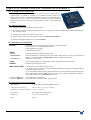
1-1. ACCESSORIES SUPPLIED WITH YOUR DEVICE
• 1 AC Power supply cord.
• 1 VGA cable (HD15 male / male connector).
• 1 S.VIDEO (Y/C) cable (4-pin mini DIN male / 2 BNC male connectors).
• 1 HD15 to BNC (x5) cable (male / male).
• 1 Set of 6 MCO (5-pin) female connectors (for audio connection).
• 2 white labels: to rename the input selection buttons (OLG802, OFD802, OFX802 only).
• 1 CD-ROM (Remote Control Software).
• 1 User’s Manual.
1-2. GENERAL INFORMATION
• The OCTO-PLUS
™
, is a computer & video up/down scaler switcher with 8 universal A/V inputs. Thus, any signal
(computer and video) can be displayed on any Data Display Device. The OCTO-PLUS
™
can be used in 2 switching
mode. The "Ultra Smooth" Switching mode, allows to switch between any sources (computer & video) with a fade
colored transition. The Seamless mode, allows to switch seamlessly between the "referenced" computer input and the
other inputs.
• The OCTO-LOGO
™
is a computer & video up/down scaler switcher featuring LOGO insertion and FRAME
Store functions, thanks to its large non-volatile memory. Fitted with 8 universal A/V inputs, it performs a fast and
ultra-smooth transition between any video & computer sources. It also allows a true seamless switching between one
computer input (direct) and any other video or computer inputs.
LOGO Insertion of a true Hi-Res.16 million colors image defined either by keying or image cut out by the user. The
LOGO can be positioned anywhere on the screen and distributed to any of the 8 inputs. FRAME STORE and LOGO
can be flash captured from any video or computer sources into a non-volatile memory.
• The OCTO-FADE
™
is a computer & video up/down scaler switcher featuring FADING & TITLING effects. Fitted
with 8 universal A/V inputs, it performs a fast and ultra-smooth transition between any video or computer sources. It
also allows a true seamless switching between a reference computer & computer or video inputs. The OCTO-FADE
™
provides High Performance capabilities and powerful functionalities.
TITLING EFFECTS: It is possible to maintain an active title while switching between two inputs. The title will
remain on the screen during the transition. Another feature is the shadow title with settable vertical position and size.
Moreover, the OCTO-FADE
™
allows displaying a title over computer & video images.
FADING EFFECTS: the product features Fade, Dissolve, Black & Cut effects between video (TV) and computer or
between computer & computer. The OCTO-FADE
™
also allows adjusting the cross-fading duration.
• The OCTO-FX
™
combines the function of both OCTO-FADE
™
and OCTO-LOGO
™
.
• The OCTO devices can fit with the native resolution of the display device and provide you with a high image quality
thanks to its integrated digital decoder, improved 3:2 and 2:2 pull down circuitry, auto-adaptive pixel by pixel 3D
motion compensation, Time Base Corrector, Frame Rate Converter & Follower and its 2 Buffered Outputs. All
individual image control settings are stored in non-volatile memories.
Each of the 8 Universal inputs is fitted with a balanced stereo audio line. The audio can either follow or break away
from the video image. One additional full featured field operational microphone input is provided with “anti-pop” filter,
Noise Gate and compressor function. These ultra compact devices are especially dedicated to High Resolution A/V
presentation displays, conference and boardrooms and events.
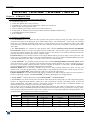
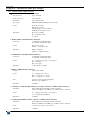
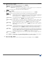
FEATURES
MODEL
Seamless transition.
Ultra smooth transition
(fade color).
Logo & Frame
insertion.
Fading & Titling.
OCTO-PLUS
•
•
OCTO-LOGO
•
•
•
OCTO-FADE
•
•
•
OCTO-FX
•
•
•
•

Chapter 1 : INTRODUCTION (continued) OCTO range
PAGE 6
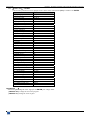
1-3. DEVICES & OPTIONS REFERENCES
REFERENCE DESIGNATION
OCP802 OCTO-PLUS
™
.
OLG802 OCTO-LOGO
™
.
OFD802 OCTO-FADE
™
.
OFX802 OCTO-FX
™
.
OPT-VOV802 Voice Over control for microphone (optional).
OPT-LAN LAN communication port (optional)
RK802-F Remote KEYPAD for controlling an OCTO device (optional).
10077 CABLE (HD15 M / HD15 M) L = 1.8 m
10023 CABLE (HD15 M / 5BNC M) L = 1.8 m
10102 CABLE (4-pin mini DIN M / 2BNC M) L = 1.8 m
10009 CABLE (4-pin mini DIN M / 4-pin mini DIN M) L = 1.2 m (optional).
10123 CABLE (HD15 M / 5BNC F) L = 0.5 m (optional).
10124 CABLE (4-pin mini DIN F / HD15 M) L = 0.2 m (optional).
1-4. INSTALLATION
IMPORTANT:
Please read all the safety instructions (pages 2 to 4) before starting.
• Table Top Mounting:
The OCTO can be used directly on a table: the unit is equipped with 4 plastic feet.
• Rack Mounting:
The OCTO is compatible with a 19" enclosure. To install the OCTO into a 19” rack: Attach the
OCTO to the rack by using 4 screws in the front panel holes (screws are not included).
IMPORTANT:
• The openings in the rear and side panels are for cooling. Do not cover these openings.
• Be sure that no weight is added to the OCTO in excess of 2 kg (4.4 lbs.).
• The maximum ambient operating temperature must not exceed 40°C (104°F).
• The rack and all mounted equipment in it must be reliably grounded to national and
local electrical codes.
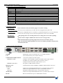
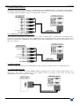
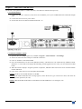
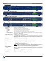
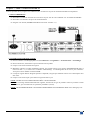
1-5. REAR PANEL DESCRIPTION
POWER: Standard IEC connector (100-250VAC, 1A, 50-60Hz automatic).
LAN: LAN communication port on a RJ45 connector.
COMPUTER & VIDEO INPUTS: 7 Universal (computer and video) inputs.
INPUTS #1, 2 & 3: Computer, YUV and HDTV signals on the HD15 female input connector.
S.VIDEO (Y/C) signal on 2 BNC input connectors (Y & C).
Composite Video on one BNC input connector (C.V).
INPUTS # 4, 5, 6, & 7: All signals on a HD15 female connector.
DISPLAY OUT: 2 buffered DATA outputs (RGBHV or RGB/S) on HD15 female connectors.
AUDIO IN:
1 to 5: Audio stereo input balanced/unbalanced on a 5-pin MCO male connector.
6 & 7: Audio stereo input unbalanced on a jack 3.5 mm female connector.
MIC (bal): Microphone balanced input (jack 6.35 mm female connector).
AUDIO OUT: Audio stereo output balanced/unbalanced on a 5-pin MCO male connector.
RS-232: RS-232 communication port on a DB9 female connector.

OCTO range Chapter 1 : INTRODUCTION (continued)
PAGE 7
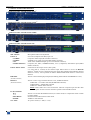
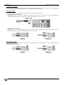
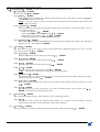
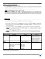
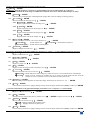
1-6. FRONT PANELS DESCRIPTION
• FRONT PANEL OF THE OCTO-PLUS
™
• FRONT PANEL OF THE OCTO-LOGO
™
• FRONT PANEL OF THE OCTO-FADE
™
• FRONT PANEL OF THE OCTO-FX
™
MIC LEVEL: Microphone audio level adjustment.
INPUT 8: Universal (computer and video) input # 8.
C.VIDEO: Composite Video input (RCA female connector).
S.VIDEO: S.VIDEO (Y/C) input (4-pin mini DIN female connector).
L+R: Audio stereo unbalanced input (jack 3.5 mm female connector).
COMPUTER/YUV: Computer (PC, MAC, WORKSTATION), YUV (component) and HDTV input (HD15
female connector).
INPUT SELECTION: • Selection of the 8 input sources (short push).
• A long push (1 second) on the selected input button allows to active the BLACK
function. A black screen is displayed onto the output (the blinking LED indicates that this
function is active). A short push on an INPUT SELECTION button allows to inactive this
function.
FREEZE: Allows to freeze the displayed output (the blinking LED indicates the FREEZE is active).
(OCP802 & OLG802)
EFFECT: Allows to select a type of effect between: CUT, FADE and TITLE.
(OFD802 & OFX802) • LED OFF = CUT effect selected (SEAMLESS transition).
• LED blinking = FADE effect selected.
• LED ON = TITLE effect selected.
NOTE:
These effects are active between the reference computer input and the other
inputs. In other cases the transition operates with a FADE COLOR.
LCD CONTROL
Allows to scroll thru the different menus (in Control mode) or to adjust the master volume
(in Status mode).
EXIT MENU: Switches between Status and Control mode.
ENTER: Validates a selected item.
ON / OFF: AC power switch (O = OFF, I = ON).

OCTO range
PAGE 8
Chapter 2 : STARTING
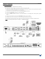
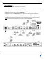
2-1. CONNECTIONS
c Turn OFF all of your equipment before connecting.
d Connect the AC Power supply cord to the OCTO and to an AC power outlet.
e Connect your Computer and video sources to the 8 inputs of the OCTO (7 inputs on the rear panel and one input on
the front panel). See next paragraphs for more information.
f Connect all of your audio sources to the corresponding AUDIO IN connectors.
g Connect the AUDIO OUT connector to your sound system.
h Connect the DISPLAY OUT connector to the DATA INPUT of your display device (data projector, plasma
screen...).
i Connect your microphone to the rear panel MIC (Bal) connector (jack 6.35 mm).
j If needed, connect your control device or the remote keypad to the RS-232 connector.
k Turn ON the OCTO (front panel switch). Then turn ON all yours input sources, and then your display device.
NOTE
: For switching operation please see Chapter 3 : OPERATING MODE.

OCTO range Chapter 2 : STARTING (continued)
PAGE 9
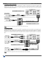
2-2. COMPOSITE VIDEO SOURCES
The Composite Video signal, usually called COMPOSITE or VIDEO is available on most video equipment (VCR, DVD,
CAMERA…), but it is also the lowest in picture quality. The video standard of this signal could be NTSC, PAL or
SECAM. The signal is transmitted by a single coaxial cable, and is connected to the video equipment with an RCA or BNC
connector.
NOTE:
The INPUT #8 is provided with a RCA connector (Front panel).
2-3. S.VIDEO SOURCES
The S.VIDEO signal, also called Y/C, HI-8
™
, or S.VHS
™
, is available on most DVD players and high quality VCR
(S.VHS). The S.VIDEO signal, in which the Luminance (Y) and Chrominance (C) information are separately transmitted
(2 wires), gives a higher quality picture than the Composite video signal. The S.VIDEO connector is usually a 4-pin
Mini-DIN connector also called Oshiden
™
connector. It can also sometimes be on 2 BNC connectors.
NOTE:
The INPUT #8 is provided with a 4-pin mini DIN female connector (Front panel).

Chapter 2 : STARTING (continued) OCTO range
PAGE 10
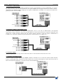
2-4. RGB/S VIDEO SOURCES
The RGB/S signal, also called RGB Sync., is an RGB signal with COMPOSITE Sync. This signal is widely used in
broadcasting. The RGB/S signal is transmitted with 4 coaxial cables, and it has a better picture quality than COMPOSITE
or S.VIDEO signals. The RGB/S connectors are usually BNC connectors.
2-5. COMPONENT VIDEO SOURCES (YUV)
The Component Video signal, also called YUV (Y, R-Y, B-Y), or BETACAM
™
, is widely used in broadcasting and is
available on high-quality DVD players. The COMPONENT signal is transmitted with 3 coaxial cables, and also has a
better picture quality than COMPOSITE and S.VIDEO signals. The COMPONENT connectors are usually RCA (x3), or
BNC (x3) connectors.
2-6. HDTV SOURCES
The OCTO accepts the 720p, 1035i and 1080i HDTV formats. Connect your HDTV sources as a component source.
2-7. COMPUTER SOURCES
The OCTO accepts COMPUTER signals (RGBHV, RGB/S, and RGsB) on its 8 inputs connector (HD15 female). Use a
HD15 male / male cable to connect each of your computer sources to the inputs of the OCTO. For MAC and
WORKSTATION you may require some adapters.

OCTO range Chapter 2 : STARTING (continued)
PAGE 11
2-8. DISPLAY OUTPUT
The OCTO is equipped with 2 buffered data outputs on HD15 female connectors. The OCTO can provide an RGBHV (H
& V Separate Sync.), an RGB/S (Composite Sync.) or an RGsB (SOG) output signal.
2-9. AUDIO INPUTS
Each audio input has a 3.5 mm jack female connector or a 5-pin MCO male connector.
• 3.5 mm jack female connector
The INPUTS # 6, 7, and 8 are equipped with this audio connector. This connector allows connecting only
UNBALANCED audio source. Connect your UNBALANCED audio sources as follow:
• 5-pin MCO male connector
The INPUTS # 1 to 5 are equipped with this connector. This connector allows connecting BALANCED or
UNBALANCED audio inputs. Connect your audio sources as follow:
2-10. AUDIO OUTPUT
The audio output is equipped with a 5-pin MCO male connector. This connector allows connecting BALANCED or
UNBALANCED audio systems.

OCTO range
PAGE 12
Chapter 3 : OPERATING MODE
The OCTO device can be used in two different switching modes.
• The SEAMLESS MODE, allows switching seamlessly, fading* and titling* between the "reference" COMPUTER input
and the others inputs. These ones are scaled to the same format as the "reference" COMPUTER format.
NOTE:
The inputs, which can be used as the "reference" Computer input, are the Input # 1 and # 8.
NOTE:
The "reference" Computer is not scaled.
• The FAST SWITCHING MODE (ultra smooth) allows selecting an output format corresponding to your application.
All video inputs are scaled to the selected format. The switching between two inputs will go through a fade colored
transition. The output rate can be selected between 60 Hz, 75 Hz or can be synchronized onto one of the video input
frame rate in order to improve the motion picture. In this case, the output frame rate will be 50 Hz if the input is in PAL
or SECAM, and 59.94 Hz if the input is in NTSC.
* On OCTO-FADE
™
& OCTO-FX
™
only.
3-1. SETTINGS
c We recommend resetting the OCTO device to all of its default values, with the LCD menu (CONTROL > default
value > yes) before proceeding.
d Select the input type connected to the INPUTS (# 1 to # 8) with the LCD menu (INPUT >input type).
e Select the output sync. type which corresponds to your display device with the LCD menu (OUTPUT > output
sync).
f Select a switching mode with the LCD menu (SWITCHING > fast switching or seamless). Please see the
Switching mode table below.
g If you have selected the fast switching mode: select one of the output formats with the LCD menu (OUTPUT >
output format).
NOTE
: For fixed pixels display device (DMD, LCD, PLASMA…), always select the output format corresponding
to the native resolution of your display device. Thus, the display device will not have to scale the image and
the result will be better.
NOTE:
In SEAMLESS mode, the output format is the same as the "reference" computer format.
h Select the type of screen (4/3 or 16/9) with the LCD menu (OUTPUT > type of screen), according to your wall
mounted projection screen shape.
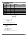
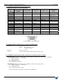
SWITCHING MODE TABLE
FAST SWITCHING
SWITCHING MODE
internal rate "input # x"
SEAMLESS
TRANSITION All switching with a fade color, a
fade frame** or a clean cut.
All switching with a fade
color, a fade frame** or a
clean cut.
• Seamless or fading* transition
between the "reference" computer
and all the inputs.
• All other switching with a fade
color a fade frame** or a clean cut.
OUTPUT FRAME
RATE
Generated by the OCTO (60 Hz or 75
Hz).
Synchronized on the selected
input frame rate (50 Hz if PAL
or SECAM and 59.94 Hz if
NTSC).
Synchronized on the "reference"
Computer frame rate (input # 1 or
input # 8).
OUTPUT FORMAT.
• VGA 60 Hz 4/3. • VGA 75 Hz 4/3.
• SVGA 60 Hz 4/3. • SVGA 75 Hz 4/3
• XGA 60 Hz 4/3. • XGA 75 Hz 4/3.
• SXGA 60 Hz 4/3. • SXGA 75 Hz 4/3
• SXGA+ 60 Hz 4/3
• D-ILA 75 Hz 4/3.
• D-ILA 75 Hz 16/9.
• HDTV 480p.
• HDTV 720p.
• 640 x 480 L.
• 800 x 600 L.
• 1024 x 768 L.
• 1280 x 1024 L.
• 1400 x 1050 L.
• 1365 x 1024 L.
• 1365 x 768 L.
• HDTV 480p.
• HDTV 720p.
Same format as the "reference"
Computer format.
* On OCTO-FADE
™
& OCTO-FX
™
only.
** On OCTO-LOGO
™
& OCTO-FX
™
only.

OCTO range Chapter 3 : OPERATING MODE (continued)
PAGE 13
3-2. SWITCHING OPERATIONS
The OCTO-PLUS
™
& OCTO-LOGO
™
allow switching between their inputs with 3 different effects: CUT, FADE COLOR
and CLEAN CUT. The OCTO-FADE
™
& the OCTO-FX
™
allow switching between their inputs with 4 different effects:
CUT, FADE, FADE COLOR and CLEAN CUT. The CUT effect allows switching seamlessly between 2 sources. The
FADE effect allows fading out the displayed source while another source is fading in. The FADE COLOR effect allows
switching between 2 sources with a fading to the color of you choice. The CLEAN CUT allows a clean switching thanks to
a fast freeze of the displayed source.
The OCTO-FADE
™
& the OCTO-FX
™
can also insert text onto the displayed image (TITLE effect).
IMPORTANT:
The CUT, FADE and TITLE effects are active in SEAMLESS mode and only between the reference
computer input and the other inputs.
• CUT (SEAMLESS):
c Select the reference computer input with the INPUT SELECTION button.
d Set the EFFECT button to CUT (EFFECT LED is OFF).
e Then select another input with the INPUT SELECTION button. The transition operates seamlessly.
• FADE (available on the OCTO-FADE
™
and the OCTO-FX
™
only):
c Select the reference computer input with the INPUT SELECTION button.
d Set the EFFECT button to FADE (EFFECT LED is blinking).
e Then select another input with the INPUT SELECTION button. The transition operates with a fading between
the two sources.
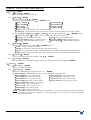
• TITLE (available on the OCTO-FADE
™
and the OCTO-FX
™
only):
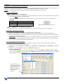
The TITLE effect allows to insert text onto an another source (video or computer). This effect is only active between
the reference input and the others inputs.
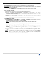
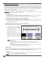
c Create the text to display with the computer
connected to the reference input, thanks to a
drawing software like Power Point (text in
white onto a black background).
d Select the source to titling (INPUT #3 in the
example opposite).
e Set the EFFECT button to TITLE (EFFECT
LED is ON).
f Then select the reference computer input
(INPUT #1 in the example opposite). The
text appears onto the displayed image.
NOTE:
• For a better readability, you can
display a shadow bar onto your text (EFFECT > shadow title > on).
• To display OFF the text, press on the button of the reference computer input.
• To display OFF the background image (INPUT #3 in our example), press on the INPUT #3 button.
• To switch between sources without displaying OFF the text, press on the button of the needed source.
The transition operates with a fade color.
• The BLACK function is not available when the TITLE effect is active.
• FADE COLOR:
The FADE COLOR allows switching between 2 sources with a fading to a color of you choice. This transition operates
in Fast Switching mode and sometimes in Seamless mode (only when the others effects are not possible). You can
select the color of the fading with the LCD CONTROL menu.
• CLEAN CUT:
The CLEAN CUT allows a clean switching thanks to a fast freeze of the displayed source. Activate the CLEAN
CUT with the LCD menu (CONTROLS > transition > clean cut).
NOTE:
The FRAME is not available when the CLEAN CUT is activated.

Chapter 3 : OPERATING MODE (continued) OCTO range
PAGE 14
3-3. DISPLAY DEVICE ADJUSTMENTS
• IN SEAMLESS MODE:
c Select the reference computer source. The reference computer image is displayed onto the output.
d Adjust directly the display device itself, using its position and size controls, to fill the computer image in full screen.
e Select another source or the Black screen then displays the centering pattern with the LCD menu (OUTPUT > test
pattern > centering).
f Adjust the centering pattern position with the LCD menu (OUTPUT > test pattern > centering >...), to fill the
centering pattern in full screen.
• IN FAST SWITCHING MODE:
c Display the centering pattern with the LCD menu (OUTPUT > test pattern > centering).
d Display a black output.
e Adjust directly the display device itself, using its position and size controls, to fill the centering pattern in full
screen.
3-4. IMAGE ADJUSTMENTS
For each input source connected to the OCTO, make the following adjustments:
NOTE:
In seamless mode the reference computer input can not be adjusted.
c Select the source you want to adjust (with the front panel "INPUT SELECTION" buttons).
d Select the aspect ratio of your input source with the LCD menu (IMAGE > aspect ratio).
e Use the Centering function (IMAGE > centering) to automatically position the image in the Centering pattern.
IMPORTANT: For best results, display a full size bright image (no black border) to perform a centering. If
necessary, correct the adjustment with the position & size functions (IMAGE > pos settings).
NOTE:
The centering function is only available for computer sources.
NOTE:
In case of same Input/Output resolution, the centering also achieves automatic pixel clock adjustments. It
may be useful, to improve manually the pixel clock and phase using the LCD menu (IMAGE > optimize
> clock or phase).
f If needed, make the others adjustments, available in the LCD IMAGE menu (color, brightness…).
NOTE:
To set the image adjustments to the factory settings, use the Preset function (IMAGE > preset > yes).
NOTE: The adjustments are automatically stored in NON-volatile memories. The OCTO is provided with 40 NON-
volatile image memories. Each of these memories contains the input channel number, the input and output
format parameters and all of the image adjustments (position, size, brightness...). When the 40 memories
are used, each new memorization erases the oldest record.
3-5. AUDIO ADJUSTMENTS
c Adjust the master volume (AUDIO > master volume).
d Set the auto follow or breakaway audio mode (AUDIO > audio source > auto follow or input # x):
- auto follow = the audio switching follows automatically the video switching.
- breakaway = the selected audio input is permanently diffused.
e For each audio input, adjust the level (AUDIO > audio level) and the balance (AUDIO > audio balance).
f Adjust your microphone (AUDIO > mic-control).

OCTO range
PAGE 15
Chapter 4 : USING FRAME STORE AND LOGO INSERTION
NOTE: This chapter concerns the OCTO-LOGO
™
and the OCTO-FX
™
device only.
4-1. LOGO INSERTION
This function allows storing up to 8 logos in order to incrust them into the displayed image (up to 2 logos at the same time).
IMPORTANT:
• The output format used when displaying logo should be the same that the output format used during the
logo storing.
• In SEAMLESS mode, the referenced input cannot be used to acquire or displays logos.
• HOW TO STORE A LOGO:
c Select the source of the logo to be stored (with the INPUT SELECTION buttons).
d Select the record logo mode (LOGOS/FRAME > record logo): the device displays a white rectangle
corresponding to the logo selection area onto the output. Then adjust the position and size of the logo selection area
with the LCD record logo menu functions.
NOTE
: The logo area is limited to an eighth (1/8) of the displayed area.
e If necessary, adjust the luma key level (LOGOS/FRAME > record logo > luma key level). This function allows
to "erase" the darkest portions of your the logo selection area in order to make special logo contour. Otherwise set
the luma key level to zero.
NOTE:
You can change the color of the "erased portions" of the logo (LOGOS/FRAME > record logo > back.
color).
f Store the logo into a memory (LOGOS/FRAME > record logo > store > empty or logo x). The memorization of
the logo starts and will take about few seconds.
NOTE:
Renew the steps c to f to store another logos (up to 8).
• HOW TO ASSIGN A LOGO:
NOTE:
You can assign the stored logos to one or many of the 8 inputs (up to 2 logos by inputs).
g In the assignment menu (LOGOS/FRAME > use logo/frame > assignment), select the input that you want to
assign a logo, then select an index (1 or 2) and finally select the needed logo.
NOTE:
To remove a logo from an input, select the corresponding input & index and select none.
h With the INPUT SELECTION buttons, display successively all your inputs to verify your logo assignment. If no
logo appears on an input: verify that the LCD display function of the corresponding input is not set to the OFF
position. In this case press ENTER to set it to the ON position (See how to display OFF or ON a logo).
• HOW TO DISPLAY OFF or ON A LOGO:
i To display OFF or ON the assigned logos of an input, select the corresponding input in the display menu
(LOGOS/FRAME > use logo/frame > display) and press ENTER to change the status (ON or OFF).
NOTE:
When displaying ON or OFF a logo, this one appears/disappears with a fade effect. You can adjust the
duration of this fade effect (LOGOS/FRAME > use logo/frame > fade duration).
• HOW TO ADJUST THE LOGO POSITION:
j Select the input with the logo to be adjusted (with the INPUT SELECTION buttons).
k In the assignment menu (LOGOS/FRAME > use logo/frame > assignment), select the input and the logo to
adjust. Then adjust the logo position with the H &V position functions.
NOTE:
When you are using 2 logos by input, make sure to not superpose a logo onto an other one. In case of
superposition, the logo areas will appear colored.
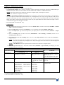
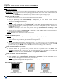
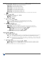
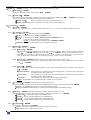
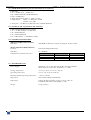
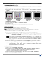
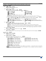
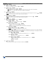
• EXAMPLE OF LOGO INSERTION:
Logo source Video source Video source with inserted logo.
(white border = logo area) (logo made with luma key)

Chapter 4 : USING FRAME STORE AND LOGO INSERTION (continued) OCTO range
PAGE 16
4-2. FRAME STORE
This function allows memorizing a frame (an image) in order to display it at any time during the show.
IMPORTANT
: • The output format used when displaying the frame should be the same that the output format used
during the FRAME storing.
• In SEAMLESS mode, the referenced input cannot be used to acquire or displays a frame.
• The FRAME is not available when the CLEAN CUT is activated.
• HOW TO STORE A FRAME:
c Select the source of the frame to be stored (with the INPUT SELECTION buttons).
d Select the record frame mode (LOGOS/FRAME > record frame): the device displays a white rectangle
corresponding to the frame selection area onto the output. If necessary adjust the position and size of the frame
selection area (IMAGE > pos settings).
e Store the frame (LOGOS/FRAME > record frame > store). The memorization starts and will take about 2
minutes.
NOTE:
For motion picture, you can use the FREEZE function, before doing the memorization.
• HOW TO ASSIGN A FRAME:
f In the assignment menu (LOGOS/FRAME > use logo/frame > assignment), select the input that you want to
assign the FRAME, then select an INDEX (1 or 2) and select frame.
NOTE:
To remove the FRAME from an input, select the corresponding input & index and select none.
• HOW TO DISPLAY ON or OFF the FRAME:
g To display ON the FRAME, select the input corresponding to the frame with the INPUT SELECTION buttons. The
FRAME appears onto the output, instead of the source connected to this input.
NOTE:
If the FRAME doesn't appear: verify that the display function of the corresponding input is not set in the
OFF position (LOGOS/FRAME > use logo/frame > display). In this case, presses ENTER to set it in the
ON position.
h To display OFF the frame, set the display function in OFF position (LOGOS/FRAME > use logo/frame > display
> OFF).
TRICK:
To quickly display ON or OFF the FRAME, assign the FRAME to an unused input, and set the display
function in the ON position. Also to display ON the FRAME, press the corresponding INPUT
SELECTION button and then select another input to display OFF.

OCTO range
PAGE 17
Chapter 5 : LCD SCREEN DESCRIPTION
5-1. INTRODUCTION
The LCD screen is composed of 2 modes: the STATUS MODE and the CONTROL MODE.
• The STATUS MODE indicates the input and output status of the OCTO.
• The CONTROL MODE allows selecting and adjusting the parameters of the OCTO.
5-2. CONTROL BUTTONS
The LCD screen is controlled by 2 buttons and 1 knob:
knob: • In the STATUS MODE, turns this knob to adjust the Master volume.
• In the CONTROL MODE, turn this knob to scroll thru the different menus.
EXIT / MENU button: • In the STATUS MODE, press this button to display the CONTROL MODE.
• In the CONTROL MODE, press this button to:
- return to the previous menu without safeguarding the selection.
- return to the STATUS MODE (press several times).
ENTER button: • From the STATUS MODE, press this button to display the CONTROL MODE.
• From the CONTROL MODE, press this button to confirm a selected item.
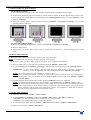
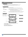
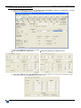
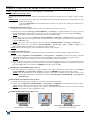
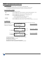
5-3. STATUS MODE
When switching ON, the LCD SCREEN shows the product's name and reference as follows:
DEVICE NAME OCTO-FADE DEVICE STATUS
DEVICE VERSION Version _._
OUTPUT XGA d OUTPUT STATUS
c intern rate 60 Hz e
f INPUT # 1 INPUT STATUS
g SVGA 37.9 K / 60Hz h
c SEAMLESS MODE or FAST SWITCHING MODE (OUTPUT RATE).
d OUTPUT FORMAT.
e OUTPUT FRAME RATE.
f SELECTED INPUT (DISPLAYED).
g INPUT FORMAT OR INPUT STANDARD.
h INPUT LINE / FRAME FREQUENCY.

Chapter 5 : LCD SCREEN DESCRIPTION (continued) OCTO range
PAGE 18
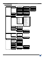
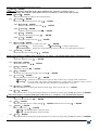
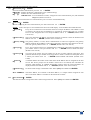
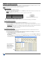
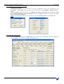
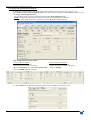
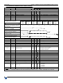
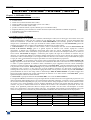
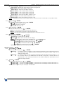
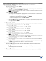
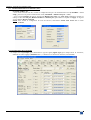
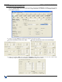
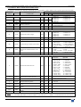
5-4. CONTROL MODE
The menus of the CONTROL MODE are configured as follow:
3 used input
5 VCR mode
[
i
n
t
erna
l
]
[ input #1 ]
…..
[
in
p
ut #8
]
2 seamless seamless
3 output sync output sync
H&V COMP SOG
4 H. sync. load
4 type of screen
1 screen 4/3
1 INPUT 1 input status 1 SDTV Composite 1 NTSC/PAL/SECAM
2 input type
1 #1 Comp. HV/C
2 SDTV S.VIDEO
2 NTSC
2 #2 Comp. HV/C
3 SDTV YUV
4 PAL
3 #3 Comp. HV/C
4 SDTV RGBS TTL
4 #4 Comp. HV/C
5 SDTV RGB SOG
7 B&W 50/60Hz
5 #5 Comp. HV/C
6 SDTV RGBS ana. 6 SECAM
6 #6 Comp. HV/C
7 Computer SOG
7 #7 Comp. HV/C
8 Computer HV/C
2 Input # 2
2 unused
8 #8 Comp. HV/C
9 HDTV
9 All inputs
10 Audio only.
1 Input # 1
2 OUTPUT 1 output status
2 output format
……………
8 Input # 8
I
N
T
E
R
N
A
L
R
A
T
E
3 NTSC 4,43 60Hz
5 PAL 4,43 60 Hz
3 freeze
1
4 dis
p
la
y
lo
g
o
2
1 used
2 screen 16/9
5 test pattern 1 no pattern
2 centering 1 H. position
3 color ba
r
2 V. position
3 H. size
4 V. size
3 SWITCHING 1 fast switching output rate
[ computer #1 ]
[
com
p
uter #8
]
1 output 4/3
2 output 16/9
4 IMAGE 1 centering
2 pos settings 1 H. position
2 V. position
3 H. size
4 V. size
3 aspect ratio
1 4/3 standard
2 16/9 letterbox
4 H. smooth
3 WS anamorphic
IF VIDEO INP UT IF COM PUTER INPUT
5 brightness
5 black level
6 contrast 6 color 1 Red level
7 color 2 Green level
10 sharpness
8 preset 2 phase
11 preset
1
available on OFD802 & OFX802 only.
2
available on OFX802 only.
1 640x480L
2 800x600L
3 1024x768L
4 1280x1024L
5 1400x1050L
6 1365x1024L
7 1365x768L
8 HDTV 480p
9 HDTV 720
p
I
N
P
U
T
R
A
T
E
1 VGA 60Hz 4/3
2 SVGA 60Hz 4/3
3 XGA 60Hz 4/3
4 SXGA 60Hz 4/3
5 SXGA+ 60Hz 4/3
6 VGA 75Hz 4/3
7 SVGA 75Hz 4/3
8 XGA 75Hz 4/3
9 SXGA 75Hz 4/3
11 D-ILA 75Hz 4/3
12 D-ILA 75Hz 16/9
13 HDTV 480p
14 HDTV 720p
8 hue 3 Bleu level
9 under/over
7 optimize 1 clock

OCTO range Chapter 5 : LCD SCREEN DESCRIPTION (continued)
PAGE 19
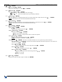
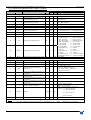
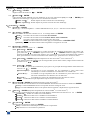
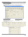
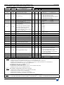
5-4. CONTROL MODE (continued)
6 mute ON
1 auto follow
2 input # 1
…..
9 input # 8
8 input # 8 OFF
2 depth
1 threshold
3 release time
4 audio balance
5 mic. control
1 tone
4 voice over
5
6 LOGOS/FRAME
3
1 use logo/frame 1 input #1 ON
……………
4 freeze button
4
button assign to
freeze lo
g
o
……………
1 display
2 green level
2 fade frame
3
1 input # 1
5 luma key level
6 back. colo
r
7 store
2 remote addr.
6
3
g
atewa
y
addr.
6
8 erase memories no yes
select address
xxx.xxx.xxx.xxx
4 effect ke
y
1
1 cut fade title
5 AUDIO 1 master volume
2 audio source
3 audio level
2 com
p
ression
3 noise
g
ate
2 assignment Index 1
logo 2 1 none
3 fade duration 2 input # 2 Index 2 none 2 frame
3 logo 1
2 record logo 1 H. position
8 input # 8 4 empty
2 V. position
……
3 H. size
10 logo 8
4 V. size
3 record frame 1 store
4 erase
7 EFFECT
1
1 fade timing
fade timing
===== 3.5 s
2 shadow title
Shadow title
OFF ON
1 shadow V size
2 shadow V pos.
8 CONTROL 1 versions
2 key locking
1 red level3 transition 1 fade color
2 cut fade
3 cut title
4 title fade
5 2:2 pull down auto of
f
6
available with the LAN option.
6 RS232/LAN port
comm port select
RS232 LAN
select port
xxxxx
5 remote
p
ort
6
4 local
p
ort
6
7 LAN setup
1 local addr.
6
9 default value no yes
3
available on OLG802 & OFX802 only.
select netmask
xxx.xxx.xxx.xxx
7 default setu
p
6
6 netmask
6
4
available on OLG802 only.
5
available with the voice over option.
3 bleu level
3 clean cut 1 from compute
r
2 from video
3 from all
9 FREEZE OFF
1
1
available on OFD802 & OFX802 only.
2
available on OFX802 only.

OCTO range
PAGE 20
Chapter 6 : LCD FUNCTIONS DESCRIPTION
1[INPUT] + ENTER.
1-1 [input status] + ENTER.
Indicates the status of the selected input.
1-2 [input type] + ENTER.
c Select an input with + ENTER.
d Select the input signal type with + ENTER between:
• [SDTV Composite] • [SDTV RGB SOG]
• [SDTV S.VIDEO] • [SDTV RGBS ana.]
• [SDTV YUV] • [Computer SOG]
• [SDTV RGBS TTL] • [Computer HV/C]
• [HDTV] = HDTV input format (720p, 1035i and 1080i).
• [Audio only] = select this function if you only want to connect an audio source (no video signal needed).
e Then for [SDTV Composite], and [SDTV S.VIDEO], select the video standard with + ENTER between:
• [NTSC / PAL / SECAM] = automatic NTSC, PAL, and SECAM standard detection.
• [NTSC] = NTSC standard detection only. • [PAL] = PAL standard detection only.
• [NTSC 4.43 60 Hz] = NTSC 4.43 60Hz detection. • [PAL 4.43 60Hz] = PAL 4.43 60Hz detection.
• [SECAM] = SECAM standard detection only. • [B & W 50/60 Hz] = Black and White detection.
1-3 [used input] + ENTER.
Select an input and then select an item + ENTER between:
• [used] = A signal is connected to the input.
• [unused] = No signal is connected to the input. The input is unused.
• [freeze] = The input button is assign to the FREEZE function (available on the OFD802 & OFX802 only).
• [display logos] = The input button is assign to the display logos function (available on the OFX802 only).
1-4 [H sync load] + ENTER.
Select for each input the load of the H Sync. with + ENTER.
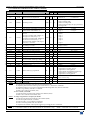
1-5 [VCR mode] + ENTER.
This function allows improving the image contour of low quality VHS tapes. Select [on] with ENTER.
2[OUTPUT] + ENTER.
2-1 [output status] + ENTER.
Indicates the status of the output.
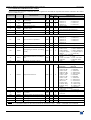
2-2 [output format] + ENTER.
Select one of the following output format with + ENTER.
• If [fast switching] = [internal rate], the LCD window displays the following formats :
• [VGA 60 Hz 4/3] = 640 x 480 at 60 Hz. • [VGA 75 Hz 4/3] = 640 x 480 at 75 Hz.
• [SVGA 60 Hz 4/3] = 800 x 600 at 60 Hz. • [SVGA 75 Hz 4/3] = 800 x 600 at 75 Hz.
• [XGA 60 Hz 4/3] = 1024 x 768 at 60 Hz. • [XGA 75 Hz 4/3] = 1024 x 768 at 75 Hz.
• [SXGA 60 Hz 4/3] = 1280 x 1024 at 60 Hz. • [SXGA 75 Hz 4/3] = 1280 x 1024 at 75 Hz.
• [SXGA+ 60 Hz 4/3] = 1400 x 1050 at 60 Hz.
• [D-ILA - 4/3] = 1365 x 1024 at 75 Hz.
• [D-ILA - 16/9] = 1365 x 768 at 75 Hz.
• [HDTV 480p] = 853 x 480 at 60 Hz.
• [HDTV 720p] = 1280 x 720 at 60 Hz.
NOTE
: For fixed pixels display devices (DMD, LCD, PLASMA…), always select the output format corresponding
to the native resolution of the display device. Thus, the display device will not have to scale the image and
the result will be better.
La page est en cours de chargement...
La page est en cours de chargement...
La page est en cours de chargement...
La page est en cours de chargement...
La page est en cours de chargement...
La page est en cours de chargement...
La page est en cours de chargement...
La page est en cours de chargement...
La page est en cours de chargement...
La page est en cours de chargement...
La page est en cours de chargement...
La page est en cours de chargement...
La page est en cours de chargement...
La page est en cours de chargement...
La page est en cours de chargement...
La page est en cours de chargement...
La page est en cours de chargement...
La page est en cours de chargement...
La page est en cours de chargement...
La page est en cours de chargement...
La page est en cours de chargement...
La page est en cours de chargement...
La page est en cours de chargement...
La page est en cours de chargement...
La page est en cours de chargement...
La page est en cours de chargement...
La page est en cours de chargement...
La page est en cours de chargement...
La page est en cours de chargement...
La page est en cours de chargement...
La page est en cours de chargement...
La page est en cours de chargement...
La page est en cours de chargement...
La page est en cours de chargement...
La page est en cours de chargement...
La page est en cours de chargement...
La page est en cours de chargement...
La page est en cours de chargement...
La page est en cours de chargement...
La page est en cours de chargement...
La page est en cours de chargement...
La page est en cours de chargement...
La page est en cours de chargement...
La page est en cours de chargement...
La page est en cours de chargement...
La page est en cours de chargement...
La page est en cours de chargement...
La page est en cours de chargement...
La page est en cours de chargement...
La page est en cours de chargement...
La page est en cours de chargement...
La page est en cours de chargement...
La page est en cours de chargement...
La page est en cours de chargement...
La page est en cours de chargement...
La page est en cours de chargement...
La page est en cours de chargement...
La page est en cours de chargement...
La page est en cours de chargement...
La page est en cours de chargement...
La page est en cours de chargement...
La page est en cours de chargement...
La page est en cours de chargement...
La page est en cours de chargement...
-
 1
1
-
 2
2
-
 3
3
-
 4
4
-
 5
5
-
 6
6
-
 7
7
-
 8
8
-
 9
9
-
 10
10
-
 11
11
-
 12
12
-
 13
13
-
 14
14
-
 15
15
-
 16
16
-
 17
17
-
 18
18
-
 19
19
-
 20
20
-
 21
21
-
 22
22
-
 23
23
-
 24
24
-
 25
25
-
 26
26
-
 27
27
-
 28
28
-
 29
29
-
 30
30
-
 31
31
-
 32
32
-
 33
33
-
 34
34
-
 35
35
-
 36
36
-
 37
37
-
 38
38
-
 39
39
-
 40
40
-
 41
41
-
 42
42
-
 43
43
-
 44
44
-
 45
45
-
 46
46
-
 47
47
-
 48
48
-
 49
49
-
 50
50
-
 51
51
-
 52
52
-
 53
53
-
 54
54
-
 55
55
-
 56
56
-
 57
57
-
 58
58
-
 59
59
-
 60
60
-
 61
61
-
 62
62
-
 63
63
-
 64
64
-
 65
65
-
 66
66
-
 67
67
-
 68
68
-
 69
69
-
 70
70
-
 71
71
-
 72
72
-
 73
73
-
 74
74
-
 75
75
-
 76
76
-
 77
77
-
 78
78
-
 79
79
-
 80
80
-
 81
81
-
 82
82
-
 83
83
-
 84
84


Analog way OCTO-FADE Manuel utilisateur
- Taper
- Manuel utilisateur
dans d''autres langues
- English: Analog way OCTO-FADE User manual
Documents connexes
Autres documents
-
DeLOCK 62499 Fiche technique
-
 StarTech.com S-Video m/m 5.5m Fiche technique
-
Extron IN2160 Manuel utilisateur
-
 ADS Technologies TV ELITE XGA Manuel utilisateur
-
 JBSYSTEMS LED OCTO PANEL Le manuel du propriétaire
-
Korg KF4 Le manuel du propriétaire
-
InLine IN2081 Mode d'emploi
-
Hama 00042513 Le manuel du propriétaire
-
Propellerhead REASON 5 Le manuel du propriétaire
-


