Fujitsu ASGA18FUTC-B Guide d'installation
- Catégorie
- Climatiseurs split-system
- Taper
- Guide d'installation
Ce manuel convient également à

En-1
Note: This manual describes how to install the air conditioner described above. Handling
and installation shall only be done by professionals as outlined in this manual.
1. SAFETY PRECAUTIONS
1
x
Be sure to read this manual thoroughly before installation.
x
The warnings and precautions indicated in this manual contain important informa-
tion pertaining to your safety. Be sure to observe them.
x
Hand this manual, together with the operating manual, to the customer. Request
the customer to keep them on hand for future use, such as for relocating or repair-
ing the product.
WARNING
Indicates a potentially or imminently hazardous situation which,
if not avoided, could result in death or serious injury.
Installation of this product must be done by experienced service technicians
or professional installers only in accordance with this manual. Installation by
nonprofessional or improper installation of the product may cause serious accidents
such as injury, water leakage, electric shock, or fire. If the product is installed in
disregard of the instructions in this Manual, it will void the manufacturer’s warranty.
Do not turn on the power until all work has been completed. Turning on the power before
WKHZRUNLVFRPSOHWHGFDQFDXVHVHULRXVDFFLGHQWVVXFKDVHOHFWULFVKRFNRU¿UH
If refrigerant leaks when you are working, ventilate the area. If the leaking refrigerant is
H[SRVHGWRDGLUHFWÀDPHLWPD\SURGXFHDWR[LFJDV
'RQRWXVHWKLVHTXLSPHQWZLWKDLURUDQ\RWKHUXQVSHFL¿HGUHIULJHUDQWLQWKHUHIULJHUDQW
lines. Excess pressure can cause a rupture.
Installation must be performed in accordance with regulations, codes, or standards for
electrical wiring and equipment in each country, region, or the installing place.
'R QRW WRXFK WKH ¿QV RI WKH KHDW H[FKDQJHU 7RXFKLQJ WKH KHDW H[FKDQJHU ¿QV FRXOG
UHVXOWLQGDPDJHWRWKH¿QVRUSHUVRQDOLQMXU\VXFKDVVNLQUXSWXUH
This appliance is not intended for use by persons (including children) with reduced
physical, sensory or mental capabilities, or lack of experience and knowledge, unless
they have been given supervision or instruction concerning use of the appliance by a
person responsible for their safety. Children should be supervised to ensure that they do
not play with the appliance.
CAUTION
Indicates a potentially hazardous situation that may result in
minor or moderate injury or damage to property.
Read carefully all safety information written in this manual before you install or use the
air conditioner.
Install the product by following local codes and regulations in force at the place of
installation, and the instructions provided by the manufacturer.
This product is part of a set constituting an air conditioner. The product must not be
installed alone or be installed with non-authorized device by the manufacturer.
Always use a separate power supply line protected by a circuit breaker operating on all
wires with a distance between contact of 3 mm for this product.
To protect the persons, earth (ground) the product correctly, and use the power cable
combined with an Earth Leakage Circuit Breaker (ELCB).
The product is not explosion proof, and therefore should not be installed in explosive
atmosphere.
To avoid getting an electric shock, never touch the electrical components soon after the
power supply has been turned off. After turning off the power, always wait 5 minutes or
more before you touch the electrical components.
This product contains no user-serviceable parts. Always consult experienced service
technicians for repairing.
When moving or relocating the air conditioner, consult experienced service technicians
for disconnection and reinstallation of the product.
Do not place any other electrical products or household belongings under the product.
Condensation dripping from the product might get them wet, and may cause damage or
malfunction of the property.
2. ABOUT THIS PRODUCT
2.1. Precautions for using R410A refrigerant
The basic installation work procedures are the same as conventional refrigerant (R22)
models.
However, pay careful attention to the following points:
Since the working pressure is 1.6 times higher than that of conventional refrigerant (R22)
models, some of the piping and installation and service tools are special. (See the table
below.)
Especially, when replacing a conventional refrigerant (R22) model with a new refrigerant
5$PRGHODOZD\VUHSODFHWKHFRQYHQWLRQDOSLSLQJDQGÀDUHQXWVZLWKWKH5$
SLSLQJDQGÀDUHQXWV
Models that use refrigerant R410A have a different charging port thread diameter
to prevent erroneous charging with conventional refrigerant (R22) and for safety.
Therefore, check beforehand. [The charging port thread diameter for R410A is
1/2-20 UNF]
Be more careful that foreign matter (oil, water, etc.) does not enter the piping than with
refrigerant (R22) models. Also, when storing the piping ,securely seal the opening by
pinching, taping, etc.
When charging the refrigerant, take into account the slight change in the composition of
the gas and liquid phases. And always charge from the liquid phase where refrigerant
composition is stable.
1
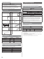
2.2. Special tools for R410A refrigerant
Tool name Changes
Gauge manifold
Pressure is high and cannot be measured with a conventional
(R22) gauge. To prevent erroneous mixing of other refriger-
ants, the diameter of each port has been changed.
It is recommended to use the gauge with seals-0.1 to 5.3 MPa
(-1 to 53 bar) for high pressure.
-0.1 to 3.8 MPa (-1 to 38 bar) for low pressure.
Charge hose
To increase pressure resistance, the hose material and base
size were changed.
Vacuum pump
A conventional vacuum pump can be used by installing a
vacuum pump adapter.
Gas leakage detector
Special gas leakage detector for HFC refrigerant R410A.
Copper pipes
It is necessary to use seamless copper pipes and it is desirable that the amount of re-
sidual oil is less than 40 mg/10 m. Do not use copper pipes having a collapsed, deformed
or discoloured portion (especially on the interior surface). Otherwise, the expansion value
or capillary tube may become blocked with contaminants.
As an air conditioner using R410A incurs pressure higher than when using R22, it is neces-
sary to choose adequate materials.
AIR CONDITIONER
INDOOR UNIT (Wall Mounted Type)
INSTALLATION MANUAL
PART No. 9387082241
For authorized service personnel only.
Refer to the rating label with the serial number.
Contents
1. SAFETY PRECAUTIONS ................................................................. 1
2. ABOUT THIS PRODUCT..................................................................1
3. GENERAL SPECIFICATION ............................................................2
4. SELECTING THE INSTALLATION LOCATION ................................ 3
5. INSTALLATION WORK .................................................................... 3
6. ELECTRICAL WIRING ..................................................................... 5
7. FINISHING........................................................................................6
8. FRONT PANEL REMOVAL AND INSTALLATION ........................... 7
9. REMOTE CONTROLLER INSTALLATION ....................................... 7
10. OPTIONAL KIT INSTALLATION ....................................................... 8
11. FUNCTION SETTING...................................................................... 8
12. CHECK LIST ..................................................................................... 9
13. TEST RUN ........................................................................................ 9
14. CUSTOMER GUIDANCE ................................................................. 9
15. ERROR CODES ............................................................................ 10
English

En-2
CONNECTION PIPE REQUIREMENT
WARNING
'RQRWXVHWKHH[LVWLQJIRU5SLSLQJDQGÀDUHQXWV
If the existing materials are used, the pressure inside the refrigerant cycle will rise
and cause failure, injury, etc. (Use the special R410A materials.)
When installing and relocating the air conditioner, do not mix gases other
WKDQWKHVSHFL¿HGUHIULJHUDQW5$WRHQWHUWKHUHIULJHUDQWF\FOH
If air or other gas enters the refrigerant cycle, the pressure inside the cycle will rise
to an abnormally high value and cause failure, injury, etc.
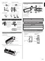
2.3. Accessories
The following installation accessories are supplied. Use them as required.
Name and Shape Q’ty Name and Shape Q’ty
Operating Manual
1
Remote controller
holder
1
Installation Manual
2
Insulation (Drain hose)
1
6SHFL¿FDWLRQ0DQXDO
1
Cloth tape
1
Wall hook bracket
1
Tapping screw (large)
8
Remote controller
1
Tapping screw (small)
2
Battery
2
2.4. Optional parts
Refer to each installation manual for the method of installing optional parts.
Parts name Model No. Application
Wired Remote Controller* UTY-RNN*M For air conditioner operation
$SSOHFDWHFKLQ¿OWHU UTR-FA13-1
,RQGHRGRUL]DWLRQ¿OWHU UTR-FA13-2
External connect kit* UTY-XWZXZ5 For control input/output port
Communication kit UTY-XCBXZ3
For the installation of optional
parts
* Optional communication kit is necessary for the installation.
2.5. Additional materials required for installation
The following items are necessary to install this air conditioner. (The items are not includ-
ed with the air conditioner and must be purchased separately.)
Name
Connection pipe assembly Saddle
Connection cable Drain hose
Wall pipe Tapping screws
Decorative tape Sealant
Vinyl tape M10 bolt, nut
Wall cap
3. GENERAL SPECIFICATION
This Installation manual briefly outlines where and how to install the air conditioning
system. Please read over the entire set of instructions for the indoor and outdoor units and
make sure all accessory parts listed are with the system before beginning.
3.1. Type of copper pipe and insulation material
]1
CAUTION
Refer to the installation manual for the outdoor unit for description of allowable pipe
length and height difference.
Diameter
Liquid pipe Gas pipe
30/36 type 9.52 mm (3/8 in.) 15.88 mm (5/8 in.)
18/24 type 6.35 mm (1/4 in.) 15.88 mm (5/8 in.)
CAUTION
Install heat insulation around both the gas and liquid pipes. Failure to do so may cause
water leaks.
Use heat insulation with heat resistance above 120 °C. Reverse cycle model only
In addition, if the humidity level at the installation location of the refrigerant piping is
expected to exceed 70%, install heat insulation around the refrigerant piping. If the
expected humidity level is 70-80%, use heat insulation that is 15 mm or thicker and if the
expected humidity exceeds 80%, use heat insulation that is 20 mm or thicker.
,IKHDWLQVXODWLRQLVXVHGWKDWLVQRWDVWKLFNDVVSHFL¿HGFRQGHQVDWLRQPD\IRUPRQWKH
surface of the insulation. In addition, use heat insulation with heat conductivity of
:P.RUOHVVDW&
3.2. Electrical requirement
The indoor unit is powered from the outdoor unit or branch box. Do not power indoor unit
from separate power source.
WARNING
Refer to local codes for acceptable cable type.
Cable
Cable size (mm
2
)
Type
Remarks
Connection cable
1.5 ~ 2.5 Type 60245 IEC 57
*Refer to “Outdoor unit installation
manual”
Max. Cable Length: Limit voltage drop to less than 2%. Increase cable gauge if voltage
drop is 2% or more.
Before starting work check that power is not being supplied to all poles of the indoor
unit and outdoor unit.
Install all electrical works in accordance to standard.
Install the disconnect device with a contact gap of at least 3mm in all poles nearby the
units. (Both indoor unit and outdoor unit)
Wiring size must comply with the applicable local and national code.

En-3
4. SELECTING THE INSTALLATION LOCATION
Decide the mounting position with the customer as follows:
WARNING
Select installation locations that can properly support the weight of the indoor unit
and which will not amplify sound or vibration. If the installation location is not strong
enough, the indoor unit may fall and cause injuries.
Install the units securely so that they do not topple or fall.
CAUTION
Do not install the unit in the following areas:
$UHDZLWKKLJKVDOWFRQWHQWVXFKDVDWWKHVHDVLGH,WZLOOGHWHULRUDWHPHWDOSDUWV
causing the parts to fail or the unit to leak water.
$UHD¿OOHGZLWKPLQHUDORLORUFRQWDLQLQJDODUJHDPRXQWRIVSODVKHGRLORUVWHDP
such as a kitchen.
It will deteriorate plastic parts, causing the parts to fail or the unit to leak water.
$UHDWKDWJHQHUDWHVVXEVWDQFHVWKDWDGYHUVHO\DIIHFWWKHHTXLSPHQWVXFKDV
sulphuric gas, chlorine gas, acid, or alkali.
It will cause the copper pipes and brazed joints to corrode, which can cause
refrigerant leakage.
$UHDWKDWFDQFDXVHFRPEXVWLEOHJDVWROHDNFRQWDLQVVXVSHQGHGFDUERQ¿EUHVRU
ÀDPPDEOHGXVWRUYRODWLOHLQÀDPPDEOHVVXFKDVSDLQWWKLQQHURUJDVROLQH
,IJDVOHDNVDQGVHWWOHVDURXQGWKHXQLWLWFDQFDXVHD¿UH
$UHDZKHUHDQLPDOVPD\XULQDWHRQWKHXQLWRUDPPRQLDPD\EHJHQHUDWHG
Do not use the unit for special purposes, such as storing food, raising animals, growing
plants, or preserving precision devices or art objects.
It can degrade the quality of the preserved or stored objects.
Do not install where there is the danger of combustible gas leakage.
'RQRWLQVWDOOWKHXQLWQHDUDVRXUFHRIKHDWVWHDPRUÀDPPDEOHJDV
Install the unit where drainage does not cause any trouble.
Install the unit where ambient temperature does not reach 60°C or more. Take a
measure such as ventilation for an environment in which heat is retained.
If children under 10 years old may approach the unit, take preventive measures so
that they cannot reach the unit.
,QVWDOOWKHLQGRRUXQLWRQWKHZDOOZKHUHWKHKHLJKWIURPWKHÀRRUVPRUHWKDQP
(1) Install the indoor unit level on a strong wall which is not subject to vibration.
(2) The inlet and outlet ports should not be obstructed: the air should be able to blow all
over the room.
(3) Install the unit at a place near an power outlet or special branch circuit.
(4) Do not install the unit where it will be exposed to direct sunlight.
(5) Install the unit where connection to the outdoor unit is easy.
(6) Install the unit where the drain pipe can be easily installed.
(7) Take servicing, etc. into consideration and leave the spaces shown in “5.1. Installation
GLPHQVLRQV´$OVRLQVWDOOWKHXQLWZKHUHWKH¿OWHUFDQEHUHPRYHG
&RUUHFWLQLWLDOLQVWDOODWLRQORFDWLRQLVLPSRUWDQWEHFDXVHLWLVGLI¿FXOWWRPRYHXQLWDIWHULWLV
installed.
5. INSTALLATION WORK
]1
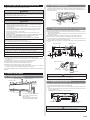
5.1. Installation dimensions
(Wall cap)
1.5 m or over
60 mm or over**
80 mm or over*
Wall hook bracket
130 mm
or over**
1.8 m or over
* The distance between the wall hook
bracket and the ceiling should be
80 mm or more.
** The side next to the sidewall must
IROORZWKHVL]HLQGLFDWHGLQ¿JXUH
]1
5.2. Indoor unit piping direction
7KHSLSLQJFDQEHFRQQHFWHGLQWKHGLUHFWLRQVLQWKH¿JXUH:KHQWKHSLSLQJLVFRQ-
nected in direction (B), (C), (D) or (E), cut along the piping groove in the side of the front
panel with a hacksaw.
(B) Right
outlet
(A) Rear
outlet
(C) Bottom
outlet
(D) Left bottom
outlet
(E) Left
outlet
(Rear)
(F) Centre
outlet
(G) Left rear
outlet
5.3. Cutting the hole in the wall for the connecting pipes
&XWDPPGLDPHWHUKROHLQWKHZDOODWWKHSRVLWLRQVKRZQLQWKH¿JXUH
(2)
When cutting the wall hole at the inside of the wall hook bracket, cut the hole to a point of
intersection of centre marks.
When cutting the wall hole at the outside of the wall hook bracket, cut the hole at a
point of 10 mm below.
(3) Cut the hole so that the outside end is lower (5 to 10 mm) than the inside end.
(4) Always align the centre of the wall hole. If misaligned, water leakage will occur.
(5) Cut the wall pipe to match the wall thickness, stick it into the wall cap, fasten the cap
with vinyl tape, and stick the pipe through the hole.
)RUOHIWSLSLQJ DQG ULJKWSLSLQJFXW WKH KROHDOLWWOH ORZHU VRWKDWGUDLQ ZDWHU ZLOOÀRZ
freely.
Wall hook bracket
Centring marks
LowerLower
10 mm
or more
80 mm hole
10 mm
or more
Fasten with vinyl tape
5~10 mm
Wall pipe
(Field supply)
Wall cap
(Field supply)
(Inside)
(Outside)
Wall
80 mm hole
WARNING
If the wall pipe is not used, the cable interconnecting the indoor unit(s) and outdoor unit
or branch box may touch metal and cause electric discharge.
]1
5.4. Installing the wall hook bracket
(1) Install the wall hook bracket so that it is correctly positioned horizontally and vertically.
,IWKHZDOOKRRNEUDFNHWLVWLOHGZDWHUZLOOGULSWRWKHÀRRU
(2) Install the wall hook bracket so that it is strong enough to support the weight of the
unit.
Ɣ
Fasten the wall hook bracket to the wall with 6 or more screws through the holes near the
outer edge of the bracket
.
Ɣ &KHFNWKDWWKHUHLVQRUDWWOHDWWKHZDOOKRRNEUDFNHW
Wall hook bracket
Tapping screw (large)
(Accessory, 8 pcs)
CAUTION
Install the wall hook bracket by levelling, both horizontally and vertically.

En-4
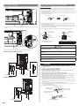
5.5. Forming the drain hose and pipe
CAUTION
Insert drain hose and drain cap securely. Drain should slope down to avoid water
leakage.
When inserting the drain hose, no other material than water should be applied.
Application of other material will cause deterioration of the hose, and may cause water
leakage.
When you remove the drain hose, be sure to attach the drain cap.
When you secure the piping and drain hose with tape, arrange the drain hose so that it
is placed under the piping.
For drain hose piping in low temperature environment, you need to apply protection to
prevent a frozen drain hose.
In low temperature environment (when outdoor temperature is under 0 °C), water in
the drain hose could be frozen after cooling operation. Frozen drain water will block the
ZDWHUÀRZLQWKHKRVHDQGPD\FDXVHZDWHUOHDNDJHDWWKHLQGRRUXQLW
[Rear piping, Right piping, Bottom piping]
,QVWDOOWKHLQGRRUXQLWSLSLQJLQWKHGLUHFWLRQRIWKHZDOOKROHDQGELQGWKHGUDLQKRVHDQG
pipe together with vinyl tape.
,QVWDOOWKHSLSLQJVRWKDWWKHGUDLQKRVHLVDWWKHERWWRP
:UDSWKHSLSHVRIWKHLQGRRUXQLWWKDWDUHYLVLEOHIURPWKHRXWVLGHZLWKGHFRUDWLYHWDSH
Right piping
Bind with vinyl tape
Indoor unit drain hose
(bottom)
Pipe (top)
Rear piping
Bottom piping
[For Left rear piping, Left piping]
Interchange the drain cap and the drain hose.
Drain cap
Indoor unit
drain hose
Remove the drain cap by pull-
ing at the projection at the end
of the cap with pliers, etc.
For left outlet piping, cut
off the piping outlet cutting
groove with a hacksaw.
CAUTION
Insert the drain hose and drain cap into the drain port, making sure that it comes
in contact with the back of the drain port, and then mount it. If the drain hose is not
connected properly, leaking will occur.
)RUOHIWSLSLQJDQGOHIWUHDUSLSLQJDOLJQWKHPDUNVRQWKHZDOOKRRNEUDFNHWDQGVKDSH
the connection pipe.
%HQGWKHFRQQHFWLRQSLSLQJDWWKHEHQGUDGLXVRIPPRUPRUHDQGLQVWDOOQRPRUH
than 35 mm from the wall.
$IWHUSDVVLQJWKHLQGRRUSLSLQJDQGGUDLQKRVHWKURXJKWKHZDOOKROHKDQJWKHLQGRRUXQLW
on the hooks at the top and bottom of the wall hook bracket.
Wall hook
bracket
Alignment marks
Small piping
Connection
piping
Large piping
Top hooks
Indoor
unit
(Fitting)
Bottom hooks
Wall hook
bracket
$IWHU KRRNLQJ WKH LQGRRU XQLW WR WKHWRS KRRN KRRN WKH ¿WWLQJV RI WKH LQGRRU XQLWWR WKH
2 bottom hooks while lowering the unit and pushing it against the wall.
[Installing the indoor unit]
+DQJWKHLQGRRUXQLWIURPWKHKRRNVDWWKHWRS
of the wall hook bracket.
,QVHUWWKHVSDFHUHWFEHWZHHQWKHLQGRRUXQLWDQG
the wall hook bracket and separate the bottom of
the indoor unit from the wall.
5.6. Pipe connection
WARNING
7LJKWHQ WKHÀDUH QXWVZLWK DWRUTXH ZUHQFK XVLQJ WKH VSHFL¿HG WLJKWHQLQJ PHWKRG
2WKHUZLVHWKHÀDUH QXWVFRXOGEUHDNDIWHUDSURORQJHGSHULRGFDXVLQJUHIULJHUDQWWR
OHDNDQGJHQHUDWHKD]DUGRXVJDVLIWKHUHIULJHUDQWFRPHVLQWRFRQWDFWZLWKDÀDPH
5.6.1. Flaring
8VHVSHFLDOSLSHFXWWHUDQGÀDUHWRROH[FOXVLYHIRU5$
(1) Cut the connection pipe to the necessary length with a pipe cutter.
(2) Hold the pipe downward so that cuttings will not enter the pipe and remove any burrs.
,QVHUWWKHÀDUHQXWDOZD\VXVHWKHÀDUHQXWDWWDFKHGWRWKHLQGRRUDQGRXWGRRUXQLWV
UHVSHFWLYHO\RQWRWKHSLSHDQGSHUIRUPWKHÀDUHSURFHVVLQJZLWKDÀDUHWRRO8VHWKH
VSHFLDO5$ÀDUHWRRORUWKHFRQYHQWLRQDOÀDUHWRRO/HDNDJHRIUHIULJHUDQWPD\
UHVXOWLIRWKHUÀDUHQXWVDUHXVHG
(4) Protect the pipes by pinching them or with tape to prevent dust, dirt, or water from
entering the pipes.
B
A
L
&KHFNLI>/@LVÀDUHGXQLIRUPO\
and is not cracked or scratched.
Pipe
Die
Pipe outside
diameter
[mm (in.)]
Dimension A [mm]
Dimension B
0
- 0.4
[mm]
Flare tool for R410A,
clutch type
6.35 (1/4)
0 to 0.5
9.1
9.52 (3/8) 13.2
15.88 (5/8) 19.7
:KHQXVLQJFRQYHQWLRQDOÀDUHWRROVWRÀDUH5$SLSHVWKHGLPHQVLRQ$VKRXOGEH
DSSUR[LPDWHO\PPPRUHWKDQLQGLFDWHGLQWKHWDEOHIRUÀDULQJZLWK5$ÀDUHWRROV
WRDFKLHYHWKHVSHFL¿HGÀDULQJ8VHDWKLFNQHVVJDXJHWRPHDVXUHWKHGLPHQVLRQ$
Width
across
ÀDWV
Pipe outside
diameter [mm (in.)]
:LGWKDFURVVÀDWV
of Flare nut [mm]
6.35 (1/4) 17
9.52 (3/8) 22
15.88 (5/8) 29
5.6.2. Bending pipes
CAUTION
To prevent breaking of the pipe, avoid sharp bends. Bend the pipe with a radius
curvature of 150 mm or more.
If the pipe is bent repeatedly at the same place, it will break.
If pipes are shaped by hand, be careful not to collapse them.
Do not bend the pipes in an angle more than 90°.
When pipes are repeatedly bend or stretched, the material will harden, making it
GLI¿FXOWWREHQGRUVWUHWFKWKHPDQ\PRUH
Do not bend or stretch the pipes more than 3 times.
When bending the pipe, do not bend it
as is. The pipe will be collapsed. In this
case, cut the insulating pipe with a sharp
cutter as shown on the right, and bend
it after exposing the pipe. After bending
the pipe as you want, be sure to put the
heat insulating pipe back on the pipe,
and secure it with tape.
Pipe
Insulating
Pipe
Cutter
Cut line
Indoor unit
Wall hook bracket
(Spacer)

En-5
WARNING
Be sure to perform the earthing (grounding) work.
Do not connect earthing (grounding) wires to a gas pipe, water pipe, lightning rod or
earthing (grounding) wire for a telephone.
&RQQHFWLRQWRDJDVSLSHPD\FDXVHD¿UHRUH[SORVLRQLIJDVOHDNV
Connection to a water pipe is not an effective earthing (grounding) method if PVC
pipe is used.
Connection to the earthing (grounding) wire of a telephone or to a lightning rod may
cause a dangerously abnormal rise in the electrical potential if lightning strikes.
Improper earthing (grounding) work can cause electric shocks.
Securely install the electrical box cover on the unit. An improperly installed service panel
FDQFDXVHVHULRXVDFFLGHQWVVXFKDVHOHFWULFVKRFNRU¿UHWKURXJKH[SRVXUHWRGXVWRU
water.
CAUTION
The primary power supply capacity is for the air conditioner itself, and does not include
the concurrent use of other devices.
Do not start operation until the refrigerant is charged completely. The compressor will
fail if it is operated before the refrigerant piping charging is complete.
Be sure not to remove thermistor sensor etc. from power wiring and connection wiring.
Compressor may fail if operated while removed.
Start wiring work after closing branch switch and over current breaker.
When using an earth leakage breaker that has been designed solely for earth (ground)
fault protection, be sure to install a fuse-equipped switch or circuit breaker.
Do not connect the AC power supply to the transmission line terminal board. Improper
wiring can damage the entire system.
If the temperature surrounding the breaker is too high, the amperage at which the
breaker cuts out may decrease.
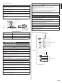
[Heat & Cool model (Reverse cycle)]
3
2
1
4
5
Connection cable
Terminal block
To outdoor unit
[Cooling model]
3
2
1
Connection cable
Terminal block
To outdoor unit
5.6.3. Pipe connection
CAUTION
Be sure to Install the pipe against the port on the indoor unit correctly. If the centring
LVLPSURSHUWKHÀDUHQXWFDQQRWWLJKWHQVPRRWKO\,IWKHÀDUHQXWLVIRUFHGWRWXUQWKH
threads will be damaged.
Do not remove the flare nut from the indoor unit pipe until immediately before
connecting the connection pipe.
Hold the torque wrench at its grip, keeping it in the right angle with the pipe, in order to
WLJKWHQWKHÀDUHQXWFRUUHFWO\
7LJKWHQ WKH ÀDUH QXWV ZLWK D WRUTXH ZUHQFK XVLQJ WKH VSHFL¿HG WLJKWHQLQJ PHWKRG
2WKHUZLVHWKHÀDUH QXWVFRXOGEUHDNDIWHUDSURORQJHGSHULRGFDXVLQJUHIULJHUDQWWR
OHDNDQGJHQHUDWHKD]DUGRXVJDVLIWKHUHIULJHUDQWFRPHVLQWRFRQWDFWZLWKDÀDPH
In order to prevent water from leaking into the control box, make sure that the piping is
well insulated.
Tighten with two wrenches.
:UHQFK¿[HG
Flare nut
Torque wrench
Indoor unit
pipe
Connection pipe
To prevent gas leakage,
FRDWWKHÀDUHVXUIDFH
with refrigerator oil.
Flare nut tightening torque
Flare nut Tightening torque
6.35 mm (1/4 in.) 16 to 18 N · m (160 to 180 kgf · cm)
9.52 mm (3/8 in.) 32 to 42 N · m (320 to 420 kgf · cm)
15.88 mm (5/8 in.) 63 to 75 N · m (630 to 750 kgf · cm)
Do not remove the cap from the connection pipe before connecting the pipe.
6. ELECTRICAL WIRING
]1
6.1. Wiring system diagram
WARNING
Before connecting the wires, make sure the power supply is OFF.
8VHDGHGLFDWHGSRZHUVXSSO\FLUFXLW,QVXI¿FLHQWSRZHUFDSDFLW\LQWKHHOHFWULFDOFLUFXLW
RULPSURSHUZLULQJPD\FDXVHHOHFWULFVKRFNRU¿UH
Install a breaker at the power supply. Improper breaker selection can cause electric
VKRFNRU¿UH
Install a leakage circuit breaker in accordance with the related laws and regulations.
An improperly installed electrical box cover can cause serious accidents such as electric
VKRFNRU¿UHWKURXJKH[SRVXUHWRGXVWRUZDWHU
A circuit breaker is installed in the permanent wiring. Always use a circuit that can trip
all the poles of the wiring and has an isolation distance of at least 3 mm between the
contacts of each pole.
8VHGHVLJQDWHGFDEOHVDQGSRZHUFDEOHV,PSURSHUXVHPD\FDXVHHOHFWULFVKRFNRU¿UH
E\SRRUFRQQHFWLRQLQVXI¿FLHQWLQVXODWLRQRURYHUFXUUHQW
Do not modify power cable, use extension cable or branch wiring. Improper use may
FDXVHHOHFWULFVKRFNRU¿UHE\SRRUFRQQHFWLRQLQVXI¿FLHQWLQVXODWLRQRURYHUFXUUHQW
Connect the connector cable securely to the terminal. Check no mechanical force bears
RQWKHFDEOHVFRQQHFWHGWRWKHWHUPLQDOV)DXOW\LQVWDOODWLRQFDQFDXVHD¿UH
8VHURXQGWHUPLQDOVDQGWLJKWHQWKHWHUPLQDOVFUHZVWRWKHVSHFL¿HGWRUTXHVRWKHUZLVH
abnormal overheating may be produced and possibly cause serious damage inside the
unit.
Make sure to secure the insulation portion of the connector cable with the cable clamp.
Damaged insulation can cause a short circuit.
Fix cables so that cables do not make contact with the pipes (especially on high
pressure side). Do not make power supply cable and transmission cable come in
contact with valves (Gas).
Never install a power factor improvement condenser. Instead of improving the power
factor, the condenser may overheat.

En-6
6.2. Indoor unit wiring
(1) Open the intake grille. Remove the tapping screw for the wire cover and remove the
wire cover.
Screw
Wire cover
(2) Remove the tapping screw and while minding the cable clamp hook, remove the cable
clamp.
Screw
Cable clamp
Cable clamp
Hook
(3) Connect the end of the connection cable fully into the terminal block.
[Heat & Cool model (Reverse cycle)]
25 mm
25 mm
65 mm
Earth (ground) wire
[Cooling model]
123
25 mm
65 mm
Earth (ground) wire
6.3. How to connect wiring to the terminals
Caution when wiring cable
When stripping off the insulation of a lead wire, always use a special tool such as a wire
stripper. If there is no special tool available, carefully strip the insulation with a knife etc.
8VH5LQJWHUPLQDOVZLWKLQVXODWLQJVOHHYHVDVVKRZQLQWKH¿JXUHEHORZWRFRQQHFWWR
the terminal block.
(2) Securely clamp the Ring terminals to the wires using an appropriate tool so that the
wires do not come loose.
Strip : 10 mm
Sleeve
Ring terminal
8VHWKH VSHFL¿HGZLUHV FRQQHFWWKHP VHFXUHO\DQG IDVWHQWKHP VRWKDW WKHUH LV QR
stress placed on the terminals.
(4) Use an appropriate screwdriver to tighten the terminal screws. Do not use a screw-
driver that is too small, otherwise, the screw heads may be damaged and prevent the
screws from being properly tightened.
(5) Do not tighten the terminal screws too much, otherwise, the screws may break.
Wire
Screw with
special washer
Screw with
special washer
Ring
terminal
Ring
terminal
Terminal blocks
Wire
(6) See the table for the terminal
screw tightening torques.
Tightening torque [N·m (kgf·cm)]
M4 screw 1.2 to 1.8 (12 to 18)
CAUTION
Match the terminal block numbers and connection cable colours with those of the
outdoor unit or branch box.
Erroneous wiring may cause burning of the electric parts.
&RQQHFWWKHFRQQHFWLRQ FDEOHV¿UPO\ WRWKH WHUPLQDOEORFN ,PSHUIHFWLQVWDOODWLRQ PD\
FDXVHD¿UH
Always fasten the outside covering of the connection cable with the cable clamp.
(If the insulator is chafed, electric discharge may occur.)
Always connect the earth (ground) wire.
Do not use the earth (ground) screw of the indoor unit for the connection other than a
VSHFL¿HGRXWGRRUXQLWRUEUDQFKER[
]1]1
7. FINISHING
(1) Insulate between pipes. (Varies upon direction of the piping as shown in “5.2. Indoor
unit piping direction”)
Ɣ,QVXODWHVXFWLRQDQGGLVFKDUJHSLSHVVHSDUDWHO\
For (A) Rear, (B) Right, and (C) Bottom piping:
Ɣ2YHUODSWKHFRQQHFWLRQSLSHKHDWLQVXODWLRQDQGLQGRRUXQLWSLSHKHDWLQVXODWLRQDQG
bind them with vinyl tape so that there is no gap.
For (D) Left bottom, (E) Left, (F) Centre and (G) Left rear piping:
Ɣ%XWWWKHFRQQHFWLRQSLSHKHDWLQVXODWLRQDQGLQGRRUXQLWSLSHKHDWLQVXODWLRQWRJHWKHU
and bind them with and vinyl tape so that there is no gap.
Ɣ:UDSWKHDUHDZKLFKDFFRPPRGDWHVWKHUHDUSLSLQJKRXVLQJVHFWLRQZLWKFORWKWDSH
Ɣ%LQGWKHFRQQHFWLRQFDEOHWRWKHWRSRIWKHSLSHZLWKYLQ\OWDSH
Ɣ%XQGOHWKHSLSLQJDQGGUDLQKRVHWRJHWKHUE\ZUDSSLQJWKHPZLWKFORWKWDSHRYHUWKH
UDQJHZLWKLQZKLFKWKH\¿WLQWRWKHUHDUSLSLQJKRXVLQJVHFWLRQ
(2) Temporarily fasten the connection cable along the connection pipe with vinyl tape.
(Wrap to about 1/3 the width of the tape from the bottom of the pipe so that water
does not enter.)
(3) Fasten the connection pipe to the outside wall with saddles, etc.
(4)
Fill the gap between the outside wall pipe hole and the pipe with sealer so that rain
water and wind cannot blow in.
(5) Fasten the drain hose to the outside wall, etc.
Overlap the insulation
Bind the pipes together so
that there is no gap.
Connection pipe
(heat insulation)
Vinyl tape
Indoor unit pipe
(heat insulation)
Wrap with cloth tape
Pipe
Drain hose
Cloth tape

En-7
8.2. Front panel installation
)LUVW ¿WWKH ORZHU SDUW RI WKH IURQW SDQHO DQG LQVHUW WRS DQGPLGGOH KRRNV WRS
sides, 5 middles)
Front panel
Top hooks
(3 position)
Top holes (3 position)
Indoor unit
Middle hooks
(5 position)
Middle hooks
(5 position)
(2) Attach the 10 screws.
(3) Attach the wire cover.
(4) Attach the 4 caps.
(5) Attach the intake grille.
CAUTION
Install the front panel and INTAKE GRILLE securely. If installation is imperfect, the front
panel or INTAKE GRILLE may fall off and cause injury.
9. REMOTE CONTROLLER INSTALLATION
CAUTION
Check that the indoor unit correctly receives the signal from the remote controller, then
install the remote controller holder.
Select the remote controller holder selection site by paying careful attention to the
following:
Avoid places in direct sunlight.
Select a place that will not be affected by the heat from a stove, etc.
9.1. Remote controller holder installation
Install the remote controller a maximum distance of 7 m from the remote control re-
ceiver. However, when installing the remote controller, check that it operates correctly.
,QVWDOOWKHUHPRWHFRQWUROOHUKROGHUWRDZDOOSLOODUHWFZLWKWKHWDSSLQJVFUHZ
remote controller
KROGHU¿[LQJ
Remote
controller holder
Tapping screw
(small)
remote controller
mounting
Remote
controller
2
Slide
1
Set
Example of left piping
Connection
cable
Pipe
Drain hose
Example of left rear piping
Connection cable
Wall pipe
Connection pipe
Drain hose
*Field supply
Pipe
Saddle*
Outside wall cap*
Sealer putty*
(Outdoors)
Wall
Check the following:
GOOD
Lifted up
Saddle
Wave End in water
PROHIBITED
PROHIBITED
PROHIBITED
Drain hose
8. FRONT PANEL REMOVAL AND INSTALLATION
Intake grill removal Intake grill installation
b
a
Open the intake
grille. While gently
pressing the left
and right mounting
shafts of the intake
grille outward “a”,
remove the intake
grille in direction of
the arrow “b”.
c
While holding the
grille horizontal, set
the left and right
mounting shafts into
the pillow blocks at
the top of the panel
“c”.
To latch each shaft
properly, insert the
shaft until it snaps.
Press 4 places on
the intake grille to
close it completely.
8.1. Front panel removal
(1) Remove intake grille (Reference the intake grille removal.)
(2) Remove 4 caps.
(3) Remove wire cover.
(4) Remove 10 screws.
Screws (Wire cover)
Screws (10 position)
Caps (4 position)
Wire cover
NOTE : When replacing the front panel, do not scratch or damage the louver.
(5) The front panel is pulled to the front, raising the upper surface, then the front panel is
removed.
Front panel

En-8
10. OPTIONAL KIT INSTALLATION
This air conditioner can be connected with the following optional kits.
:LUHGUHPRWHFRQWUROOHU
([WHUQDOFRQQHFWNLW
11. FUNCTION SETTING
Perform the “FUNCTION SETTING” according to the installation conditions using the
remote controller.
CAUTION
&RQ¿UPZKHWKHUWKHZLULQJZRUNIRU2XWGRRUXQLWRU%UDQFKER[KDVEHHQ¿QLVKHG
&RQ¿UPWKDWWKHFRYHUIRUWKHHOHFWULFDOHQFORVXUHRQWKHRXWGRRUXQLWLVLQSODFH
7KLVSURFHGXUHFKDQJHVWRWKHIXQFWLRQVHWWLQJVXVHGWRFRQWUROWKHLQGRRUXQLW
according to the installation conditions. Incorrect settings can cause the indoor unit to
malfunction.
$IWHU WKH SRZHU LVWXUQHGRQ SHUIRUP WKH ³)81&7,216(77,1*´DFFRUGLQJ WR WKH
installation conditions using the remote controller.
7KHVHWWLQJVPD\EHVHOHFWHGEHWZHHQWKHIROORZLQJWZR)XQFWLRQ1XPEHUDQG6HWWLQJ
Value.
6HWWLQJVZLOOQRWEHFKDQJHGLILQYDOLGQXPEHUVRUVHWWLQJYDOXHVDUHVHOHFWHG
5HIHUWR WKHLQVWDOODWLRQ PDQXDOHQFORVHG ZLWKWKH UHPRWHFRQWUROOHU ZKHQWKH ZLUHG
remote controller (option) is used.
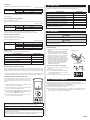
Entering the Function Setting Mode
While pressing the POWERFUL COOLING button and MODE button simultaneously,
press the RESET button to enter the function setting mode.
STEP 1
Selecting the Remote Controller Custom Code
Use the following steps to select the custom code of the
remote controller. (Note that the air conditioner cannot
receive a signal if the air conditioner has not been set for
the custom code.)
The custom codes that are set through this process are ap-
plicable only during the FUNCTION SETTING process. For
details on how to set the custom codes through the normal
process, refer to “Remote controller custom code setting”.
(1)
Press TEMP. ( ) ( ) buttons to change the custom
FRGHEHWZHHQ$ĺ%ĺ&ĺ'0DWFKWKHFRGHRQWKH
display to the air conditioner custom code (initially set
to A). (If the custom code does not need to be selected,
press the MODE button and proceed to STEP 2.)
(2)
Press the START/STOP button and check that the indoor
unit can receive signals at the displayed custom code.
(3)
Press the MODE button to accept the custom code, and
proceed to STEP 2.
STEP 2
Selecting the Function Number and Setting Value
(1)
Press the TEMP. ( ) ( ) buttons to select the function number. (Press the FAN (-)
button to switch between the left and right digits.)
(2)
Press the FAN (+) button to proceed to setting the
value. (Press the FAN (+) button again to return to
the function number selection.)
(3)
Press the TEMP. ( ) ( ) buttons to select the
setting value. (Press the FAN (-) button to switch
between the left and right digits.)
(4)
Press the START/STOP button, then the POWER-
)8/&22/,1*EXWWRQLQRUGHUWR¿[WKHVHWWLQJV
(5)
Press the RESET button to end the function set-
ting mode.
(6)
After completing the FUNCTION SETTING, be
sure to turn off the power and turn it on again.
CAUTION
After turning off the power, wait 30 seconds or more before turning on it again.
The Function Setting does not become active unless the power is turned off then on
again.
Room temperature sensor control for cooling
Depending on the installed environment, correction of the room temperature sensor may
be required. Select the appropriate control setting according to the installed environment.
(
¡
... Factory setting)
Function number Setting value
Setting description
30
00 Standard
¡
01 Lower control
Room temperature sensor control for heating
Depending on the installed environment, correction of the room temperature sensor may
be required. Select the appropriate control setting according to the installed environment.
(
¡
... Factory setting)
Function number Setting value
Setting description
31
00 Standard
¡
01 Lowest control
02 Lower control
03 Low control
Function number
Setting
value

En-9
Auto restart
Enable or disable automatic restart after a power interruption.
(
¡
... Factory setting)
Function number Setting value
Setting description
40
00 Enable
¡
01 Disable
* Auto restart is an emergency function such as for power outage etc. Do not attempt to
use this function in normal operation. Be sure to operate the unit by remote controller or
external device.
Room temperature sensor switching
(Only for wired remote controller)
When using the Wired remote controller temperature sensor, change the setting to “Both”
(01).
(
¡
... Factory setting)
Function number Setting value
Setting description
42
00 Indoor unit
¡
01 Both
00: Sensor on the indoor unit is active.
01: Sensors on both indoor unit and wired remote controller are active.
* Remote controller sensor must be turned on by using the remote controller
Remote controller custom code
(Only for wireless remote controller)
The indoor unit custom code can be changed.
Select the appropriate custom code.
(
¡
... Factory setting)
Function number Setting value
Setting description
44
00 A
¡
01 B
02 C
03 D
Setting record
Record any changes to the settings in the following table.
Function setting Setting Value
Room temperature sensor control for cooling
Room temperature sensor control for heating
Auto restart
Room temperature sensor switching
Remote controller custom code
After completing the Function Setting, be sure to turn off the power and turn it on again.
Remote controller custom code setting
When 2 or more air conditioners are installed in a room and the remote controller is oper-
ating an air conditioner other than the one you wish to set, change the custom code of the
remote controller to operate only the air conditioner you wish to set (4 selections possible).
&RQ¿UPWKHVHWWLQJRIWKHUHPRWHFRQWUROOHUFXVWRPFRGHDQGWKHIXQFWLRQVHWWLQJ,IWKHVH
do not match, the remote controller cannot be used to operate for the air conditioner.
Selecting the Remote Controller Custom Code
Use the following steps to select the custom code of the re-
mote controller. (Note that the air conditioner cannot receive
a signal if the air conditioner has not been set for the custom
code.)
(1) Press the START/STOP button until only the clock is dis-
played on the remote controller display.
(2) Press the MODE button for at least 5 seconds to display
the current custom code (initially set to A).
(3) Press SET TEMP. (
) ( ) buttons to change the cus-
WRPFRGH EHWZHHQ$ĺ%ĺ&ĺ' 0DWFKWKH FRGHRQ WKH
display to the air conditioner custom code.
(4) Press the MODE button again to return to the clock dis-
play. The custom code will be changed.
If no buttons are pressed within 30 seconds after the custom code is displayed, the sys-
tem returns to the original clock display. In this case, start again from step 1.
The air conditioner custom code is set to A prior to shipment.
The remote controller resets to custom code A when the batteries in the remote control-
ler are replaced. If you use a custom code other than custom code A, reset the custom
code after replacing the batteries.
If you do not know the air conditioner custom code setting, try each of the custom codes
$ĺ%ĺ&ĺ'XQWLO\RX¿QGWKHFRGHZKLFKRSHUDWHVWKHDLUFRQGLWLRQHU
12. CHECK LIST
Pay special attention to the check items below when installing the indoor unit(s). After
installation is complete, be sure to check the following check items again.
CHECK ITEMS CHECK BOX
Has the indoor unit been installed correctly?
Has there been a check for gas leaks (refrigerant pipes)?
Has heat insulation work been completed?
Does water drain easily from the indoor units?
Are the wires and pipes all connected completely?
,VWKHFRQQHFWLRQFDEOHWKHVSHFL¿HGWKLFNQHVV"
Are the inlets and outlets free of any obstacles?
After installation is completed, has the proper operation and
handling been explained to the user?
13. TEST RUN
WARNING
Do not turn on the power until all installation work is complete.
CAUTION
When restarting after a long period of disuse in the winter, turn the power switch on at least
12 hours before starting the unit.
Do not operate the air conditioner in test run for a long time.
[Operation method]
Ɣ)RUWKHRSHUDWLRQPHWKRGUHIHUWRWKHRSHUDWLQJ
manual.
Ɣ7KHRXWGRRUXQLWPD\QRWRSHUDWHGHSHQGLQJ
on the room temperature. In this case, press
the TEST RUN button on the remote controller
while the air conditioner is running. (Point the
transmitter section of the remote controller
toward the air conditioner and press the TEST
RUN button with the tip of a ballpoint pen, etc.)
Ɣ7RHQGWHVWRSHUDWLRQSUHVVWKHUHPRWHFRQWUROOHU
START/STOP button. (When the air conditioner
is running by pressing the TEST RUN button, the
OPERATION Lamp and TIMER Lamp will
VLPXOWDQHRXVO\ÀDVKVORZO\
[Using the wired remote control] (Option)
Ɣ
For the operation method, refer to the operating
manual.
(1) Stop the air conditioner operation.
(2) Press the master control button and the FAN
control button simultaneously for 2 seconds or
more to start the test run.
(3) Press the START/STOP button to stop the test run.
14. CUSTOMER GUIDANCE
Explain the following to the customer in accordance with the operating manual:
(1) Starting and stopping method, operation switching, temperature adjustment, timer, air
ÀRZVZLWFKLQJDQGRWKHUUHPRWHFRQWUROXQLWRSHUDWLRQV
$LU¿OWHUUHPRYDODQGFOHDQLQJDQGKRZWRXVHWKHDLUORXYHUV
(3) Give the operating manual to the customer.
(4) If the custom code is changed, explain to the customer how it changed (the system
returns to custom code A when the batteries in the remote controller are replaced).
*(4) is applicable to using wireless remote controller.
Test run display
Transmitter section
TEST RUN button

En-10
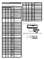
15. ERROR CODES
If you use a wireless remote controller, the lamp on the photo detector unit will output er-
ror codes by way of blinking patterns. If you use a wired remote controller, error codes will
appear on the remote controller display. See the lamp blinking patterns and error codes in
the table. An error display is displayed only during operation.
Error display
Wired
remote
controller
Error code
Description
OPERATION
lamp
(green)
TIMER
lamp
(orange)
POWERFUL
lamp
(green)
Ɣ
(1)
Ɣ
(1)
¸
Serial communication error
Ɣ
(1)
Ɣ
(2)
¸
Wired remote controller
communication error
Ɣ
(1)
Ɣ
(5)
¸
&KHFNUXQXQ¿QLVKHG
Ɣ
(2)
Ɣ
(1)
¸
Unit number or Refrigerant circuit
address setting error
[Simultaneous Multi]
Ɣ
(2)
Ɣ
(2)
¸
Indoor unit capacity error
Ɣ
(2)
Ɣ
(3)
¸
Combination error
Ɣ
(2)
Ɣ
(4)
¸
Connection unit number
error (indoor slave unit)
[Simultaneous Multi]
Connection unit number error
(indoor unit or branch unit)
[Flexible Multi]
Ɣ
(2)
Ɣ
(7)
¸
Master unit, slave unit set-up
error [Simultaneous Multi]
Ɣ
(3)
Ɣ
(2)
¸
Indoor unit PCB model
information error
Ɣ
(3)
Ɣ
(5)
¸
Manual auto switch error
Ɣ
(4)
Ɣ
(1)
¸
Room temp. sensor error
Ɣ
(4)
Ɣ
(2)
¸
Indoor unit Heat Ex. Middle temp.
sensor error
Ɣ
(5)
Ɣ
(1)
¸
Indoor unit fan motor error
Ɣ
(5)
Ɣ
(3)
¸
Drain pump error
Ɣ
(5)
Ɣ
(7)
¸
Damper error
Ɣ
(5)
Ɣ
(15)
¸
Indoor unit error
Ɣ
(6)
Ɣ
(2)
¸
Outdoor unit main PCB model
information error or
communication error
Ɣ
(6)
Ɣ
(3)
¸
Inverter error
Ɣ
(6)
Ɣ
(4)
¸
$FWLYH¿OWHUHUURU3)&FLUFXLW
error
Ɣ
(6)
Ɣ
(5)
¸
Trip terminal L error
Ɣ
(6)
Ɣ
(8)
¸
Outdoor unit rush current limiting
resister temp. rise error
Ɣ
(6)
Ɣ
(10)
¸
Display PCB microcomputers
communication error
Ɣ
(7)
Ɣ
(1)
¸
Discharge temp. sensor error
Ɣ
(7)
Ɣ
(2)
¸
Compressor temp. sensor error
Ɣ
(7)
Ɣ
(3)
¸
Outdoor unit Heat Ex. liquid
temp. sensor error
Ɣ
(7)
Ɣ
(4)
¸
Outdoor temp. sensor error
Ɣ
(7)
Ɣ
(5)
¸
Suction Gas temp. sensor error
Ɣ
(7)
Ɣ
(6)
¸
2-way valve temp. sensor error
3-way valve temp. sensor error
Ɣ
(7)
Ɣ
(7)
¸
Heat sink temp. sensor error
Ɣ
(8)
Ɣ
(2)
¸
Sub-cool Heat Ex. gas inlet
temp. sensor error
Sub-cool Heat Ex. gas outlet
temp. sensor error
Ɣ
(8)
Ɣ
(3)
¸
Liquid pipe temp. sensor error
Ɣ
(8)
Ɣ
(4)
¸
Current sensor error
Ɣ
(8)
Ɣ
(6)
¸
Discharge pressure sensor
error
Suction pressure sensor error
High pressure switch error
Ɣ
(9)
Ɣ
(4)
¸
Trip detection
Ɣ
(9)
Ɣ
(5)
¸
Compressor rotor position
detection error (permanent stop)
Ɣ
(9)
Ɣ
(7)
¸
Outdoor unit fan motor error
Ɣ
(9)
Ɣ
(9)
¸
4-way valve error
Ɣ
(10)
Ɣ
(1)
¸
Discharge temp. error
Ɣ
(10)
Ɣ
(3)
¸
Compressor temp. error
Ɣ
(10)
Ɣ
(4)
¸
High pressure error
Ɣ
(10)
Ɣ
(5)
¸
Low pressure error
Ɣ
(13)
Ɣ
(2)
¸
Branch boxes error
[Flexible Multi]
Display mode
Ɣ
: 0.5s ON / 0.5s OFF
¸
: 0.1s ON / 0.1s OFF
1XPEHURIÀDVKLQJ
[Troubleshooting with the indoor unit display]
OPERATION indicator (green)
TIMER indicator (orange)
POWERFUL indicator (green)
[Troubleshooting with the Wired Remote Controller Display (Option)]
If an error occurs, the following display will be shown. (“Er” will appear in the set room
temperature display.)
Error code


-
 1
1
-
 2
2
-
 3
3
-
 4
4
-
 5
5
-
 6
6
-
 7
7
-
 8
8
-
 9
9
-
 10
10
-
 11
11
-
 12
12


Fujitsu ASGA18FUTC-B Guide d'installation
- Catégorie
- Climatiseurs split-system
- Taper
- Guide d'installation
- Ce manuel convient également à
dans d''autres langues
Documents connexes
Autres documents
-
 Mitsubishi Electronics MSZ-FD09/12NA Manuel utilisateur
-
LG URNU36GVKA2.ANWALAT Manuel utilisateur
-
-
York Water Source Heat Pump and Heat Recovery Outdoor Units 208-460V Guide d'installation
-
Toshiba RAS-M05G3KVSG-E Manuel utilisateur
-
Mitsubishi Electric VG79J799H01 Manuel utilisateur
-
Mitsubishi Electric MSZ-GS18NA-U1 GS-Series 18k BTU Wall Mounted Unit Manuel utilisateur
-
Haier AC60FS1ERA Manuel utilisateur
-
Impecca ISAH-1220A1S Manuel utilisateur
-
Panasonic CS-E24RKUAW Guide d'installation
