FSR RGB-144 Manuel utilisateur
- Catégorie
- Amplificateurs de ligne vidéo
- Taper
- Manuel utilisateur

LIT1002
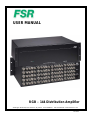
USER MANUAL
RGB – 144 Distribution Amplifier
244 Bergen Boulevard, West Paterson, NJ 07424 Tel 9737854347 FAX 9737853318 Web www.fsrinc.com

LIT1002
PROPRIETARY INFORMATION
All information in this manual is proprietary to and the property of FSR inc.
This publication is protected by the Federal Copyright Law, with all
rights reserved. No part of this document may be reproduced, transcribed, or
transmitted, in any form or by any means, without prior explicit
written permission from FSR inc.

LIT1002
Operators Safety Summary
The general safety information in this summary is for operating personnel.
Do Not Remove Covers or Panels There are no user-serviceable parts within the unit. Removal of the top cover will expose dangerous voltages.
To avoid personal injury, do not remove the top cover. Do not operate the unit without the cover installed.
Power Source This product is intended to operate from a power source that will not apply more than 230 volts rms between the supply conductors
or between both supply conductor and ground. A protective ground connection by way of grounding conductor in the power cord is essential for safe
operation.
Grounding the Product This product is grounded through the grounding conductor of the power cord. To avoid electrical shock, plug the power
cord into a properly wired receptacle before connecting to the product input or output terminals. A protective-ground connection by way of the
grounding conductor in the power cord is essential for safe operation.
Use the Proper Power Cord Use only the power cord and connector specified for your product. Use only a power cord that is in good condition.
Refer cord and connector changes to qualified service personnel.
Use the Proper Fuse To avoid fire hazard, use only the fuse having identical type, voltage rating, and current rating characteristics. Refer fuse
replacement to qualified service personnel.
Do Not Operate in Explosive Atmospheres To avoid explosion, do not operate this product in an explosive atmosphere.
Terms In This Manual
WARNING Highlights an operating procedure, practice, condition, statement, etc., which, if not strictly observed, could result in injury to or death of
personnel. NOTE Highlights an essential operating procedure, condition or statement.
CAUTION The exclamation point within an equilateral triangle is intended to alert the user to the presence of important operating and
maintenance (servicing) instructions in the literatureaccompanying the appliance.
AVERTISSEMENT! Le point d´exclamation dans un triangle equilatéral signale à alerter l´utilisateur qu´il y a des instructions d´operation et d´entretien
tres importantes dans la litérature qui accompagne l´appareil.
VORSICHT ein Ausrufungszeichen innerhalb eines gleichwinkeligen Dreiecks dient dazu,den Benutzer auf wichtige Bedienungs-und
Wartungsanweisungen in der Dem Great beiliegenden Literatur aufmerksam zu machen.
WARNING The rear panel ON/OFF switch does not disconnect the unit from input AC power. To facilitate disconnection of AC power, the power cord
must be connected to an accessible outlet near the unit. Building Branch Circuit Protection: For 115 V use 20 A, for 230 V use 8 A.
WARNING When the RGB-144 is used in the 230-volt mode, a UL listed line cord rated for 250 volts at 15 amps must be used and must conform to
IEC-227 and IEC-245 standards. This cord will be fitted with a tandem prong-type plug.
TERMS AS MARKED ON EQUIPMENT
CAUTION Highlights an operating procedure, practice, condition, statement, etc., which, if not strictly observed, could result in injury to or death of
personnel.
CAUTION The exclamation point within an equilateral triangle is intended to alert the user to the presence of important operating and
maintenance (servicing) instructions in the literatureaccompanying the appliance.
AVERTISSEMENT! Le point d´exclamation dans un triangle equilatéral signale à alerter l´utilisateur qu´il y a des instructions d´operation et
d´entretien tres importantes dans la litérature qui accompagne l´appareil
VORSICHT Ein Ausrufungszeichen innerhalb eines gleichwinkeligen Dreiecks dient dazu, den Benutzer auf wichtige Bedienungs-und
Wartungsanweisungen in der Dem Great beiliegenden Literatur aufmerksam zu machen.
NOTE This equipment has been tested and found to comply with the limits for a Class A digital device, pursuant to Part 15 of the FCC Rules. These
limits are designed to provide reasonable protection against harmful interference when the equipment is operated in a commercial environment. This
equipment generates, uses, and can radiate radio frequency energy and, if not installed and used in accordance with the instruction manual, may
cause harmful interference to radio communications. Operation of this equipment in a residential area is likely to cause harmful interference, in which
case the user will be required to correct the interference at the users own expense.

LIT1002
INTRODUCTION
The RGB - 144 is the world’s first configurable Distribution Amplifier (D/A). Four independent 1 x 4 D/A’s
are integrated within the 3RU chassis. What makes the RGB-144 unique is the ability to bridge adjacent
1x4 blocks to make a larger D/A.
In it’s default configuration, the RGB-144’s four 1x4 D/A’s operate independently. By simply flipping the
bridge switches, adjacent 1x4 D/A’s are bridged together and the input of the first block is sent to all of the
bridged outputs allowing many different configurations to suit your signal distribution needs.
Possible configurations include: four 1x4 D/A’s; one 1x8, and two 1 x 4 D/A’s; two 1x8 D/A’s; one 1x12,
and one 1x4 D/A’s; and one 1x16 D/A. To insure the highest possible signal quality, all outputs are fully
buffered, and the measured bandwidth, from input to any output, is greater than 350MHz with a flat signal
response.
The RGB-144’s universal sync inputs support both analog and TTL level sync of either polarity. Advanced
sync detection circuitry accurately slices the input sync signal independent of amplitude and offset to
provide a stable, jitter-free output even in noisy environments.
The RGB-144’s extended bandwidth makes it compatible with all computer video resolutions from
workstations, PC’s, notebooks, or Mac’s as well as scalers and line doublers. In addition, each of the
RGB inputs may be used independently or in concert to distribute composite, component, and S-video. A
universal power supply extends the RGB-144 s compatibility to the world.
FEATURES
400 MHz video bandwidth All metal enclosure
Four bridgeable 1x4 D/A Blocks Blocks Rack mount ears included
All outputs are fully buffered Universal worldwide power supply
APPLICATIONS
Boardrooms
Live Event Productions
Education
Conferences Centers
Rental Companies
Video Conferencing,
and other complex Integration Systems not requiring a matrix switcher

LIT1002
TECHNICAL SPECIFICATIONS
400 MHz video bandwidth All metal enclosure
Four bridgeable 1x4 D/A Blocks Blocks Rack mount ears included
All outputs are fully buffered Universal worldwide power supply
Video
Gain: Unity (into 75 ohm load)
Bandwidth: >400MHz (+0.1db/-3db) measured from input connector to output connector
within a block, all outputs connected.
+0.1db/-0.5db 175MHz measured from input connector to output
connector within a block, all outputs connected.
>350MHz (+0.1db /-3db) measured from input to any output connector when
fully bridged , all outputs connected.
+0.1db/-0.5db 150MHz measured from input connector to output
connector when fully bridged, all outputs connected.
Differential Phase Error: 0.04 degrees (NTSC)
Differential Gain Error: 0.04 % (NTSC)
Video Input – Each Block (4 blocks total)
Number/Signal Type: 1 RGBHV, RGBS, RGsB, RsBsGs, component video, composite video, S-video
Connectors: 5 BNC Female
Video Level: ±1.0Vp-p (nominal); 2.0Vp-p (maximum)
Impedance: 75 ohm
Maximum DC offset: ±1.2V (with 0.7Vp-p signal)
Video Output – Each Block (4 blocks total)
Number/Signal Type: 4 Matching input type
Connectors: 5 BNC per output (20 total)
Video Level: ±1.0Vp-p (nominal); 2.0Vp-p (maximum)
Impedance: 75 ohm
Maximum DC offset: ±20MV max
H&V Sync Inputs:
Type: TTL or Analog sync positive or negative polarity (universal sync input)
Level: 0.7 - 5Vp-p; Sync on green 0.3V
Frequency: 50 Hz - 150 KHz on either sync channel
Impedance: 75 ohm
Max Rise/Fall Time: No limit on input rise/fall time due to advanced sync detection circuitry
H&V Sync Outputs:
Level: TTL sync, 2.0Vp-p into 75 ohm load
Rise/Fall Time: 900ps into 75 ohm load
Max propagation delay: 15 ns (each block)
Output Impedance: 75 ohm
GENERAL
Power AC input: 110/220 VAC, 50/60 Hz
Mounting: Table top or rack mount, rack ears included
Enclosure Type/Size: Metal, 3 RU high,19” wide

LIT1002
CONNECTING THE UNIT
DESCRIPTION OF INPUTS AND OUTPUTS
All video input and output connections are BNC female chassis mount connectors. They will accept a
variety of video input types. The power cord entry accepts the supplied IEC power cordset at 110/220
VAC 50/60 Hz. Typical configuration options are illustrated on the following pages.
Video Input Connections
The video input section on the RGB-144 rear panel provides up to four universal inputs. Each input can
accept composite (NTSC/PAL), s-video, component (RGB, Betacam (Y, Pb, Pr)), and computer video
signals. The connections for each input channel are made via five BNC connectors. Connection points for
each type of video signal are specified below.
Format – RGB
(Typical Devices: Computers) Format – YUV or Y Pr Pb (Betacam)
(Typical Devices: DVD Player or Betacam Deck)
Source RGB-144 Source RGB-144
R R/CR Y G/Y
G G/Y Pr R/CR
B B/CB Pb B/CB
H H/C or
V V Y G/Y
U R/CR
Format – S-Video (Y/C)
(Typical Devices: S-Video VCR) V B/CB
Source RGB-144 Format – Composite/PAL (Typical Devices: NTSC/PAL VCR,
VIDEO CAMERA)
Y ANY R, G, or B
INPUT Source RGB-144
C ANY R, G, or B
INPUT NTSC/PAL ANY R, G, or B INPUT
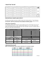
CONFIGURATION CHART
(Matrix showing quantity of input x output combinations for 16 maximum outputs)

LIT1002
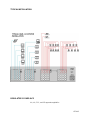
TYPICAL INSTALLATION
REGULATORY COMPLIACE
UL, cUL, FCC, and CE approvals applied for.

LIT1002
LIMITED WARRANTY
The RGB – 144 Distribution Amplifier is warranted against failures due to defective parts or faulty
workmanship for a period of three years after delivery to the original owner. During this period, FSR will
make any necessary repairs or replace the unit without charge for parts or labor. Shipping charges to the
factory or repair station must be prepaid by the owner, return-shipping charges (via UPS Ground) will be
paid by FSR.
This warranty applies only to the original owner and is not transferable. In addition, it does not apply to
repairs done by other than the FSR factory or Authorized Repair Stations.
This warranty shall be cancelable by FSR at its sole discretion if the unit has been subjected to physical
abuse or has been modified in any way without written authorization from FSR. FSR’s liability under this
warranty is limited to repair or replacement of the defective unit.
FSR will not be responsible for incidental or consequential damages resulting from the use or misuse of
its products. Some states do not allow the exclusion of incidental or consequential damages, so the
above limitations may not apply to you. This warranty gives you specific legal rights, and you may also
have other rights which vary from state to state.
Warranty claims should be accompanied by a copy of the original purchase invoice showing the purchase
date (if a Warranty Registration Card was mailed in at the time of purchase, this is not necessary). Before
returning any equipment for repair, please read the important information on service below.
SERVICE
Before returning any equipment for repair, please be sure that it is adequately packed and cushioned
against damage in shipment, and that it is insured. We suggest that you save the original packaging and
use it to ship the product for servicing. Also, please enclose a note giving your name, address, phone
number and a description of the problem.
NOTE: all equipment being returned for repair must have a Return authorization (RMA) Number.
To get a RMA Number, please call the FSR Service Department (1-800-332-FSR1). Please display
your RMA Number prominently on the front of all packages.
CONTACT INFORMATION
244 Bergen Blvd.
West Paterson, NJ 07424
Phone: (973) 785-4347
*Order Desk Fax: (973) 785-4207
E-mail: [email protected]
Web Site: http://www.fsrinc.com
Issue date: 08/02
-
 1
1
-
 2
2
-
 3
3
-
 4
4
-
 5
5
-
 6
6
-
 7
7
-
 8
8


FSR RGB-144 Manuel utilisateur
- Catégorie
- Amplificateurs de ligne vidéo
- Taper
- Manuel utilisateur
dans d''autres langues
- English: FSR RGB-144 User manual
Documents connexes
Autres documents
-
AJA R5CE Manuel utilisateur
-
Sony Ericsson PVM-20M4A Manuel utilisateur
-
AJA HD10A-Plus Installation and Operation Guide
-
GRASS VALLEY Dual Channel UHD Linear Frame Rate Converter Manuel utilisateur
-
Sony VPH-D50QM Manuel utilisateur
-
Analog way OCTO-FADE Manuel utilisateur
-
-
-
AJA HD10MD4 Manuel utilisateur