PR electronics 7501 Series Guide d'installation
- Taper
- Guide d'installation

PR electronics A/S
Lerbakken 10
DK-8410 Rønde
Tel. +45 8637 2677
Fax +45 8637 3085
www.prelectronics.com
}
1
2
File Product Input Output Communication Language Option 08:30:00
PRetop 5331
Date:1994-8-10
943201594
PRelectronics
Analog inputAnalog output
Serial no:
Input type:Output type:4 - 20mA
Upscale
Sensor error:
Pt100 DIN/IEC
0.00 - 50.00 C
3-wire
1.00 sec
------
Input range:
Connection:
Cold junction comp:
Response time:
Tag no:
7501
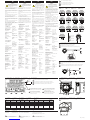
+Vsupply
Input
Receiving
equipment
HART modem
250 Ω <Rload<1100 Ω
}
1
2
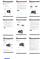
7501
Safe area
+Vsupply
Input
Receiving
equipment
area
250 Ω <Rload<1100 Ω
DK UK FR DE
SN7501_102 (1540)
Mekaniske specifikationer Mechanical specifications Dimensions mécaniques
Abmessungen
DK UK FR
DE
7501 - Installationsvejledning for teknikere.
7501 - Installation guide for technical personnel.
7501 - Guide d’installation pour le personnel qualifié.
7501 Installationsanleitung für Techniker.
UK
DK
FR
DE
ADVARSEL
Modulet må kun tilsluttes af kvalifice-
rede teknikere, som er bekendte med
de tekniske udtryk, advarsler og in-
struktioner i installationsvejledningen,
og som vil følge disse.
Hvis der er tvivl om modulets rette håndtering, skal
der rettes henvendelse til den lokale forhandler eller
alternativt direkte til PR electronics A/S.
Installation og tilslutning af modulet skal følge lan-
dets gældende regler for installation af elektrisk
materiel.
Reparation af modulet må kun foretages af PR elec-
tronics A/S.
Transmitterdækslet må ikke ernes i eksplosionsfar-
ligt område, når kredsløbet er strømførende.
Transmitterdækslet skal være helt lukket for at over-
holde kravene til eksplosionssikring.
Hvis transmitteren er installeret i områder med kraf-
tige vibrationer, kan det være nødvendigt med ekstra
befæstning.
Ved installation i eksplosionsfarligt område skal den
tilhørende installationstegning følges nøje.
Vær opmærksom på ikke at frembringe mekaniske
gnister, når instrumentet og tilhørende enheder til-
gås i eksplosionsfarligt område.
Elektriske specifikationer
Anvendelsestemperatur
med silikone O-ring.............. -40°C til +85°C
med FKM O-ring .................... -20°C til +85°
Reduceret LCD-ydeevne under -20°C og over
+70 °C
Opbevaringstemperatur ........ -40°C til +85°C
Kalibreringstemperatur ......... 20...28°C
Relativ luftfugtighed.............. 0...100% RF (kond.)
Kapslingsklasse ........................ IP54 / IP66 / IP68
type 4X
Mekaniske specifikationer
Diameter ...................................... Ø 110 mm
Mål, H x B x D ............................ 109x145x125,5 mm
Vægt, ca. ...................................... 1,3 kg
Ledningskvadrat ....................... 0,13...1,5 mm2 / AWG
26...16 flerkoret ledning
Klemskruetilspændings-
moment ........................................ 0,4 Nm
Vibration ...................................... IEC 60068-2-6 : 2007
2...25 Hz ................................... ±1,6 mm
25...100 Hz ............................. ±4 g
Fælles specifikationer:
Forsyningsspænding, DC
Ex: ia, egensikker ................. 10...30 VDC
(12...30 VDC med bag-
grundsbelysning)
Øvrige ....................................... 10...35 VDC
(12...35 VDC med bag-
grundsbelysning)
Isolationsspænd., test/oper. . 1,5 kVAC / 50 VAC
Langtidsstabilitet..................... 0,1% af span / år
Indgangsspecifikationer:
Indgang for RTD-typer:
Pt50, Pt100, Pt200, Pt500, Pt1000, Ni50, Ni100,
Ni120, Ni1000
Kabelmodstand pr.
leder (max.) ................................ 5 Ω
Følerstrøm ................................... Nom. 0,2 mA
Indgang for TC-typer:
B, E, J, K, L, N, R, S, T, U, W3, W5, Lr
mV-indgang:
Måleområde, spænding ......... -800...+800 mV
Min. span ..................................... 2,5 mV
Indgangsmodstand ................. 10 MΩ
Strømudgang:
Signalområde ............................. 4...20 mA
Min. signalområde .................... 16 mA
Belastningsmodstand ............ ≤ (Vforsyn. - 10) /
0,023 [Ω]
med baggrundsbelysning . ≤ (Vforsyn. - 12) /
0,023 [Ω]
Følerfejlsdetektering,
programmerbar ......................... 3,5...23 mA
NAMUR NE43 Upscale ........... 23 mA
NAMUR NE43 Downscale ..... 3,5 mA
HART-protolkolrevisioner...... HART 7 og HART 5
Direktiver:
EMC ................................................ 2004/108/EF
ATE X .............................................. 94/9/EF
EAC TR-CU 020/2011 ............ EN 61326-1
RoHS ............................................. 2011/65/EU
WARNING
Only technicians, who are familiar with
the technical terms, warnings, and
instructions in the manual and who are
able to follow these, should connect
the device.
Should there be any doubt as to the correct handling
of the device, please contact your local distributor or
PR electronics A/S.
Mounting and connection of the device should
comply with national legislation for mounting of
electric materials.
Repair of the device must be done by PR electronics
A/S only.
Do not remove the transmitter cover in explosive
atmospheres when the circuit is alive.
The transmitter cover must be fully engaged to meet
the explosion proof requirements.
If installed under high-vibration conditions, the
transmitter may require supplementary support.
For installation in hazardous area the corresponding
installation drawing must be followed in detail.
Take care not to generate mechanical sparking when
accessing the instrument and peripheral devices in a
hazardous location.
Electrical specifications
Operating tempeature
with silicone O-ring ............. -40°C to +85°C
with FKM O-ring .................... -20°C to +85°C
Reduced LCD performance below -20°C
and above +70°C
Storage temperature .............. -40°C to +85°C
Calibration temperature ........ 20...28°C
Relative humidity..................... 0...100% RH (cond.)
Protection degree .................... IP54 / IP66 / IP68
type 4X
Mechanical specifications:
Dimensions ................................ Ø 110 mm
Dimensions, H x W x D .......... 109x145x125.5 mm
Weight approx. .......................... 1.3 kg
Wire size ...................................... 0.13...1.5 mm2 / AWG
26...16 stranded wire
Screw terminal torque ........... 0.4 Nm
Vibration ...................................... IEC 60068-2-6 : 2007
2...25 Hz ................................... ±1.6 mm
25...100 Hz ............................. ±4 g
Common electrical specifications:
Supply voltage, DC:
Ex ia, intrinsically safe ....... 10...30 VDC
(12...30 VDC with
backlight)
Other ......................................... 10...35 VDC
(12...35 VDC with
backlight)
Isolation - test / working ...... 1.5 kVAC / 50 VAC
Long term stability .................. 0.1% of span / year
Input specifications:
RTD input types:
Pt50, Pt100, Pt200, Pt500, Pt1000, Ni50, Ni100,
Ni120, Ni1000
Cable resistance per
wire (max.) .................................. 5 Ω
Sensor current ........................... Nom. 0.2 mA
TC input types:
B, E, J, K, L, N, R, S, T, U, W3, W5, Lr
mV input:
Voltage input range ................ -800...+800 mV
Min. span ..................................... 2.5 mV
Input resistance........................ 10 MΩ
Output specifications:
Signal range ............................... 4...20 mA
Min. signal range ...................... 16 mA
Load resistance......................... ≤ (Vsupply - 10) /
0.023 [Ω]
with backlight ........................ ≤ (Vsupply - 12) /
0.023 [Ω]
Sensor error detection,
programmable ........................... 3.5...23 mA
NAMUR NE43 Upscale ........... 23 mA
NAMUR NE43 Downscale ..... 3.5 mA
HART protocol revisions ........ HART 7 and HART 5
Directives:
EMC 2004/108/EC .................. EN 61326-1
ATE X .............................................. 94/9/EC
EAC TR-CU 020/2011 ............ EN 61326-1
RoHS ............................................. 2011/65/EU
AVERTISSEMENT
Il est conseillé de réserver le
raccordement du module aux
techniciens qualifiés qui connaissent
les termes techniques, les
avertissements et les instructions
de ce guide et qui sont capables
d’appliquer ces dernières.
Si vous avez un doute quelconque quant à la
manipulation du module, veuillez contacter votre
distributeur local. Vous pouvez également vous
adresser à PR electronics SARL.
Le montage et le raccordement du module doivent
être conformes à la législation nationale en vigueur
pour le montage de matéri aux électriques.
Seule PR electronics SARL est autorisée à réparer le
module.
Ne retirez pas le couvercle du transmetteur en
atmosphère explosive lorsque l’appareil est sous
tension.
Le couvercle du transmetteur doit être serré à fond
pour être conforme aux exigences d’antidéflagrance.
Dans le cas où le transmetteur est exposé à des
fortes vibrations, il peut être nécessaire d’installer
un soutien supplémentaire.
Pour l’installation dans les atmosphères explosives,
le schéma d’installation correspondant doit être suivi
en détail.
Prenez soin de ne pas générer des étincelles
mécaniques lors de l’accès à l’appareil et instruments
périphériques dans une atmosphère explosive.
Spécifications
Plage d’utilisation
avec joint en silicone .......... -40°C à +85°C
avec joint en FKM................. -20°C à +85°C
Performance LCD réduit au dessous de -20°C et au
dessus de + 70°C
Température de stockage ..... -40°C à +85°C
Température de calibration .. 20...28°C
Humidité relative ..................... 0...100% HR (cond.)
Degré de protection ................ IP54 / IP66 / IP68
type 4X
Spécifications méchaniques :
Diamètre ...................................... Ø 110 mm
Dimensions, H x L x P ............ 109x145x125,5 mm
Poids, env. ................................... 1,3 kg
Taille des fils .............................. 0,13...1,5 mm2 / AWG
26...16 fil multibrins
Pression max. avant
déformation de la vis ............. 0,4 Nm
Vibration ...................................... IEC 60068-2-6 : 2007
2...25 Hz ................................... ±1.6 mm
25...100 Hz ............................. ±4 g
Spécifications communes :
Tension d’alimentation, cc :
Ex ia, intrinsèquement sûr 10...30 Vcc
(12...30 Vcc avec
rétro-éclairage)
Autres ....................................... 10...35 Vcc
(12...35 Vcc avec
rétro-éclairage)
Tension d’iso. test/opér. ........ 1,5 kVca / 50 Vca
Stabilité à long terme ............ 0,1% de l’EC / an
Spécifications d’entrée :
Entrée pour types RTD :
Pt50, Pt100, Pt200, Pt500, Pt1000, Ni50, Ni100,
Ni120, Ni1000
Résistance de ligne max.
par fil ............................................. 5 Ω
Courant de sonde ..................... nom. 0,2 mA
Entrée pour types TC :
B, E, J, K, L, N, R, S, T, U, W3, W5, Lr
Entrée mV :
Gamme de mesure, tension . -800...+800 mV
Plage de mesure min. ............. 2,5 mV
Résistance d’entrée ................ 10 MΩ
Sortie courant :
Gamme de signal...................... 4...20 mA
Plage de signal min. ................ 16 mA
Résistance de charge ............. ≤ (Valim. - 10) /
0,023 [Ω]
avec rétro-éclairage ............. ≤ (Valim. - 12) /
0,023 [Ω]
Détection de rupture de
sonde, programmable ............. 3,5...23 mA
NAMUR NE43
Haut d’échelle ........................ 23 mA
NAMUR NE43
Bas d’échelle .......................... 3,5 mA
Protocoles HART ...................... HART 7 et HART 5
Directives :
CEM ................................................ 2004/108/CE
ATE X .............................................. 94/9/CE
EAC TR-CU 020/2011 ............ EN 61326-1
RoHS ............................................. 2011/65/EU
145
127
65
126
114
64,50
40
D1
D2
D3
7
109,3
35
25
WARNUNG
Das Gerät darf nur von qualifizierten
Technikern angeschlossen werden,
die mit den technischen Ausdrücken,
Warnungen und Anweisungen in dieser
Installationsanleitung vertraut sind
und diese befolgen.
Sollten Zweifel bezüglich der richtigen Handhabung
des Gerätes bestehen, sollte man mit dem Händler
vor Ort Kontakt aufnehmen. Sie können aber auch
direkt mit PR electro nics GmbH Kontakt aufnehmen.
Die Installation und der Anschluss des Gerätes haben
in Über einstimmung mit den geltenden Regeln des
jeweiligen Landes bez. der Installation elektrischer
Apparaturen zu erfolgen
Reparaturen des Gerätes dürfen nur von PR elec-
tronics A/S vorgenommen werden.
In explosionsgefährdeten Atmosphären den
Deckel nicht abnehmen, wenn der Stromkreis unter
Spannung steht.
Der Gehäusedeckel muss vollständig geschlossen
sein, um die Ex-Schutz-Anforderungen zu erfüllen.
Bei der Installation in Bereichen mit starken
Schwingungen, kann das Gerät zusätzliche Unter-
stützung benötigen.
Bei der Installation in explosionsgefährdeten
Bereichen muss die entsprechende Installations-
zeichnung im Detail beachtet werden.
Vermeiden Sie bei der Arbeit am Gerät und dessen
Peripheriegeräte in explosionsgefährdeten Be-
reichen Funkenbildung durch mechanische Ein-
wirkungen.
Elektrische Daten
Anwendungstemperatur
mit Silikon-O-Ring ................ -40°C bis +85°C
mit FKM-O-Ring..................... -20°C bis +85°C
Reduzierte LCD Leistung unter -20°C und
über +70°C
Lagertemperatur ...................... -40°C bis +85°C
Kalibrierungstemperatur ....... 20...28°C
Luftfeutigkeit ............................ 0...100% RF (kond.)
Schutzart ..................................... IP54 / IP66 / IP68
Typ 4X
Mechanische Spezifikationen
Durchmesser .............................. Ø 110 mm
Abmessungen, H x B x T ...... 109x145x125,5 mm
Gewicht, ca. ................................ 1,3 kg
Leitungsquerschnitt ............... 0,13..1,5 mm2 / AWG
26...16 Litzendraht
Klemmschrauben-
anzugsmoment ......................... 0,4 Nm
Schwingungen .......................... IEC 60068-2-6 : 2007
2...25 Hz ................................... ±1,6 mm
25...100 Hz ............................. ±4 g
Allgemeine Daten:
Versorgungsspannung, DC
Ex ia, eigensicher ................. 10...30 VDC
(12...30 VDC mit
Hintergrundbeleucht.)
Übrige ....................................... 10...35 VDC
(12...35 VDC mit
Hintergrundbeleucht.)
Isolationsspannung,
Test / Betrieb ............................. 1,5 kVAC / 50 VAC
Langzeitstabilität ..................... 0,1% d. Messsp. / Jahr
Elektrische Daten, Eingang:
Eingang für WTH-Typen:
Pt50, Pt100, Pt200, Pt500, Pt1000, Ni50, Ni100,
Ni120, Ni1000
Leitungswiderstand pro
Leiter (Max.) ............................... 5 Ω
Sensorstrom ............................... nom. 0,2 mA
Eingang für TE-Typen:
B, E, J, K, L, N, R, S, T, U, W3, W5, Lr
mV-Eingang:
Messbereich, Spannung ........ -800...+800 mV
Min. Messbereich (Spanne) .. 2,5 mV
Eingangswiderstand ............... 10 MΩ
Stromausgang:
Signalbereich ............................. 4...20 mA
Min. Signalbereich.................... 16 mA
Belastungswiderstand ........... ≤ (VVersorg. - 10) /
0,023 [Ω]
mit Hintergrundbeleucht. .. ≤ (VVersorg. - 12) /
0,023 [Ω]
Sensorfehlanzeige,
Programmierbar ........................ 3,5...23 mA
NAMUR NE43 aufsteuernd .. 23 mA
NAMUR NE43 zusteuernd .... 3,5 mA
Richtlinien:
EMV................................................ 2004/108/EG
ATE X .............................................. 94/9/EG
EAC TR-CU 020/2011 ............ EN 61326-1
RoHS ............................................. 2011/65/EU
Produktionsår fremgår af de to første cifre i serienummeret.
Year of manufacture can be taken from the first two digits in the serial number.
L’année de production est définie grace aux deux premiers chires du numéro de série.
Die ersten beiden Ziern der Serien nummer geben das Produktionsjahr an.
}
DK
UK
FR
DE
Typenr.
Type no.
No. de type.
Typennr.
Konfiguration med HART modem og PReset PC konfigurationssoftware.
Configuration with a HART modem and the PReset software.
Programmation avec le modem HART et le logiciel PReset.
Programmierung mittels HART Modem und PReset PC Programmierungssoftware.
UK
DK
FR
DE
Konfiguration med HART kommunikator indeholdende 7501H5 eller 7501H7 DD driver.
Configuration with a HART compliant handheld communicator having the 7501H5 or 7501H7 DD driver
installed.
Programmation avec le communicateur HART chargé avec le pilote DD 7501H5 ou 7501H7 DD.
Programmierung mittels HART Datenaustauschgerät mit 7501H5 oder 7501H7 DD-Antrieb.
UK
DK
FR
DE
DK Sideskilt / mærkning UK Side label / marking FR Etiquette / marquage DE Typenschild / Markierung
DK
Dokumentation, godkendelser og yderligere information
findes på internettet på www.prelectronics.dk
UK
Documentation, permits and other information can be
found on the internet at www.prelectronics.com
FR
La documentation et toute autre information peuvent
être trouvées sur l’Internet sur notre site:
www.prelectronics.fr
DE
Dokumentationen, Zulassungen und andere Informatio-
nen können auf unserer Internet-Seite unter
www.prelectronics.de gefunden und abgerufen werden.
BR
Documentações, licenças e outras informações podem ser
encontradas no site www.prelectronics.com
Product ATEX Area / Zone Installation
drawing IECEx Area / Zone Installation
drawing INMETRO Area / Zone Installation
drawing
7501xxxxxx2 DEKRA 15ATEX0058 X 0, 1, 2, 20, 21, 22 7501QA01 DEK 15.0039 X 0, 1, 2, 20, 21, 22 7501QI01 DEKRA 15.0014 X 0, 1, 2, 20, 21, 22 7501QB01
Product CSA Zone / Div. Installation
drawing FM Zone / Div. Installation
drawing NEPSI GOST Ex EU RO marine
7501xxxxxx2 70024231 0, 1, 2 / Div. 1/ 2 7501QC01 3055380 0, 1, 2 / Div. 1/ 2 7501QF01
GYJ15.1336X
GYJ15.1337X
GYJ15.1338X
RU C DK.GB08.V.01316 MRA0000009
7501xxxxxx1 MRA0000009
DK Godkendelser UK Approvals FR Approbations DE Zulassungen BR Aprovações
UK When this product has been installed as
Ex ia, ic, d, nA or tb, use a punch marker in
the appropriate box to indicate the type of
installation on the top label.
FR Lorsque ce produit a été installé comme Ex ia,
ic, d, nA ou tb W, utiliser un poinçon à marquer
dans la case appropriée pour indiquer le type
d’installation sur l’étiquette.
DE Wenn dieses Produkt als Ex ia, ic, d, nA
oder tb installiert ist, nutzen Sie bitte die
entsprechenden Felder auf dem Top-Label, um
die Art der Installation zu kennzeichnen.
DK Når modulet installeres som Ex ia, ic, d, nA eller
tb, skal der på topskiltet sættes en kørnerprik
til markering af den anvendte installationstype.
DK Godkendelser UK Approvals FR Approbations DE Zulassungen
UK
DK
FR
DE
+
-
12
+
-
1
+
-
2
+
-
+
-
12
+
-
+
-
2 1
3
4
6
5
+
-
3
4
6
5
3
4
6
5
+
-
3
4
6
5
3
4
6
5
3
4
6
5
3
4
6
5
3
4
6
5
3
4
6
5
3
4
6
5
3
4
6
5
3
4
6
5
3
4
6
5
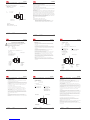
-
+
12
mA
Output:
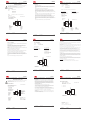
Input:
Resistance, 2-wire Resistance, 3-wire
RTD, 2-wire RTD, 3-wire RTD, 4-wire TC, internal CJC
TC, external CJC mV
Resistance, 4-wire
TC, dierence
or average,
with external CJC
mV, dierence
or average
RTD, dierence
or average
TC, dierence
or average,
with internal CJC
DK Indgangssignaler UK Input signals FR Signaux d’entrée DE Eingangssignale
DK Udgangssignal
UK Output signal
FR Signal de sortie
DE Ausgangssignal
M6
51
19
98
D = 1½" - 2"
Rørmontage - ovenfra Pipe-mounting – top view Montage tuyauterie -
vue de dessus
Rohrmontage - Draufsicht
DK UK FR
DE

7501QA01
LERBAKKEN 10, 8410 RØNDE DENMARK. WWW.PRELECTRONICS.COM
Revision date:
2015-09-16
Version Revision
V2R0
Page:
2/6
Ex ia installation
General installation instructions
The sensor circuit is not infallibly galvanic isolated from the supply output circuit. However, the
galvanic isolation between the circuits is capable of withstanding a test voltage of 500Vac during 1
minute.
The enclosure must be connected to the potential matching line
If the transmitter is physically connected to a possible source of heating or cooling, e.g. by
mounting to a process pipe or a temperature sensor, the temperature at the point of connection
shall be within the ambient temperature range as given in the certificate or this manual.
Cable entries and blanking elements shall be used that are suitable for the application and correctly
installed.
For installalation in zone 0 / EPL Ga, the transmitter must be installed such, that even in the event
of rare incidents, ignition sources due to impact and friction, sparks are excluded.
Protection degree of IP 54 according to EN 60529 is achieved if certified cable glands or conduit
entry devices are used that are suitable for the application and correctly installed.
Protection degree of IP 68 according to EN 60529 is only achieved if certified cable glands or
conduit entry devices are used that are suitable for the application and correctly installed with
sealing washers or Loctite sealant added to the threads of the sensor, blanking elements and cable
glands.
For group III (dust), electrostatic charging of the paint layer shall be avoided
7501QA01
LERBAKKEN 10, 8410 RØNDE DENMARK. WWW.PRELECTRONICS.COM
Revision date:
2015-09-16
Version Revision
V2R0
Page:
3/6
Ex nA, ic installation:
Certificate DEKRA15ATEX0058X
Marking II 3 G Ex nA IIC T6…T4 Gc
II 3 G Ex ic IIC T6...T4 Gc
II 3 D Ex ic IIIC T100°C Dc
Standards: EN 60079-0:2012, EN 60079-11:2012, EN60079-15:2010
Sensor
Terminal: 3,4,5,6
Ex ic
Uo: 9.6 VDC
Io: 28 mA
Po: 67 mW
Lo: 45 mH
Co: 28 μF
Supply
Terminal: 1,2
Ex ic
Ui: 35 VDC
Li: 0 μH
Ci: 2 nF
Supply
Terminal: 1,2
Ex nA
U : 35 VDC
1
2
6
5
4
3
+
-
Supply
7501
Hazardous area
Zone 2, 22
Non Hazardous Area
Type of protection Ex nA
O-ring Sealing : Silicone
T4: -40 ≤ Ta ≤ 85ºC T4 (7501A )
T4: -40 ≤ Ta ≤ 80ºC T4 (7501B )
T6: -40 ≤ Ta ≤ 60ºC T6
O-ring Sealing : FKM
T4: -20 ≤ Ta ≤ 85ºC (7501A )
T4: -20 ≤ Ta ≤ 80ºC (7501B )
T6: -20 ≤ Ta ≤ 60ºC
Type of protection Ex ic
T4: -40 ≤ Ta ≤ 85ºC T100ºC (7501A )
T4; -40 ≤ Ta ≤ 80ºC T100ºC (7501B )
T6: -40 ≤ Ta ≤ 60ºC T85 ºC
7501QA01
LERBAKKEN 10, 8410 RØNDE DENMARK. WWW.PRELECTRONICS.COM
Revision date:
2015-09-16
Version Revision
V2R0
Page:
1/6
7501 ATEX Installation
For safe installation of 7501 the following must be observed. The module shall only be installed by
qualified personnel who are familiar with the national and international laws, directives and
standards (EN60079-14) that apply to this area.
Year of manufacture can be taken from the first two digits in the serial number.
Ex ia installation:
ATEX Certificate DEKRA15ATEX0058X
Marking
Standards: EN 60079-0: 2012, EN 60079-11: 2012, EN60079-26:2007
Non Hazardous Area
Hazardous area
Zone 0, 1, 2, 20, 21, 22, (Mines)
II 1 G Ex ia IIC T6...T4 Ga
II 1 D Ex ia IIIC T100°C Da
I M1 Ex ia I Ma ( 7501B )
Sensor
Terminal: 3,4,5,6
Uo: 9.6 VDC
Io: 28 mA
Po: 67 mW
Lo: 35 mH
Co: 3.5 μF
Supply
Terminal: 1,2
Ui: 30 VDC
Ii: 120 mA
Pi: 0.84 W
Li: 0 μH
Ci: 2 nF
T4: -40 ≤ Ta ≤ 85ºC T100 ºC ( 7501A)
T4: -40 ≤ Ta ≤ 80ºC T100 ºC ( 7501B)
T5: -40 ≤ Ta ≤ 60ºC T75 ºC
T6: -40 ≤ Ta ≤ 45ºC T60 ºC
1
2
6
5
4
3
+
-
Barrier
7501
7501QA01
LERBAKKEN 10, 8410 RØNDE DENMARK. WWW.PRELECTRONICS.COM
Revision date:
2015-09-16
Version Revision
V2R0
Page:
5/6
Ex d, tb installation:
ATEX Certificate DEKRA15ATEX0058X
Marking
Standards: EN 60079-0:2012, EN 60079-1:2007, EN60079-31:2014
Non Hazardous Area
Hazardous area
Zone 1, 2, 21, 22
II 2 G Ex d IIC T6…T4 Gb
II 2 D Ex tb IIIC T100°C Db
Terminal: 3,4,5,6
Sensor: RTD or TC
Terminal: 1,2
Umax: 35 VDC
1
2
6
5
4
3
+
-
Supply
7501
Type of protection Ex d
T4,T5: -40 ≤ Ta ≤ 85ºC (7501A )
T4,T5: -40 ≤ Ta ≤ 80ºC (7501B )
T6: -40 ≤ Ta ≤ 70ºC
Type of protection Ex tb
O-ring Sealing : Silicone
-40 ≤ Ta ≤ 85ºC T100°C (7501A )
-40 ≤ Ta ≤ 80ºC T100°C (7501B )
-40 ≤ Ta ≤ 70ºC T85°C
O-ring Sealing : FKM
-20 ≤ Ta ≤ 85ºC T100°C (7501A )
-20 ≤ Ta ≤ 80ºC T100°C (7501B )
-20 ≤ Ta ≤ 70ºC T85°C
7501QA01
LERBAKKEN 10, 8410 RØNDE DENMARK. WWW.PRELECTRONICS.COM
Revision date:
2015-09-16
Version Revision
V2R0
Page:
4/6
Ex nA, ic installation:
For an ambient temperature exceeding 70 °C, heat resistant cables and cable glands suitable for at
least 90°C shall be used.
If the transmitter is physically connected to a possible source of heating or cooling, e.g. by
mounting to a process pipe or a temperature sensor, the temperature at the point of connection
shall be within the ambient temperature range as given in the certificate.
Cable entries and blanking elements shall be used that are suitable for the application and correctly
installed.
The enclosure must be connected to the potential matching line
Applied screw terminal torque is max 0.4 Nm on all terminals.
Protection degree of IP 54 according to EN 60529 is achieved if certified cable glands or conduit
entry devices are used that are suitable for the application and correctly installed.
Protection degree of IP 68 according to EN 60529 is only achieved if certified cable glands or
conduit entry devices are used that are suitable for the application and correctly installed with
sealing washers or Loctite sealant added to the threads of the sensor, blanking elements and cable
glands.
For group III (dust), electrostatic charging of the paint layer shall be avoided
7501QA01
LERBAKKEN 10, 8410 RØNDE DENMARK. WWW.PRELECTRONICS.COM
Revision date:
2015-09-16
Version Revision
V2R0
Page:
6/6
Ex d, tb installation:
Unused cable entries must be sealed by the blanking elements supplied with the 7501 or other Ex d
and/or Ex tb certified blanking elements suitable for the application. .
Only Ex d and/or Ex tb certified cable and cable glands shall be used that are suitable for the
application and correctly installed.
Protection degree of IP 54 according to EN 60529 is achieved if Ex d certified cable glands or
conduit entry devices are used that are suitable for the application and correctly installed.
Protection degree of IP 68 according to EN 60529 is only achieved if Ex d certified cable glands or
conduit entry devices are used that are suitable for the application and correctly installed with sealing
washers or Loctite sealant added to the threads of the sensor, blanking elements and cable glands.
The display cover must be screwed all the way in and the safety catch must be fastened before
putting into service. Do not open display cover until 30 minutes after disconnecting power to the
equipment allowing internal capacitors to discharge, or do not open display cover unless area is
known to be safe
For an ambient temperature exceeding 70 °C, heat resistant cables and cable glands suitable for at
least 90°C shall be used.
If the transmitter is physically connected to a possible source of heating or cooling, e.g. by mounting
to a process pipe or a temperature sensor, the temperature at the point of connection shall be within
the ambient temperature range as given in the certificate. The sensor shall be suitable for use as
entry device on an Ex d enclosure and shall not add volume to the 7501 enclosure. The thread of the
sensor must be in compliance with EN60079-1 / EN60079-31.
The enclosure must be connected to the potential matching line.
When the process temperature range exceeds the service temperature range it shall be verified by
on-site temperature measurements, taking the worst case conditions into account, that the service
temperature does not exceed the range of the module.
For group III (dust), electrostatic charging of the paint layer shall be avoided
No modification to the enclosure is allowed by the customer except as mentioned in the manual or
installation drawing.
7501QC01
LERBAKKEN 10, 8410 RØNDE DENMARK. WWW.PRELECTRONICS.COM
Revision date:
2015-09-22
Version Revision
V2R0
Page:
2/3
Explosion proof:
Explosion proof for Hazardous area
Class I, Division 1, Groups ABCD;
Class II, Division 1, Groups EFG;
Class III
Ex d IIC, Class I, Zone 1
T4,T5: -20/-40 ≤ Ta ≤ 85ºC T100°C
T6: -20/-40 ≤ Ta ≤ 70ºC T85°C
Non Hazardous Area
1
2
6
5
4
3
+
-
Supply
7501
Terminal: 1,2
Umax: 35 VDC
Terminal: 3,4,5,6
Sensor: RTD or TC
O-ring Sealing
Silicone rubber:-40°C ≤Ta ≤ +85°C
FKM rubber: -20°C ≤Ta ≤ +85°C
7501QC01
LERBAKKEN 10, 8410 RØNDE DENMARK. WWW.PRELECTRONICS.COM
Revision date:
2015-09-22
Version Revision
V2R0
Page:
1/3
7501 CSA Installation
For safe installation of 7501 the following must be observed. The module shall only be installed by
qualified personnel who are familiar with the national and international laws, directives and
standards that apply to this area.
Intrinsic Safe Installation:
Hazardous classified Location
Class I,Division1, Groups, ABCD;
Class II,Group EFG;
Class III, Division 1.
Class I, Zone 0, IIC
Ex/AEx ia IIC Ga
Warning:
Substitution of components may impair intrinsic safety.
The module must be installed according to the installation codes stipulated in the Canadian
Electrical Code (CEC) or for US the National Electrical Code (NEC).
Non classified Location
Terminal: 3,4,5,6
Uo: 9.6 VDC
Io: 28 mA
Po: 67 mW
Lo: 35 mH
Co: 3.5 μF
Terminal: 1,2
Ui: 30 VDC
Ii: 120 mA
Pi: 0.84 W
Li: 0 μH
Ci: 2 nF
UM < 250V
Voc or Uo < Vmax or Ui
Isc or Io < Imax or Ii
Po < Pi
Ca or Co > Ci + Ccable
La or Lo > Li + Lcable
The barrier must not
be connected to any
associated apparatus
which uses or
generates more than
250 VRMS
1
2
6
5
4
3
+
-
Barrier
7501
T4: -40 ≤ Ta ≤ 85ºC T100 ºC
T5: -40 ≤ Ta ≤ 60ºC T75 ºC
T6: -40 ≤ Ta ≤ 45ºC T60 ºC
7501QC01
LERBAKKEN 10, 8410 RØNDE DENMARK. WWW.PRELECTRONICS.COM
Revision date:
2015-09-22
Version Revision
V2R0
Page:
3/3
Explosion proof Installation.
Conduit and sensor connections must be in NPT modified threads.
Only third party certified sensors suitable for “Class I, Division 1 / Zone 1, Groups ABCD / IIC“ may
be connected to the Temperature Transmitter.
For Class I Group A installation and Class I Zone 1 installation, conduit seal is required within 18
inches of enclosure.
For an ambient temperature exceeding 70°C, heat resistant cables and cables suitable for at least
90°C shall be used.
The display cover must be screwed all the way in and the safety catch must be fastened before
putting the module into service.
Do not open / remove front cover unless area is known to be safe.
The remote temperature sensor must comply with the requirements for installation in hazardous
locations “Class I, Division 1 / Zone 1, Groups ABCD / IIC”
The remote temperature sensor must comply with the requirements for Ex d installation
Only certified cable and cable glands shall be used that are suitable for the application and
correctly installed.
For protection according to Type 4X / IP66 use Loctite 577 on threads of sensor and cable glands.
The enclosure must be connected to the potential matching line
Unused cable entries must be sealed by the blanking elements supplied with the 7501 or other Ex
certified blanking elements.
If the transmitter is physically connected to a possible source of heating or cooling, e.g. by
mounting to a process pipe or a temperature sensor, the temperature at the point of connection
shall be within the ambient temperature range as given in the certificate.
When the process temperature range exceeds the service temperature range it shall be verified by
on-site temperature measurements, taking the worst case conditions into account, that the service
temperature does not exceed the range of the module.
For Class II, III, electrostatic charging of the paint layer shall be avoided.
No modification to the enclosure is allowed by the customer except as mentioned in the manual or
installation drawing.

7501QI01
LERBAKKEN 10, 8410 RØNDE DENMARK. WWW.PRELECTRONICS.COM
Revision date:
2015-09-16
Version Revision
V2R0
Page:
2/6
Ex ia installation
General installation instructions
The sensor circuit is not infallibly galvanic isolated from the supply output circuit. However, the
galvanic isolation between the circuits is capable of withstanding a test voltage of 500Vac during 1
minute.
The enclosure must be connected to the potential matching line.
If the transmitter is physically connected to a possible source of heating or cooling, e.g. by
mounting to a process pipe or a temperature sensor, the temperature at the point of connection
shall be within the ambient temperature range as given in the certificate or in this manual.
Cable entries and blanking elements shall be used that are suitable for the application and correctly
installed.
For installalation in zone 0 / EPL Ga, the transmitter must be installed such, that even in the event
of rare incidents, ignition sources due to impact and friction, sparks are excluded.
Protection degree of IP 54 according to IEC 60529 is achieved if certified cable glands or conduit
entry devices are used that are suitable for the application and correctly installed.
Protection degree of IP 68 according to IEC 60529 is only achieved if certified cable glands or
conduit entry devices are used that are suitable for the application and correctly installed with
sealing washers or Loctite sealant added to the threads of the sensor, blanking elements and cable
glands.
For group III (dust), electrostatic charging of the paint layer shall be avoided.
7501QI01
LERBAKKEN 10, 8410 RØNDE DENMARK. WWW.PRELECTRONICS.COM
Revision date:
2015-09-16
Version Revision
V2R0
Page:
3/6
Ex nA, ic installation:
Certificate IECEx DEK 15.0039 X
Marking Ex nA IIC T6…T4 Gc
Ex ic IIC T6…T4 Gc
Ex ic IIIC T100°C Dc
Standards: IEC 60079-0: 2011, IEC 60079-11: 2011, IEC 60079-15: 2010
Sensor
Terminal: 3,4,5,6
Ex ic
Uo: 9.6 VDC
Io: 28 mA
Po: 67 mW
Lo: 45 mH
Co: 28 μF
Supply
Terminal: 1,2
Ex ic
Ui: 35 VDC
Li: 0 μH
Ci: 2 nF
Supply
Terminal: 1,2
Ex nA
Umax : 35 VDC
1
2
6
5
4
3
+
-
Supply
7501
Hazardous area
Zone 2, 22 Non Hazardous Area
Type of protection Ex nA
O-ring Sealing : Silicone
T4: -40 ≤ Ta ≤ 85ºC T4 (7501A )
T4: -40 ≤ Ta ≤ 80ºC T4 (7501B )
T6: -40 ≤ Ta ≤ 60ºC T6
O-ring Sealing : FKM
T4: -20 ≤ Ta ≤ 85ºC (7501A )
T4: -20 ≤ Ta ≤ 80ºC (7501B )
T6: -20 ≤ Ta ≤ 60ºC
Type of protection Ex ic
T4: -40 ≤ Ta ≤ 85ºC T100ºC (7501A )
T4; -40 ≤ Ta ≤ 80ºC T100ºC (7501B )
T6: -40 ≤ Ta ≤ 60ºC T85 ºC
7501QI01
LERBAKKEN 10, 8410 RØNDE DENMARK. WWW.PRELECTRONICS.COM
Revision date:
2015-09-16
Version Revision
V2R0
Page:
1/6
7501 IECEx Installation
For safe installation of 7501 the following must be observed. The module shall only be installed by
qualified personnel who are familiar with the national and international laws, directives and
standards (IEC60079-14) that apply to this area.
Year of manufacture can be taken from the first two digits in the serial number.
Ex ia installation:
Certificate IECEx DEK 15.0039 X
Marking
Standards: IEC 60079-0: 2011, IEC 60079-11: 2011, IEC 60079-26: 2007
Hazardous area
Zone 0, 1, 2, 20, 21, 22, Mines
Non Hazardous Area
T4: -40 ≤ Ta ≤ 85ºC T100 ºC ( 7501A)
T4: -40 ≤ Ta ≤ 80ºC T100 ºC ( 7501B)
T5: -40 ≤ Ta ≤ 60ºC T75 ºC
T6: -40 ≤ Ta ≤ 45ºC T60 ºC
Ex ia IIC T6...T4 Ga
Ex ia IIIC T100°C Da
Ex ia I Ma (7501B )
Sensor
Terminal: 3,4,5,6
Uo: 9.6 VDC
Io: 28 mA
Po: 67 mW
Lo: 35 mH
Co: 3.5 μF
Supply
Terminal: 1,2
Ui: 30 VDC
Ii: 120 mA
Pi: 0.84 W
Li: 0 μH
Ci: 2 nF
1
2
6
5
4
3
+
-
Barrier
7501
7501QI01
LERBAKKEN 10, 8410 RØNDE DENMARK. WWW.PRELECTRONICS.COM
Revision date:
2015-09-16
Version Revision
V2R0
Page:
5/6
Ex d, tb installation:
Certificate IEC DEK 15.0039 X
Marking
Standards:IEC 60079-0: 2011, IEC 60079-1: 2007, IEC 60079-31: 2013
Non Hazardous Area
Hazardous area
Zone 1, 2, 21, 22
Ex d IIC T6…T4 Gb
Ex tb IIIC T100°C Db
Terminal: 3,4,5,6
Sensor: RTD or TC
Terminal: 1,2
Umax: 35 VDC
Type of protection Ex tb
O-ring Sealing : Silicone
-40 ≤ Ta ≤ 85ºC T100°C (7501A )
-40 ≤ Ta ≤ 80ºC T100°C (7501B )
-40 ≤ Ta ≤ 70ºC T85°C
O-ring Sealing : FKM
-20 ≤ Ta ≤ 85ºC T100°C (7501A )
-20 ≤ Ta ≤ 80ºC T100°C (7501B )
-20 ≤ Ta ≤ 70ºC T85°C
1
2
6
5
4
3
+
-
Supply
7501
Type of protection Ex d
T4,T5: -40 ≤ Ta ≤ 85ºC (7501A )
T4,T5: -40 ≤ Ta ≤ 80ºC (7501B )
T6: -40 ≤ Ta ≤ 70ºC
7501QI01
LERBAKKEN 10, 8410 RØNDE DENMARK. WWW.PRELECTRONICS.COM
Revision date:
2015-09-16
Version Revision
V2R0
Page:
4/6
Ex nA, ic installation:
For an ambient temperature exceeding 70°C, heat resistant cables and cable glands suitable for at
least 90°C shall be used.
If the transmitter is physically connected to a possible source of heating or cooling, e.g. by
mounting to a process pipe or a temperature sensor, the temperature at the point of connection
shall be within the ambient temperature range as given in the certificate.
Cable entries and blanking elements shall be used that are suitable for the application and correctly
installed.
The enclosure must be connected to the potential matching line
Applied screw terminal torque is max 0.4 Nm on all terminals.
Protection degree of IP 54 according to EN 60529 is achieved if certified cable glands or conduit
entry devices are used that are suitable for the application and correctly installed.
Protection degree of IP 68 according to EN 60529 is only achieved if certified cable glands or
conduit entry devices are used that are suitable for the application and correctly installed with
sealing washers or Loctite sealant added to the threads of the sensor, blanking elements and cable
glands.
For group III (dust), electrostatic charging of the paint layer shall be avoided
7501QI01
LERBAKKEN 10, 8410 RØNDE DENMARK. WWW.PRELECTRONICS.COM
Revision date:
2015-09-16
Version Revision
V2R0
Page:
6/6
Ex d, tb installation
Unused cable entries must be sealed by the blanking elements supplied with the 7501 or other Ex d and/or
Ex tb certified blanking elements suitable for the application.
Only Ex d and/or Ex tb certified cable and cable glands shall be used that are suitable for the application and
correctly installed.
Protection degree of IP 54 according to IEC 60529 is achieved if Ex d certified cable glands or conduit entry
devices are used that are suitable for the application and correctly installed.
Protection degree of IP 68 according to IEC 60529 is only achieved if Ex d certified cable glands or conduit
entry devices are used that are suitable for the application and correctly installed with sealing washers or
Loctite sealant added to the threads of the sensor, blanking elements and cable glands.
The display cover must be screwed all the way in and the safety catch must be fastened before putting into
service. Do not open display cover until 30 minutes after disconnecting power to the equipment allowing
internal capacitors to discharge, or do not open display cover unless area is known to be safe
For an ambient temperature exceeding 70 °C, heat resistant cables and cable glands suitable for at least
90°C shall be used.
If the transmitter is physically connected to a possible source of heating or cooling, e.g. by mounting to a
process pipe or a temperature sensor, the temperature at the point of connection shall be within the ambient
temperature range as given in the certificate. The sensor shall be suitable for use as entry device on an Ex d
enclosure and shall not add volume to the 7501 enclosure. The thread of the sensor must be in compliance
with EN60079-1 / EN60079-31.
The enclosure must be connected to the potential matching line.
When the process temperature range exceeds the service temperature range it shall be verified by on-site
temperature measurements, taking the worst case conditions into account, that the service temperature does
not exceed the range of the module.
For group III (dust), electrostatic charging of the paint layer shall be avoided
No modification to the enclosure is allowed by the customer except as mentioned in the manual or
installation drawing.
7501QF01
LERBAKKEN 10, 8410 RØNDE DENMARK. WWW.PRELECTRONICS.COM
Revision date:
2015-07-28
Version Revision
V1R0
Page:
2/5
The entity concept
The Transmitter must be installed according to National Electrical Code (ANSI-NFPA 70) and shall be
installed with the enclosure, mounting, and spacing segregation requirement of the ultimate application.
Equipment that is FM-approved for intrinsic safety may be connected to barriers based on the ENTITY
CONCEPT. This concept permits interconnection of approved transmitters, meters and other devices in
combinations which have not been specifically examined by FM, provided that the agency's criteria are
met. The combination is then intrinsically safe, if the entity concept is acceptable to the authority having
jurisdiction over the installation.
The entity concept criteria are as follows:
The intrinsically safe devices, other than barriers, must not be a source of power.
The maximum voltage Ui(VMAX) and current Ii(IMAX), and maximum power Pi(Pmax), which the device can
receive and remain intrinsically safe, must be equal to or greater than the voltage (Uo or VOC or Vt) and
current (Io or ISC or It) and the power Po which can be delivered by the barrier.
The sum of the maximum unprotected capacitance (Ci) for each intrinsically device and the interconnect-
ing wiring must be less than the capacitance (Ca) which can be safely connected to the barrier.
The sum of the maximum unprotected inductance (Li) for each intrinsically device and the interconnecting
wiring must be less than the inductance (La) which can be safely connected to the barrier.
The entity parameters Uo,VOC or Vt and Io,ISC or It, and Ca and La for barriers are provided by the barrier
manufacturer.
For Class II and Class III installations where rigid conduit is not used, seal cable entries against dust and
fibres using a NRTL listed cable gland fitting.
7501QF01
LERBAKKEN 10, 8410 RØNDE DENMARK. WWW.PRELECTRONICS.COM
Revision date:
2015-07-28
Version Revision
V1R0
Page:
1/5
FM Installation drawing 7501
For safe installation of 7501 the following must be observed. The module shall only be installed by
qualified personnel who are familiar with the national and international laws, directives and
standards that apply to this area.
Intrinsic safe installation:
Hazardous classified Location
Class I,II,II Division1 Groups, ABCDEFG
Class I, Zone 0, IIC, Zone 20
T4: -40 ≤ Ta ≤ 85ºC
T5: -40 ≤ Ta ≤ 60ºC
T6: -40 ≤ Ta ≤ 40ºC
Zone 20 Temperature Class:
-40 ≤ Ta ≤ 85ºC T100 ºC
-40 ≤ Ta ≤ 60ºC T75 ºC
-40 ≤ Ta ≤ 40ºC T60 ºC
Non classified Location
Terminal: 3,4,5,6
Uo: 9.6 VDC
Io: 28 mA
Po: 67 mW
Lo: 35 mH
Co: 3.5 μF
Terminal: 1,2
Ui: 30 VDC
Ii: 120 mA
Pi: 0.84 W
Li: 0 μH
Ci: 2 nF
UM < 250V
Voc or Uo < Vmax or Ui
Isc or Io < Imax or Ii
Po < Pi
Ca or Co > Ci + Ccable
La or Lo > Li + Lcable
The barrier must not
be connected to any
associated apparatus
which uses or
generates more than
250 VRMS
1
2
6
5
4
3
+
-
Barrier
7501
7501QF01
LERBAKKEN 10, 8410 RØNDE DENMARK. WWW.PRELECTRONICS.COM
Revision date:
2015-07-28
Version Revision
V1R0
Page:
3/5
Non Incendive installation:
Hazardous classified Location
Class I,II,III ,Division 2, Groups, ABCDFG
Class I, Zone 2, IIC
Non classified Location
Terminal: 1,2
Vmax: 35 VDC
1
2
6
5
4
3
+
-
7501
Vmax
35V
T4: -40 ≤ Ta ≤ 85ºC
T6: -40 ≤ Ta ≤ 60ºC
Terminal: 3,4,5,6
Sensor: RTD or TC
O-ring Sealings
Silicone rubber:-40°C ≤Ta ≤ +85°C
FKM rubber: -20°C ≤Ta ≤ +85°C
Protection: Indoor and Outdoor TYPE 4X or IP66

7501QF01
LERBAKKEN 10, 8410 RØNDE DENMARK. WWW.PRELECTRONICS.COM
Revision date:
2015-07-28
Version Revision
V1R0
Page:
5/5
Explosion proof / Dust ignition proof installation.
The enclosure must be installed such, that even in the event of rare incidents, ignition sources due to impact
and friction, sparks are excluded.
Unused cable entries must be sealed by approved sealing plugs.
Certified cable and cable glands shall be used that are suitable for the application and correctly installed or
the cables must be run in conduit.
For an ambient temperature exceeding 70 °C, heat resistant cables and cable glands suitable for at least
90°C shall be used.
For process temperatures above 85°C or below -20/-40°C installer must verify by measurements that the
service temperature of the 7501 module is held within this range taking worst conditions into account.
The display cover must be screwed all the way in and the safety catch must be fastened before operation.
Protection degree of IP 66 or TYPE4X is only achieved if certified cable glands or conduit entry devices are
used that are suitable for the application and correctly installed with sealing washers or Loctite sealant is
added to the threads of the sensor, blanking elements and cable glands.
The enclosure must be connected to the potential matching line.
Warning.
Do not open display cover unless area is known to be safe.
For installation in Canada the following must be taken into account:
All openings for conduit and sensor connection must be in NPT threads.
For Class I Group A installation, conduit seal is required within 18 inches of the enclosure.
For Class I Zone I installation, conduit seal is required within 18 inches of the enclosure.
7501QF01
LERBAKKEN 10, 8410 RØNDE DENMARK. WWW.PRELECTRONICS.COM
Revision date:
2015-07-28
Version Revision
V1R0
Page:
4/5
Explosion proof / Dust ignition proof installation:
1
2
6
5
4
3
+
-
Supply
7501
Hazardous area
Class I, II, III Division 1, Groups ABCDEFG
Class I Zone 1, Ex/AEx d IIC T6
Non Hazardous Area
Terminal: 1,2
Umax: 35 VDC
Terminal: 3,4,5,6
Sensor: RTD or TC
T6: -20/-40 ≤ Ta ≤ 70ºC
T5, T4: -20/-40 ≤ Ta ≤ 85ºC
O-ring Sealings
Silicone rubber:-40°C ≤Ta ≤ +85°C
FKM rubber: -20°C ≤Ta ≤ +85°C
Protection: Indoor and Outdoor Type 4X or IP66
7501QB01
LERBAKKEN 10, 8410 RØNDE DENMARK. WWW.PRELECTRONICS.COM
Revision date:
2015-09-16
Version Revision
V2R0
Page:
2/6
Instalação do Ex ia
Instruções de instalação gerais
O circuito do sensor não é infalivelmente galvânico-isolado do circuito de saída de alimentação.
Contudo, a isolação galvânica entre os circuitos é capaz de resistir a teste de tensão de 500Vac
durante 1 minuto.
O equipamento deve ser conectado à linha potencial correspondente
Se o transmissor estiver fisicamente conectado a uma possível fonte de calor ou resfriamento, por
exemplo, através da montagem de um tubo de processo ou sensor de temperatura, a temperatura
no ponto de conexão deve estar entre a faixa de temperatura ambiente determinada no certificado
ou neste manual.
As entradas dos cabos e elementos de supressão devem ser usadas adequadamente para
aplicação INMETRO, aprovada e instalada corretamente.
Para instalação em zona 0 / EPL Ga, se aplicam as seguintes instruções:
O transmissor deve ser instalado de modo que, mesmo em um evento raro de incidente, fontes de
ignição devido a impactos e fricção, faíscas sejam evitadas.
O grau de proteção do IP 54 de acordo com a IEC 60529 é alcançado se o certificado prensa-
cabos ou dispositivos de entrada de conduíte são usados e adequados para a aplicação e
instalados corretamente.
O grau de proteção do IP 68 de acordo com a IEC 60529 é apenas alcançado se o certificado
prensa-cabos ou dispositivos de entrada de conduíte são usados e adequados para aplicação e
instalados corretamente com selos de vedação ou selante Loctite adicionados para as linhas do
sensor, elementos de supressão e prensa-cabos.
Cuidado
Cuidados especiais devem ser tomados para evitar o acúmulo de carga eletrostática no
equipamento devido ao repetitivo processo de carregamento, por exemplo, fluído de líquidos em
alta velocidade, pós ou partículas de plásticos transportados pelo ar e outras cargas eletrostáticas
para a superfície.
7501QB01
LERBAKKEN 10, 8410 RØNDE DENMARK. WWW.PRELECTRONICS.COM
Revision date:
2015-09-16
Version Revision
V2R0
Page:
1/6
7501 Desenho de Instalação INMETRO
Para instalação segura do 7501 o seguinte deve ser observado. O módulo deve ser instalado,
apenas por pessoas qualificadas as quais estão familiarizadas com as normas nacionais e
internacionais, diretrizes e padrões (IEC60079-14) que se aplicam a esta área.
Instalação Segura do Ex ia installation:
Certificado DEKRA 15.0014X
Marca
Normas : ABNT NBR IEC 60079-0: 2013, ABNT NBR IEC 60079-11: 2013
Áreas não perigosas
Áreas Perigosas
Zona 0, 1, 2, 20, 21, 22
T4: -40 ≤ Ta ≤ 85ºC T100 ºC (7501A)
T4: -40 ≤ Ta ≤ 80ºC T100 ºC (7501B)
T5: -40 ≤ Ta ≤ 60ºC T100 ºC
T6: -40 ≤ Ta ≤ 45ºC T100 ºC
Ex ia IIC T6...T4 Ga
Ex ia IIIC T100°C Da
Terminal do
sensor: 3,4,5,6
Uo: 9.6 VDC
Io: 28 mA
Po: 67 mW
Lo: 35 mH
Co: 3.5 μF
Terminal de
alimentação: 1,2
Ui: 30 VDC
Ii: 120 mA
Pi: 0.84 W
Li: 0 μH
Ci: 2 nF
1
2
6
5
4
3
+
-
Barrier
7501
7501QB01
LERBAKKEN 10, 8410 RØNDE DENMARK. WWW.PRELECTRONICS.COM
Revision date:
2015-09-16
Version Revision
V2R0
Page:
3/6
Instalação ic, Ex nA:
Certificado DEKRA 15.0014X
Marca Ex nA IIC T6…T4 Gc
Ex ic IIC T6…T4 Gc
Ex ic IIIC T100°C Dc
Normas: ABNT NBR IEC 60079-0: 2013, ABNT NBR IEC 60079-15: 2012
Terminal do
sensor: 3,4,5,6
Ex ic
Uo: 9.6 VDC
Io: 28 mA
Po: 67 mW
Lo: 45 mH
Co: 28 μF
Terminal de
alimentação: 1,2
Ex ic
Ui: 35 VDC
Li: 0 μH
Ci: 2 nF
Terminal de
alimentação: 1,2
Ex nA
U : 35 VDC
1
2
6
5
4
3
+
-
Supply
7501
Áreas perigosas
Zona 2, 22
Áreas não perigosas
Ex nA
Anel de vedação O : Silicone
T4: -40 ≤ Ta ≤ 85ºC T4 (7501A )
T4: -40 ≤ Ta ≤ 80ºC T4 (7501B )
T6: -40 ≤ Ta ≤ 60ºC T6
Anel de vedação O : FKM
T4: -20 ≤ Ta ≤ 85ºC (7501A )
T4: -20 ≤ Ta ≤ 80ºC (7501B )
T6: -20 ≤ Ta ≤ 60ºC
Ex ic
T4: -40 ≤ Ta ≤ 85ºC T100ºC (7501A )
T4; -40 ≤ Ta ≤ 80ºC T100ºC (7501B )
T6: -40 ≤ Ta ≤ 60ºC T85 ºC
7501QB01
LERBAKKEN 10, 8410 RØNDE DENMARK. WWW.PRELECTRONICS.COM
Revision date:
2015-09-16
Version Revision
V2R0
Page:
5/6
Instalação tb, Ex d:
Certificado DEKRA 15.0014X
Marca
Normas ABNT NBR IEC 60079-0: 2013, ABNT NBR IEC 60079-1: 2009,
ABNT NBR IEC 60079-31:2014
Áreas não perigosas
Áreas perigosas
Zona 1, 2, 21, 22
Ex d IIC T6…T4 Gb
Ex tb IIIC T100°C Db
Terminal: 3,4,5,6
Sensor: RTD ou TC
Terminal: 1,2
Alimentação: 35 VDC
1
2
6
5
4
3
+
-
Supply
7501
Ex d
T4,T5: -40 ≤ Ta ≤ 85ºC (7501A )
T4,T5: -40 ≤ Ta ≤ 80ºC (7501B )
T6: -40 ≤ Ta ≤ 70ºC
Ex tb
Anel de vedação O: Silicone
-40 ≤ Ta ≤ 85ºC T100°C (7501A )
-40 ≤ Ta ≤ 80ºC T100°C (7501B )
-40 ≤ Ta ≤ 70ºC T85°C
Anel de vedação O: FKM
-20 ≤ Ta ≤ 85ºC T100°C (7501A )
-20 ≤ Ta ≤ 80ºC T100°C (7501B )
-20 ≤ Ta ≤ 70ºC T85°C
7501QB01
LERBAKKEN 10, 8410 RØNDE DENMARK. WWW.PRELECTRONICS.COM
Revision date:
2015-09-16
Version Revision
V2R0
Page:
4/6
Instalação icx, Ex nA:
Para uma temperatura ambiente excedendo 70 ºC, cabos resistentes ao calor e prensa-cabos
adequados para pelo menos 90 ºC devem ser usados.
Se o transmissor estiver fisicamente conectado a uma possível fonte de calor ou resfriamento, por
exemplo, através da montagem de um tubo de processo ou sensor de temperatura, a temperatura
no ponto de conexão deve estar entre a faixa de temperatura ambiente determinada no certificado
ou neste manual.
As entradas dos cabos e elementos de supressão devem ser usadas adequadamente para a
aplicação e instaladas corretamente.
O equipamento deve ser conectado à linha potencial correspondente
O torque aplicado no terminal de parafusos é no máximo 0.4 Nm em todos os terminais.
O grau de proteção do IP 54 de acordo com a IEC 60529 é alcançado se o certificado prensa-
cabos ou dispositivos de entrada de conduíte são usados e adequados para a aplicação e
instalados corretamente.
O grau de proteção do IP 68 de acordo com a IEC 60529 é apenas alcançado se o certificado
prensa-cabos ou dispositivos de entrada de conduíte são usados e adequados para aplicação e
instalados corretamente com selos de vedação ou selante Loctite adicionados para as linhas do
sensor, elementos de supressão e prensa-cabos.
Cuidado
Cuidados especiais devem ser tomados para evitar o acúmulo de carga eletrostática no
equipamento devido ao repetitivo processo de carregamento, por exemplo, fluído de líquidos em
alta velocidade, pós ou partículas de plásticos transportados pelo ar e outras cargas eletrostáticas
para a superfície
7501QB01
LERBAKKEN 10, 8410 RØNDE DENMARK. WWW.PRELECTRONICS.COM
Revision date:
2015-09-16
Version Revision
V2R0
Page:
6/6
Instalação tb, Ex d:
Entradas de cabos não utilizadas devem ser seladas pelo INMETRO, de acordo com a aprovação de
elementos de supressão adequados para a aplicação e instalados corretamente.
Apenas o certificado de cabos e prensa-cabos do INMETRO para Ex d / tb deve ser usado, que são
adequados para a aplicação e instalados corretamente.
O Sensor / Sonda aplicado deve ser adequado para a aplicação, instalado corretamente, e deve ser
certificado pelo INMETRO.
Se o transmissor estiver fisicamente conectado a uma possível fonte de calor ou resfriamento, por exemplo,
através da montagem de um tubo de processo ou sensor de temperatura, a temperatura no ponto de
conexão deve estar entre a faixa de temperatura ambiente dada no certificado. O sensor deve ser adequado
para ser usado como entrada de equipamento no equipamento Ex d e nenhum volume deve ser adicionado
no enclosure do 7501.
O grau de proteção do IP 54 de acordo com a IEC 60529 é alcançado se o certificado Ex de prensa-cabos
ou dispositivos de entrada de conduíte são usados e adequados para a aplicação e instalados
corretamente.
O grau de proteção do IP 68 de acordo com a IEC 60529 é apenas alcançado se o certificado Ex de prensa-
cabos ou dispositivos de entrada de conduíte são usados e adequados para aplicação e instalados
corretamente com selos de vedação ou selante Loctite adicionados para as linhas do sensor, elementos de
supressão e prensa-cabos.
A tampa do display deve ser parafusada em todos os pontos e o fecho de segurança deve ser ajustado
antes de colocá-lo em serviço. Não abra a tampa do display até 30 minutos depois de desconectar a
alimentação a fim de permitir que os capacitores internos descarreguem, ou não abra a tampa do display a
menos que a área seja conhecida como segura.
Para uma temperatura ambiente que excede 70 ºC, cabos resistentes a aquecimento e prensa-cabos
adequados para pelo menos 90 ºC devem ser usados.
O equipamento deve ser conectado em uma linha potencial correspondente.
Quando a faixa de temperatura do processo excede a faixa de temperatura de serviço ela deve ser
verificada através de medições de temperatura no local, levando a pior condição em conta, que a
temperatura de serviço não exceda a faixa do módulo.
Cuidado
Cuidados especiais devem ser tomados para evitar o acúmulo de carga eletrostática no equipamento devido
ao repetitivo processo de carregamento, por exemplo, fluído de líquidos em alta velocidade, pós ou
partículas de plásticos transportados pelo ar e outras cargas eletrostáticas para a superfície.
Nenhuma modificação no equipamento pelo cliente é permitida exceto o que é mencionado no manual ou no
desenho de instalação.
-
 1
1
-
 2
2
-
 3
3
-
 4
4


PR electronics 7501 Series Guide d'installation
- Taper
- Guide d'installation
dans d''autres langues
Autres documents
-
PR 5102 Manuel utilisateur
-
CHAUVIN ARNOUX C.A3420 Manuel utilisateur
-
red lion IAMS 0001 Manuel utilisateur
-
-
-
-
Baumer 2222 Fiche technique
-
-
-
WIKA TIF50-S Manuel utilisateur