Klein Tools ET600 Manuel utilisateur
- Catégorie
- Testeurs de réseau câblé
- Taper
- Manuel utilisateur

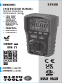
INSTRUCTION MANUAL
ENGLISH
FRANÇAIS p. 25
ESPAÑOL pg. 13
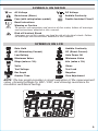
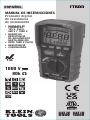
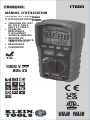
Digital Insulation
Resistance Tester
• 125V, 250V,
500V, AND
1000V TEST
VOLTAGES
• INSULATION
RESISTANCE
RANGE UP TO
4000 MΩ
• MEASURES
1000V AC/DC
• RESISTANCE
• CONTINUITY
ET600
1000V
1m
5000573
Digital Insulation
Resistance Tester
80k
Ω
CAT IV
600V
CAT III
1000V

2
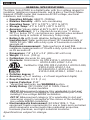
GENERAL SPECIFICATIONS
The Klein Tools ET600 is a digital tester with four voltage ranges for
insulation resistance measurements, and is also a True Root-Mean-
Squared (TRMS) tester that measures AC/DC voltage, electrical
resistance, and continuity.
• Operating Altitude: 6562 ft. (2000m)
• Relative Humidity: <80% non-condensing
• Operating Temp: 14°F to 122°F (-10°C to 50°C)
• Storage Temp: -4°F to 140°F (-30°C to 60°C)
• Accuracy: Values stated at 65°F to 83°F (18°C to 28°C)
• Temp Coef cient: 0.1 x (Quoted Accuracy) per °C above
28°C or below 18°C, corrections are required when ambient
working temp is outside of Accuracy Temp range
• Battery Life
with fresh alkaline batteries (EN61557):
Insulation test: Tester performs at least 137 insulation tests of
1000V DC into 1MΩ with a duty cycle of 5 seconds on and 25
seconds off.
Resistance measurement: Tester performs at least 265
resistance measurements of 1Ω with a duty cycle of 5 seconds on
an 25 seconds off.
• Dimensions: 7.8" x 3.6" x 2.4" (200 x 92 x 62 mm)
• Weight: 24.6 oz. (700 g)
• Calibration: Accurate for one year
• Standards: Conforms to: UL STD 61010-1, 61010-2-030,
61010-2-033, 61557-1-2-4.
Certified to: CSA STD C22.2 # 61010-1,61010-2-030,
61010-2-033, 61557-1-2-4.
IEC EN 61010-1, 61010-2-030,
61010-2-033, 61326-1, 61557-1-2-4.
• Pollution degree: 2
• Accuracy: ±(% of reading + # of least significant digits)
• Drop Protection: 3.3 ft. (1 m)
• Ingress Protection: IP40*
*except test lead jacks, see WARNINGS section
• Safety Rating:
CAT IV 600V, CAT III 1000V, Class 2,
Double insulation
CAT III: Measurement category III is applicable to test and
measuring circuits connected to the distribution part of the
building’s low-voltage MAINS installation.
CAT IV: Measurement category IV is applicable to test and
measuring circuits connected at the source of the building’s
low-voltage MAINS installation.
• Electromagnetic Environment: IEC EN 61326-1. This
equipment meets requirements for use in basic and controlled
electromagnetic environments like residential properties,
business premises, and light-industrial locations.
Specifications subject to change.
ENGLISH
5000573

3
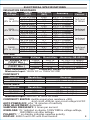
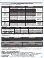
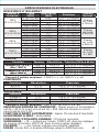
ELECTRICAL SPECIFICATIONS
INSULATION RESISTANCE
Terminal
Voltage Range
(MΩ) Resolution
(MΩ) Accuracy Test
Current
125V
(0% to +20%)
0.125 to 3.999 0.001 ±(2% + 10 digits)
1mA load
@ 125kΩ
4.00 to 39.99 0.01 ±(2% + 10 digits)
40.0 to 399.9 0.1 ±(4% + 5 digits)
400 to 4000 1 ±(5% + 5 digits)
250V
(0% to +20%)
0.250 to 3.999 0.001 ±(2% + 15 digits)
1mA load
@ 250kΩ
4.00 to 39.99 0.01 ±(2% + 10 digits)
40.0 to 399.9 0.1 ±(3% + 5 digits)
400 to 4000 1 ±(4% + 5 digits)
500V
(0% to +20%)
0.500 to 3.999 0.001 ±(2% + 10 digits)
1mA load
@ 500kΩ
4.00 to 39.99 0.01 ±(2% + 10 digits)
40.0 to 399.9 0.1 ±(2% + 5 digits)
400 to 4000 1 ±(4% + 5 digits)
1000V
(0% to +20%)
1.000 to 3.999 0.001 ±(3% + 10 digits)
1mA load
@ 1MΩ
4.00 to 39.99 0.01 ±(2% + 10 digits)
40.0 to 399.9 0.1 ±(2% + 5 digits)
400 to 4000 1 ±(4% + 5 digits)
VOLTAGE
Function Voltage Resolution Accuracy (
50–60 Hz
)
AC Voltage (V AC)
(1000V Max.) <400V ≤0.01V ±(1.0% + 5 digits)
>400V ≤1V ±(1.2% + 5 digits)
DC Voltage (V DC)
(1000V Max.) <400V ≤0.01V ±(0.9% + 3 digits)
>400V ≤1V ±(1.0% + 3 digits)
Input Impedance: 10MΩ Frequency Range: 50 to 60Hz
Maximum Input: 1000V DC or 1000V AC RM
CONTINUITY
Function Resolution Accuracy
40.0Ω 0.1Ω ±(0.5% + 2 digits)
400.0Ω 0.1Ω ±(1.2% + 5 digits)
RESISTANCE
Function Resolution Accuracy
4.000kΩ 1Ω ±(2.5% + 8 digits)
40.00kΩ 10Ω ±(2.8% + 8 digits)
80.0kΩ 100Ω ±(3.0% + 8 digits)
Maximum Input: 300V DC or 300V AC RMS
CONTINUITY BEEPER:
Audible signal when resistance <30Ω,
short circuit >200mA, open circuit voltage 5.5V DC
AUTO POWER-OFF: after 15 minutes of inactivity
ZERO ADJUSTMENT: Automatic
SAMPLING FREQUENCY: 3 times per second
OVERLOAD:
"OL" indicated on display, 1000V RMS in voltage settings,
300V RMS in all other settings
POLARITY: "-" on display indicates negative polarity
DISPLAY: 4000 Count LCD with Dual readout

4
ENGLISH
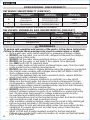
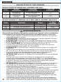
WARNINGS
To ensure safe operation and service of the meter, follow these instructions.
Failure to observe these warnings can result in severe injury or death.
• Before each use, verify meter operation by measuring a known voltage.
• DO NOT use the meter on a circuit with voltages that exceed the category
based rating of this meter.
• DO NOT use the meter during electrical storms or in wet weather.
• DO NOT use the meter or test leads if they appear to be damaged.
• Use ONLY with CAT IV rated test leads.
• Ensure meter leads are fully seated, and keep fingers away from the metal
probe contacts when making measurements.
• DO NOT open the meter to replace batteries while the probes are connected.
• Use caution when working with voltages above 25V AC RMS or 60V DC.
Such voltages pose a shock hazard.
• To avoid false readings that can lead to electrical shock, replace batteries
when a low battery indicator appears.
• DO NOT attempt to measure resistance or continuity on a live circuit.
• Make sure the circuit under test does not include components that can
be damaged by 1000VDC; such devices include power factor correction
capacitors, low voltage mineral insulated cables, electronic light dimmers,
and ballast/starters for fluorescent lamps.
• DO NOT perform insulation resistance testing or earth-bond resistance
testing if voltage is present on parts of an installation or equipment under
test. Circuits under test (except for voltage measurements) must be
de-energized and isolated before connections are made.
• Circuit connections must not be touched during a test. Accidental contact
with conductors could result in electrical shock.
• After insulation resistance testing, make sure the circuit is fully discharged
before removing test leads. LCD should read close to zero volts.
• Always adhere to local and national safety codes. Use personal protective
equipment to prevent shock and arc blast injury where hazardous live
conductors are exposed.
• Meter is IP40 dust & water resistant, except for the test lead jacks.
Following any contact with water, thoroughly dry meter and test lead jacks
prior to subsequent use.
INFLUENCE VARIABLES AND UNCERTAINTIES (EN61557)
Code Variable Range % Within
Range
E1 Position
+/- 90°
<5%
E2 Supply voltage
7.21 to 9.13V
<5%
E3 Temperature 0 to 35°C <5%
OPERATIONAL UNCERTAINITY
INTRINSIC UNCERTAINITY (EN61557)
Code Measurement
Intrinsic Operating
Uncertainty Maximum
Uncertainty*
A
Insulation
Resistance
See ELECTRICAL
SPECIFICATIONS <30%
A
Earth-Bond
Resistance
See ELECTRICAL
SPECIFICATIONS <30%
*Indicates maximun amout allowable by standard

5
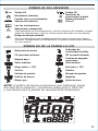
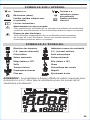
SYMBOLS ON METER
AC Voltage DC Voltage
Resistance (Ohms) Audible Continuity
Fuse (with rating below symbol) Double Insulated Class II
Read Instructions
Warning or Caution
To ensure safe operation and service of this meter, follow all warnings
and instructions detailed in this manual.
Risk of Electrical Shock
Improper use of this meter can lead to risk of electrical shock. Follow
all warnings and instructions detailed in this manual.
SYMBOLS ON LCD
Data Hold Audible Continuity
AC (Alternating Current) DC (Direct Current)
Low Battery Auto Power Off
Maximum Value Minimum Value
Mega (value x 10
6
) kilo (value x 10
3
)
Volts Ohms
Test Voltage Test Lock
Bar Graph Negative
Greater Than Zero Adjustment
NOTE: The bar graph provides a visual indication of the measurement
value, showing voltage for VAC / VDC, and showing resistance for
insulation resistance testing.

6
ENGLISH
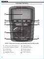
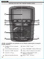
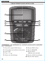
FEATURE DETAILS
1
2
3
5
9
8
10
6 7
4
1. 4000 count LCD Display 6. "ZERO" Button
2. Function Selector Switch 7. "MAX/MIN" Button
3. "COM" Jack 8. "HOLD" Button
4. "V Ω " Jack 9. "LOCK" Button
5. Backlight Button 10. "TEST" Button
NOTE: There are no user-serviceable parts inside meter.

7
FUNCTION BUTTONS
ON/OFF
To Power ON the meter rotate the Function Selector switch
2
from
the OFF setting to any measurement setting. To Power OFF the meter,
rotate the Function Selector switch to the OFF setting.
NOTE: The
meter will automatically power OFF after 15 minutes of inactivity. To
disable auto-power off, press and hold the "HOLD" button
8
while
powering on.
"BACKLIGHT BUTTON
5
Press and hold the Backlight button for more than one second to
turn the backlight on or off. The backlight will automatically turns
off after approximately 3 minutes.
ZERO BUTTON
6
Press the zero button for automatic zero adjustment for voltage
and resistance.
"MAX/MIN" BUTTON
7
When the "MAX/MIN" button is pressed, the meter keeps track of
the minimum and maximum value of the measurement for VAC,
VDC, continuity, and ohms. The first press of the MAX/MIN button
displays the MAX value, the second press displays the MIN value.
To return to normal measuring mode, press and hold the "MAX/
MIN" button for more than one second.
"HOLD" (DATA HOLD) BUTTON
8
Press the "HOLD" button to hold the measurement on the display.
Press again to release the display to return to live measuring (not
for insulation resistance testing).
LOCK BUTTON
9
For hands-free insulation resistance testing, use the Lock button
feature. With the test leads connected to the equipment under test,
press the Lock button for two seconds, and then press the TEST
button to begin the test. The lock icon will appear on the display
and the meter will beep to indicate it is in lock mode. Press the Test
button to end the test.
TEST BUTTON
10
With the test leads connected to the equipment under test, press
and hold the TEST button to begin an insulation resistance test. The
lower-right display will show test voltage, and the main display will
show the resistance.
NOTE: Make sure the circuit under test does not include
components that can be damaged by 1000VDC; such devices
include power factor correction capacitors, low voltage mineral
insulated cables, electronic light dimmers, and ballast/starters for
fluorescent lamps.

8
ENGLISHENGLISH
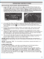
OPERATING INSTRUCTIONS
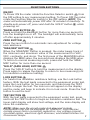
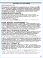
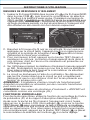
CONNECTING TEST LEADS
Do not test if leads are improperly seated. Results could cause
intermittent display readings. To ensure proper connection, firmly
press leads into the input jack completely.
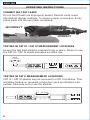
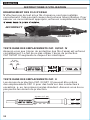
TESTING IN CAT III / CAT IV MEASUREMENT LOCATIONS
Ensure the test lead shield is pressed firmly in place. Failure to use
the CAT III / CAT IV shield increases arc-flash risk.
TESTING IN CAT II MEASUREMENT LOCATIONS
CAT III / CAT IV shields may be removed for CAT II locations. This
will allow testing on recessed conductors such as standard wall
outlets. Take care not to lose the shields.
INCORRECT
CORRECT
0.7" (18 mm)
5/32"
(4 mm)
5/32
(4 mm)
5/32"
(4 mm)

9
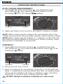
OPERATING INSTRUCTIONS
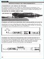
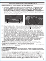
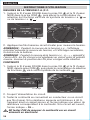
INSULATION RESISTANCE MEASUREMENTS
1. Insert RED test lead into VΩ jack
4
, and BLACK test lead into
COM jack
3
, and rotate the function selector to the desired test
voltage. Choose from 125V, 250V, 500V, or 1000V based on the
compatibility with the device tested.
NOTE: Disconnect the circuit
under test and isolate it from any stray resistance. Insulation test
should only be performed on de-energized circuits.
2. Connect the Red and Black leads to the circuit under test. If there
is a voltage in the circuit, a constant beep will sound and the
Test Voltage symbol will be displayed.
Disconnect the circuit to
proceed.
3. Press and hold the TEST button to begin test. The lower right
display shows test voltage, and the main display shows the
resistance.
4. The measured insulation resistance is displayed on the main
display in MΩ. Allow the reading to stabilize before recording the
measurement. Turning the function switch, at any time during
the insulation test will end the testing process.
5. The circuit will discharge through the meter. Keep the test leads
connected until the circuit is completely discharged and the
lower right display shows near zero volts.
NOTE: Measurements can be adversely affected by impedances
of additional operating circuits connected in parallel or by transient
currents.
NOTE: Overload “OL” for insulation resistance measurements is a
value >4000 MΩ.
LOCK FUNCTION
For hands free testing, use the Lock feature for PI (Polarization
Index) and DAR (Dielectric Absorption Ratio) testing.
With the test leads connected to the equipment under test, press
the "LOCK" button
9
, then press the "TEST" button
10
to begin the
test. The lock icon will appear on the display. The meter will beep
to indicate it is in lock mode. To end the test at any time during the
process, press the "TEST" button
10
, or turn the function switch
2
to any other setting.
Red leadBlack lead

10
OPERATING INSTRUCTIONS
ENGLISH
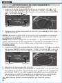
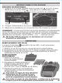
CONTINUITY
1. Insert RED test lead into VΩ jack
4
, and BLACK test lead
into COM jack
3
,
and rotate function selector switch
2
to the
Continuity setting.
2. Remove power from circuit.
3. Test for continuity by connecting conductor or circuit with test
leads. If resistance is measured less than 40Ω, an audible signal
will sound and display will show a resistance value indicating
continuity. If circuit is open, display will show "OL".
DO NOT attempt to measure continuity on a live circuit.
Red leadBlack lead
AC/DC VOLTAGE MEASUREMENTS
1. Insert RED test lead into VΩ jack
4
, and BLACK test lead
into COM jack
3
, and rotate the function selector to the
AC Voltage or DC Voltage setting.
2. Apply test leads to the circuit to be tested to measure voltage.
NOTE: When measuring DC voltage, the main display shows the
voltage measurement, the secondary display shows battery voltage.
NOTE: When measuring DC voltage, if "–" appears on the LCD, the
test leads are being applied to the circuit in reverse polarity. Swap
the position of the leads to correct this.
Red leadBlack lead

11
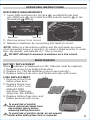
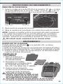
FUSE REPLACEMENT
1. Remove screw from
battery/fuse door.
2. Replace blown fuse
with 6.3 x 31.7 mm,
500mA/1000V
fast-blow 10kA fuse
(Klein Cat. No. 69035).
3. Replace battery/fuse door and
fasten securely with screw.
OPERATING INSTRUCTIONS
MAINTENANCE
BATTERY REPLACEMENT
When indicator is displayed on LCD, batteries must be replaced.
1. Remove screw from battery/fuse door.
2. Replace 6 x 1.5V AA batteries (note proper polarity).
3. Replace battery/fuse door and fasten securely with screw.
To avoid risk of electric
shock, disconnect leads from
any voltage source before
removing battery/fuse door.
To avoid risk of electric shock, do not operate
meter while battery/fuse door is removed.
RESISTANCE MEASUREMENTS
1. Insert RED test lead into VΩ jack
4
, and BLACK test lead
into COM jack
3
,
and rotate function selector switch
2
to the
Resistance setting.
2. Remove power from circuit.
3. Measure resistance by connecting test leads to circuit.
NOTE: When in a Resistance setting and the test leads are open
(not connected across a resistor), or when a failed resistor is under
test, the display will indicate O.L. This is normal.
DO NOT attempt to measure resistance on a live circuit.
Red leadBlack lead

12
ENGLISH
CLEANING
Be sure meter is turned off and wipe with a clean, dry lint-free
cloth.
Do not use abrasive cleaners or solvents.
STORAGE
Remove the batteries when meter is not in use for a prolonged
period of time. Do not expose to high temperatures or
humidity. After a period of storage in extreme conditions
exceeding the limits mentioned in the General Specifications
section, allow the meter to return to normal operating
conditions before using.
FCC & IC COMPLIANCE
See this product’s page at www.kleintools.com for FCC
compliance information
Canada ICES-003 (B) / NMB-003 (B)
WARRANTY
www.kleintools.com/warranty
DISPOSAL / RECYCLE
Do not place equipment and its accessories in the trash.
Items must be properly disposed of in accordance with local
regulations. Please see www.epa.gov/recycle for additional
information.
CUSTOMER SERVICE
KLEIN TOOLS, INC.
450 Bond Street
Lincolnshire, IL 60069
1-800-553-4676
www.kleintools.com

ET600
ESPAÑOL
MANUAL DE INSTRUCCIONES
Probador digital
Probador digital
de resistencia
de aislamiento
• VOLTAJES DE
PRUEBA DE
125V, 250V,
500V Y 1000V
• RANGO DE
RESISTENCIA
DE AISLAMIENTO
HASTA 4000 MΩ
• MIDE 1000V CA/CD
• RESISTENCIA
• CONTINUIDAD
1000 V
1m
80k
Ω
5000573
CAT IV
600V
CAT III
1000V

14
ESPAÑOL
ESPECIFICACIONES GENERALES
El ET600 de Klein Tools es un probador digital con cuatro rangos de
voltaje para la medición de resistencia de aislamiento, y también es
un probador de media cuadrática real (TRMS) que mide voltaje CA/
CD, resistencia eléctrica y continuidad.
• Altitud de funcionamiento: 6562' (2000m)
• Humedad relativa: <80%, sin condensación
• Temperatura de funcionamiento: 14°F a 122°F (-10°C a 50°C)
• Temperatura de almacenamiento: -4°F a 140°F (-30°C a 60°C)
• Precisión: Valores establecidos según una temperatura
ambiente de 65°F a 83°F (18°C a 28°C)
• Coe ciente de temperatura: 0,1 × (precisión indicada) por
cada °C por encima de los 28°C o por debajo de los 18°C, es
necesario realizar correcciones si la temperatura del ambiente de
trabajo se encuentra fuera del rango de precisión de temperatura
• Vida útil de la batería con baterías alcalinas nuevas (EN61557):
Prueba de aislamiento: El probador realiza al menos
137pruebas de aislamiento de 1000VCD en 1MΩ con un ciclo
de servicio de 5s por encendido y 25s por apagado.
Resistencia de puesta a tierra: El probador realiza al menos
265mediciones de resistencia de 1Ω con un ciclo de servicio de
5s por encendido y 25s por apagado.
• Dimensiones: 7,8" × 3,6" × 2,4" (200 × 92 × 62mm)
• Peso: 24,6oz (700g)
• Calibración: precisa durante un año
• Normas: Cumple con: UL 61010-1, 61010-2-030
61010-2-033, 61557-1-2-4.
Certificado según: CSA STD C22.2 n.º61010-1,
61010-2-030, 61010-2-033,
61557-1-2-4.
IECEN 61010-1, 61010-2-030,
61010-2-033, 61326-1,
61557-1-2-4.
• Grado de contaminación: 2
• Precisión: ± (% de la medición + cantidad de dígitos
menossignificativos)
• Protección ante caídas: 3,3' (1m)
• Protección de ingreso: IP40*
*excepto para los conectores de cables de prueba, consulte
lasección ADVERTENCIAS
• Clasi cación de seguridad:
CATIV 600V, CATIII 1000V, clase2,
Doble aislamiento
CATIII: la categoría III de medición es aplicable a los circuitos
de medición y prueba conectados a la distribución de la
instalación de red de bajo voltaje de un edificio.
CATIV: la categoría IV de medición es aplicable a los circuitos
de medición y prueba conectados a la fuente de la instalación
de red de bajo voltaje de un edificio.
• Entorno electromagnético: IEC EN 61326-1. Este equipo cumple
con los requisitos para su uso en entornos electromagnéticos
básicos y controlados, como propiedades residenciales,
establecimientos comerciales e instalaciones de industria ligera.
Especificaciones sujetas a cambios
5000573

15
ESPECIFICACIONES ELÉCTRICAS
RESISTENCIA DE AISLAMIENTO
Voltaje
terminal Rango
(MΩ) Resolu-
ción (MΩ) Precisión Corriente
de prueba
125V
(0% a
+20%)
0,125 a 3,999 0,001
±(2% + 10 dígitos)
Carga de
1mA a
125kΩ
4,00 a 39,99 0,01
± (2% + 10dígitos)
40,0 a 399,9 0,1
± (4% + 5dígitos)
400 a 4000 1
± (5% + 5dígitos)
250V
(0% a
+20%)
0,250 a 3,999 0,001
± (2% + 15dígitos)
Carga de
1mA a
250kΩ
4,00 a 39,99 0,01
± (2% + 10dígitos)
40,0 a 399,9 0,1
± (3% + 5dígitos)
400 a 4000 1
± (4% + 5dígitos)
500V
(0% a
+20%)
0,500 a 3,999 0,001
± (2% + 10dígitos)
Carga de
1mA a
500kΩ
4,00 a 39,99 0,01
± (2% + 10dígitos)
40,0 a 399,9 0,1
± (2% + 5dígitos)
400 a 4000 1
± (4% + 5dígitos)
1000V
(0% a
+20%)
1,000 a 3,999 0,001
± (3% + 10dígitos)
Carga de
1mA a
1MΩ
4,00 a 39,99 0,01
± (2% + 10dígitos)
40,0 a 399,9 0,1
± (2% + 5dígitos)
400 a 4000 1
± (4% + 5dígitos)
VOLTAJE
Función Voltaje Resolución Precisión (50Hz-60Hz)
Voltaje CA (V CA)
(Máx. 1000 V) <400V ≤0,01V ± (1,0% + 5dígitos)
>400V ≤1V ± (1,2% + 5dígitos)
Voltaje CD (V CD)
(Máx. 1000 V) <400V ≤0,01V ± (0,9% + 3dígitos)
<400V ≤1V ± (1,0% + 3dígitos)
Impedancia de entrada: 10MΩ Rango de frecuencia: 50 a 60Hz
Entrada máxima: 1000V CD o 1000V CA RMS
CONTINUIDAD
Función Resolución Precisión
40,0Ω 0,1Ω ± (0,5% + 2dígitos)
400,0Ω 0,1Ω ± (1,2% + 5dígitos)
RESISTENCIA
Función Resolución Precisión
4,000kΩ 1Ω ± (2,5% + 8dígitos)
40,00kΩ 10Ω ± (2,8% + 8dígitos)
80,0kΩ 100Ω ± (3,0% + 8dígitos)
Entrada máxima: 300V CD o 300V CA RMS
INDICADOR SONORO DE CONTINUIDAD:
señal audible cuando la
resistencia <30Ω, cortocircuito >200mA, voltaje de circuito abierto 5,5V DC
APAGADO AUTOMÁTICO: después de 15minutos de inactividad
AJUSTE DE CERO: Automático
FRECUENCIA DE MUESTREO: 3 veces por segundo
SOBRECARGA:
se indica “OL” en pantalla, 1000V RMS en posiciones
de voltaje, 300V RMS en las demás posiciones
POLARIDAD: “-” en pantalla indica polaridad negativa
PANTALLA: LCD con recuento de 4000 y valores dobles

16
ESPAÑOL
ADVERTENCIAS
Para garantizar un funcionamiento y servicio seguros del medidor, siga
estas instrucciones. El incumplimiento de estas advertencias puede
provocar lesiones graves o la muerte.
• Antes de cada uso, verifique el funcionamiento del medidor midiendo un voltaje.
• NO utilice el medidor en un circuito con voltajes que excedan la clasificación
correspondiente a la categoría de este medidor.
• NO utilice el medidor durante tormentas eléctricas o en climahúmedo.
• NO utilice el medidor o los cables de prueba si en apariencia están dañados.
• Utilice el medidor ÚNICAMENTE con cables de prueba con clasificación CAT IV.
• Asegúrese de que los cables del medidor estén correctamente colocados y mantenga
los dedos lejos de los contactos de la sonda de metal al realizar las mediciones.
• NO abra el medidor para reemplazar las baterías mientras lassondas están conectadas.
• Proceda con precaución cuando trabaje con voltajes superiores a 25VCA RMS o
60VCD. Esos voltajes implican un riesgo de choque eléctrico.
• Para evitar lecturas falsas que puedan provocar choques eléctricos, reemplace las
baterías cuando aparezca el indicador de batería baja.
• NO intente medir resistencia o continuidad en un circuito activo.
• Asegúrese de que el circuito que desea probar no incluya componentes que puedan
dañarse con 1000V CD; dichos dispositivos incluyen capacitores para la corrección
del factor de potencia, cables con aislamiento mineral para bajo voltaje, atenuadores
de luz electrónicos y balastos/encendedores de lámparas fluorescentes.
• NO realice pruebas de resistencia de aislamiento o pruebas de resistencia de puesta
a tierra si el voltaje está presente en piezas de una instalación o equipo que desea
probar. Los circuitos que desea probar (excepto para mediciones de voltaje) deben
estar desenergizados y aislados antes de realizar las conexiones.
• Las conexiones de circuitos no deben tocarse durante una prueba. El contacto
accidental con conductores puede causar choque eléctrico.
• Después de la prueba de resistencia de aislamiento, asegúrese de que el circuito esté
completamente descargado antes de retirar los cables de prueba. Las lecturas del
LCD deben ser cercanas a los cero voltios.
• Cumpla siempre con los códigos de seguridad locales y nacionales. Utilice equipo de
protección personal para prevenir lesiones por choque y arco eléctrico en los lugares
donde haya conductores activos peligrosos expuestos.
• El medidor cuenta con calificación IP40 resistente al agua y al polvo, excepto los
conectores de los cables de prueba. Después del contacto con el agua, seque
minuciosamente el medidor y los conectores de cables de prueba antes de utilizarlo
nuevamente.
VARIABLES DE INFLUENCIA E INCERTIDUMBRES (EN61557)
Código Variable Rango % dentro del
rango
E1 Posición
+/- 90°
<5%
E2 Voltaje de suministro
7,21 a 9,13V
<5%
E3 Temperatura 0 a 35°C <5%
INCERTIDUMBRE DE FUNCIONAMIENTO
INCERTIDUMBRE INTRÍNSECA (EN61557)
Código Medición
intrínseca Incertidumbre de
funcionamiento Incertidumbre
máxima*
A
Resistencia de
aislamiento
Vea las ESPECIFICACIONES
ELÉCTRICAS <30%
A
Resistencia de
puesta a tierra
Vea las ESPECIFICACIONES
ELÉCTRICAS <30%
*Indica la cantidad máxima permitida por estándar

17
SÍMBOLOS DEL MEDIDOR
Voltaje CA Voltaje CD
Resistencia (ohmios) Indicador de
continuidad audible
Fusible (con su clasi cación
debajo del símbolo) Doble aislamiento
Clase II
Lea las instrucciones
Advertencia o precaución
Para garantizar un funcionamiento y servicio seguros del medidor, respete
todas las advertencias y siga las instrucciones descritas en este manual.
Riesgo de choque eléctrico
El uso incorrecto de este medidor puede dar lugar a riesgos de choque
eléctrico. Respete todas las advertencias y siga las instrucciones descritas
en este manual.
SÍMBOLOS DE LA PANTALLA LCD
Retención de datos Indicador de
continuidad audible
CA (corriente alterna) CD (corriente directa)
Batería baja Función de apagado
automático
Valor máximo Valor mínimo
Mega (valor × 10
6
)kilo (valor × 10
3
)
Voltios Ohmios
Voltaje de prueba Bloqueo de prueba
Grá co de barras Negativo
Mayor que Ajuste de cero
NOTA: el gráfico de barras proporciona una indicación visual
del valor de la medición, mostrando voltaje para VCA/VCD,
yresistencia para la prueba de resistencia de aislamiento.

18
ESPAÑOL
DETALLES DE LAS CARACTERÍSTICAS
1
2
3
5
9
8
10
6 7
4
1. Pantalla LCD con recuento
de 4000 6.
Botón “ZERO” (Cero)
2. Perilla selectora de función 7.
Botón “MAX/MIN” (Máximo/Mínimo)
3. Conector “COM” (Común) 8.
Botón “HOLD” (Retención de datos)
4. Conector “V Ω ”9. Botón “CONTINUOUS LOCK”
(Bloqueo continuo)
5. Botón de retroiluminación 10.
Botón “TEST” (Probar)
NOTA: el medidor no contiene en su interior piezas que el usuario
pueda reparar.

19
BOTONES DE FUNCIONES
ENCENDIDO/APAGADO
Para encender el medidor, gire la perilla selectora de función
2
de
la posición OFF (Apagado) a cualquier posición de medición. Para
apagar el medidor, gire la perilla selectora de función a la posición
“OFF” (Apagado).
NOTA: El medidor se apagará automáticamente
después de 15minutos de inactividad. Para desactivar la función
de apagado automático, mantenga presionado el botón "HOLD"
(Retener)
8
durante el encendido.
BOTÓN DE RETROILUMINACIÓN
5
Mantenga presionado el botón de retroiluminación durante
másde un segundo para encender o apagar la retroiluminación.
La retroiluminación se apagará automáticamente al cabo de
aproximadamente 3minutos.
BOTÓN “ZERO” (CERO)
6
Presione el Botón “ZERO” (Cero) para ajustar automáticamente
acero para voltaje y resistencia.
BOTÓN “MAX/MIN” (MÁXIMO/MÍNIMO)
7
Cuando se presiona el botón “MAX/MIN” (“Máximo/Mínimo”), el
medidor registra los valores mínimo y máximo de la medición de VCA,
VCD, continuidad y ohmios. Si se presiona una vez el botón “MAX/
MIN” (“Máximo/Mínimo”), se mostrará en pantalla el valor máximo;
si se lo presiona una segunda vez, se visualizará el valor mínimo. Para
volver al modo de medición normal, mantenga presionado el botón
“MAX/MIN” (“Máximo/Mínimo”) durante más de un segundo.
BOTÓN “HOLD” (RETENCIÓN DE DATOS)
8
Presione el botón “HOLD” (Retención de datos) para retener la medición
en la pantalla. Vuelva a presionarlo para que la pantalla regrese a la
medición en curso (no para la prueba de resistencia de aislamiento).
BOTÓN “CONTINUOUS LOCK” (BLOQUEO CONTINUO)
9
Para probar la resistencia de aislamiento con las manos libres, use la
función del botón “CONTINUOUS LOCK” (Bloqueo continuo). Con los
cables de prueba conectados al equipo que se desea probar, presione
el botón “CONTINUOUS LOCK” (Bloqueo continuo) por dos segundos,
y luego presione el botón “TEST” (Probar) para iniciar la prueba. El
ícono de bloqueo aparecerá en la pantalla y el medidor emitirá un pitido
para indicar que está en modo bloqueo. Presione el botón “TEST”
(Probar) para finalizar la prueba.
BOTÓN “TEST” (PROBAR)
10
Con los cables de prueba conectados al equipo que se desea
probar, mantenga presionado el botón “TEST” (Probar) para iniciar
una prueba de resistencia de aislamiento. El voltaje de la prueba se
mostrará en el lado inferior derecho de la pantalla, y la resistencia,
en el centro de la pantalla.
NOTA: Asegúrese de que el circuito que desea probar no incluya
componentes que puedan dañarse con 1000V CD; dichos dispositivos
incluyen capacitores para la corrección del factor de potencia,
cables con aislamiento mineral para bajo voltaje, atenuadores de luz
electrónicos y balastos/encendedores de lámparas fluorescentes.

20
ENGLISHESPAÑOL
INSTRUCCIONES DE FUNCIONAMIENTO
CONEXIÓN DE LOS CABLES DE PRUEBA
No realice pruebas si los cables no están bien conectados. Los
resultados podrían generar lecturas intermitentes en pantalla. Para
garantizar una buena conexión, presione los cables firmemente en
el conector de entrada hasta el final.
PRUEBAS EN PUNTOS DE MEDICIÓN CON CLASIFICACIÓN CAT III/CAT IV
Asegúrese de que el blindaje del cable de prueba esté firmemente
colocado en su lugar. No utilizar el blindaje CAT III/CAT IV aumenta
el riesgo de que se produzca un arco eléctrico.
PRUEBAS EN PUNTOS DE MEDICIÓN CON CLASIFICACIÓN CATII
Es posible retirar blindajes CATIII/CATIV para realizar mediciones
en los puntos con clasificación CATII. Esto permite efectuar
pruebas en conductores empotrados, como tomacorrientes
depared estándar. Procure no perder los blindajes.
el conector de entrada hasta el final.
INCORRECTO
CORRECTO
0,7" (18 mm)
5/32"
(4 mm)
5/32
(4 mm)
5/32"
(4 mm)
La page est en cours de chargement...
La page est en cours de chargement...
La page est en cours de chargement...
La page est en cours de chargement...
La page est en cours de chargement...
La page est en cours de chargement...
La page est en cours de chargement...
La page est en cours de chargement...
La page est en cours de chargement...
La page est en cours de chargement...
La page est en cours de chargement...
La page est en cours de chargement...
La page est en cours de chargement...
La page est en cours de chargement...
La page est en cours de chargement...
La page est en cours de chargement...
-
 1
1
-
 2
2
-
 3
3
-
 4
4
-
 5
5
-
 6
6
-
 7
7
-
 8
8
-
 9
9
-
 10
10
-
 11
11
-
 12
12
-
 13
13
-
 14
14
-
 15
15
-
 16
16
-
 17
17
-
 18
18
-
 19
19
-
 20
20
-
 21
21
-
 22
22
-
 23
23
-
 24
24
-
 25
25
-
 26
26
-
 27
27
-
 28
28
-
 29
29
-
 30
30
-
 31
31
-
 32
32
-
 33
33
-
 34
34
-
 35
35
-
 36
36


Klein Tools ET600 Manuel utilisateur
- Catégorie
- Testeurs de réseau câblé
- Taper
- Manuel utilisateur
dans d''autres langues
- español: Klein Tools ET600 Manual de usuario

