Nilfisk-Advance 56212000 Instructions For Use Manual
- Catégorie
- Machine à plancher
- Taper
- Instructions For Use Manual
Ce manuel convient également à


A- 2 - FORM NO. 56041544 - AquaMAX™ / AX 650
A-2 / ENGLISH
TABLE OF CONTENTS
Page
Introduction .................................................................................................................................................................... A-3
Parts and Service .......................................................................................................................................................... A-3
Nameplate ..................................................................................................................................................................... A-3
Uncrating the Machine ................................................................................................................................................... A-3
Important Safety Instructions ......................................................................................................................................... A-4
Know Your Machine .................................................................................................................................................... A-5-6
Functional Description of Controls ................................................................................................................................. A-7
Preparing the Machine for Use
Installing the Batteries ................................................................................................................................................... A-8
Filling the Solution Tank ................................................................................................................................................. A-8
Pre-Spraying the Carpet ................................................................................................................................................ A-8
Plan for Cleaning ........................................................................................................................................................... A-8
Operating the Machine .................................................................................................................................................. A-9
Using Attachments ......................................................................................................................................................... A-9
After Using the Machine .............................................................................................................................................. A-10
Maintenance Schedule ................................................................................................................................................ A-10
Maintenance
Pick-Up Tool Maintenance ............................................................................................................................................A-11
Spray Nozzle Maintenance ...........................................................................................................................................A-11
Lubricating the Machine ...............................................................................................................................................A-11
Cleaning the Vacuum Motor Filters ..............................................................................................................................A-11
Adjusting the Brush Height ...........................................................................................................................................A-11
Power Brush Maintenance ...........................................................................................................................................A-11
Removing the Brush .....................................................................................................................................................A-11
Charging the Batteries ................................................................................................................................................. A-12
Checking the Battery Water Level ............................................................................................................................... A-12
Battery Maintenance .................................................................................................................................................... A-12
Battery Testing ............................................................................................................................................................. A-12
Troubleshooting
Control Circuit Circuit Breaker ..................................................................................................................................... A-13
Wheel Drive Circuit Breaker ........................................................................................................................................ A-13
Brush Drive Circuit Breaker ......................................................................................................................................... A-13
Vacuum Motor Circuit Breaker ..................................................................................................................................... A-13
Technical Specifications .............................................................................................................................................. A-13

FORM NO. 56041544 - AquaMAX™ / AX 650 - A-3
ENGLISH / A-3
INTRODUCTION
This manual will help you get the most from your Nilfisk-Advance AquaMAX™ / AX 650. Read it thoroughly before operating the machine.
Note: Bold numbers in parentheses indicate an item illustrated on pages A-5 – A-6.
This product is intended for commercial use only.
PARTS AND SERVICE
Repairs, when required, should be performed by your Authorized Nilfisk-Advance Service Center, who employs factory trained service personnel,
and maintains an inventory of Nilfisk-Advance original replacement parts and accessories.
Call the NILFISK-ADVANCE DEALER named below for repair parts or service. Please specify the Model and Serial Number when discussing
your machine.
(Dealer, affix service sticker here.)
NAME PLATE
The Model Number and Serial Number of your machine are shown on the Nameplate on the machine. This information is needed when ordering
repair parts for the machine. Use the space below to note the Model Number and Serial Number of your machine for future reference.
MODEL NUMBER
SERIAL NUMBER
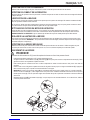
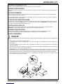
UNCRATE THE MACHINE
When the machine is delivered, carefully inspect the shipping carton and the machine for damage. If damage is evident, save the shipping carton
so that it can be inspected. Contact the Nilfisk-Advance Customer Service Department immediately to file a freight damage claim.

A- 4 - FORM NO. 56041544 - AquaMAX™ / AX 650
A-4 / ENGLISH
IMPORTANT SAFETY INSTRUCTIONS
This machine is only suitable for commercial use, for example in hotels, schools, hospitals, factories, shops and offices other than
normal residential housekeeping purposes.
When using an electrical appliance, basic precautions should always be followed, including the following:
Read all instructions before using.
WARNING!
To reduce risk of fire, electric shock, or injury:
• This machine should only be used by properly trained and authorized persons.
• Keep sparks, flame and smoking materials away from batteries. Explosive gases are vented during normal operation.
• Charging the batteries produces highly explosive hydrogen gas. Charge batteries only in well-ventilated areas, away from
open flame. Do not smoke while charging the batteries.
• Remove all jewelry when working near electrical components.
• Turn the key switch off (O) and disconnect the batteries before servicing electrical components.
• Never work under a machine without safety blocks or stands to support the machine.
• Do not dispense flammable cleaning agents, operate the machine on or near these agents, or operate in areas where flammable
liquids exist.
• Do not clean this machine with a pressure washer.
• Do not operate this machine on ramps or inclines of more than a 2 percent gradient.
• Only use the brushes provided with the appliance or those specified in the instruction manual. The use of other brushes may
impair safety.
CAUTION!
• This machine is not approved for use on public paths or roads.
• This machine is not suitable for picking up hazardous dust.
• When operating this machine, ensure that third parties, particularly children, are not endangered.
• Before performing any service function, carefully read all instructions pertaining to that function.
• Do not leave the machine unattended without first turning the key switch off (O), removing the key and securing the machi-
ne.
• Turn the key switch off (O) and remove the key, before changing the brushes, and before opening any access panels.
• Take precautions to prevent hair, jewelry, or loose clothing from becoming caught in moving parts.
• Use caution when moving this machine in below freezing temperature conditions. Any water in the solution or recovery tanks
or in the hose lines could freeze.
• The batteries must be removed from the machine before the machine is scrapped. The disposal of the batteries should be
safely done in accordance with your local environmental regulations.
• Do not use on surfaces having a gradient exceeding that marked on the machine.
• All doors and covers are to be positioned as indicated in the instruction manual before using the machine.
SAVE THESE INSTRUCTIONS

FORM NO. 56041544 - AquaMAX™ / AX 650 - A-5
ENGLISH / A-5
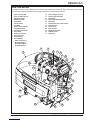
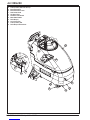
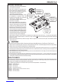
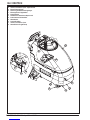
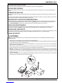
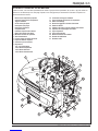
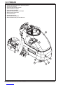
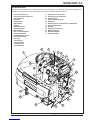
KNOW YOUR MACHINE
As you read this manual, you will occasionally run across a bold number in parentheses - example: (2). These numbers refer to an item on this
page. Refer back to this page whenever necessary to pinpoint the location of an item mentioned in the text.
1 Upper (recovery) Tank
2 Recovery Tank Dome Lid
3 Battery Fuel Gauge
4 Master Key Switch
5 Pump Switch
6 Vacuum Switch
7 Hour Meter
8 Brush Pressure Indicator
9 Speed Control Knob
10 Operator Control Handle
11 Drive Paddle
12 Brush Deck Lift Lever
13 Upper Tank Latch
14 Accessory Port
15 Circuit Breakers
6 Amp-Control Circuit
40 Amp-Vac Motors
20 Amp-Brush Motor
20 Amp-Drive Motor
16 Battery Charger Connector
17 Recovery Tank Drain Hose
18 Pick-Up Tool
19 Brush Height Adjustment Knob
20 Brush Deck
21 Solution Drain Hose / Level Indicator
22 Solution Fill Cap
23 Vacuum Hose
24 Recovery Hose
25 Nozzle Selector Knob
26 Stabilizer Caster
27 Rear Caster

A- 6 - FORM NO. 56041544 - AquaMAX™ / AX 650
A-6 / ENGLISH
28 Lower (solution) Tank Flush-Out Cap
29 Brush Access Door
30 Brush Access Door Latch
31 Deck Release Knob
32 Vac Motor Filters
33 Automatic Float Shut-Off
34 Waste Water Bladder
35 Roller Bumper
36 InLine Pump Filter
37 Lower (solution) Tank
38 Roller Bumper Release Knob

FORM NO. 56041544 - AquaMAX™ / AX 650 - A-7
ENGLISH / A-7
FUNCTIONAL DESCRIPTION OF CONTROLS:
Upper (recovery) Tank (1) - Waste water recovered from carpet is deposited here inside of a bladder (34). Area outside of waste water bladder (34) is utilized for extra clean
solution capacity. The batteries and Vac Motor Filters (32) can be accessed by opening this tank to the side.
Recovery Tank Dome Lid (2) - Point of entry for waste water into bladder. Also houses Automatic Float Shut-Off (33) which shuts off vacuum port to vac motors when bladder is
full. Remove this lid to rinse out the waste water bladder or to fill the solution tank.
Battery Fuel Gauge (3) - Shows current state of charge of batteries. A double-flashing light indicates low batteries, charge immediately. NOTE: When the battery fuel gauge
shows double-flashing lights, all systems shut down except the wheel drive system.
Master Key Switch (4) - Main power switch.
Pump Switch (5) - This button is used to select the mode of operation for the solution system. There are 3 modes of operation for this system. The modes are AUTO / OFF / ON.
Following is a description of each mode.
AUTO MODE: In this mode the solution flow will be turned ON whenever the brush is lowered and the machine is moving forward. The solution flow will be turned off when the
machine is not moving, moving in reverse or the brush is raised.
OFF MODE: In this mode the solution flow is turned off.
ON MODE: This mode is for accessory use. The pump is ON at all times as long as the Master Key Switch (4) is ON.
Vacuum Switch (6) - This button is used to select the mode of operation for the vacuum system. There are 3 modes of operation for this system. These modes are AUTO / OFF
/ ON. Following is a description of each mode.
AUTO MODE: In this mode the vacuum will be turned ON whenever the brush is lowered and the Master Key Switch (4) is ON. While in this mode the vacuum will remain on for
10 seconds after the brush is raised.
OFF MODE: In this mode the vacuum is off.
ON MODE: This mode is for accessory use. The vacuum is ON at all times as long as the Master Key Switch (4) is ON.
Hourmeter (7) - Displays number of hours machine has been used. NOTE: The hourmeter only runs when the vac motors are running.
Brush Pressure Indicator (8) - This meter should be reading 8-15 amps (green zone), readings outside this range indicate the need for brush height adjustment.
Speed Control Knob (9) - Turn this knob clockwise to increase maximum speed range and counter-clockwise to decrease maximum speed range.
Operator Control Handle (10) - Operator holds onto this handle to maneuver the machine.
Drive Paddle (11) - The operator can make the machine go forward by pushing forward on it, or reverse by pulling backward on it. The speed is variable depending on how far
forward or backward the paddle is moved. The brush and pump will operate when the brush deck is in the “DOWN” position and the drive paddle is engaged in either direction,
both will stop 1 second after the drive paddle is released. NOTE: The pump does not run when the drive paddle is in the reverse position.
Brush Deck Lift Lever (12) - This lever is used to raise or lower the brush deck. Both pump and vacuum turn ON when the brush deck is lowered and turn OFF when it is raised
if their switches are in the AUTO position. NOTE: Machine must be moving forward to activate pump, forward or reverse to activate brush. Vacuum system shuts off 10 seconds
after raising the brush deck.
Upper Tank Latch (13) - This latch is used to secure the Upper Tank (1) to the machine to prevent the tank from opening while operating the machine since the Operator Control
Handle (10) is mounted to the upper tank.
Accessory Port (14) - This is used to connect external accessories.
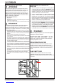
Circuit Breakers (15)
6 Amp-Control Circuit - Provides overload protection. If it trips, it will pop out. To reset, wait one minute and press the button back in. If any breaker trips repeatedly, have
the machine serviced.
40 Amp-Vac Motors - Provides overload protection to machine’s vacuum motors. If it trips, it will pop out. To reset, wait one minute and press the button back in. If any breaker
trips repeatedly, have the machine serviced.
20 Amp-Brush Motor - Provides overload protection to machine’s brush motor. If it trips, it will pop out. To reset, wait one minute and press the button back in. If any breaker
trips repeatedly, have the machine serviced.
20 Amp-Drive Motor - Provides overload protection to machine’s wheel drive motor. If it trips, it will pop out. To reset, wait one minute and press the button back in. If any
breaker trips repeatedly, have the machine serviced.
Battery Charger Connector (16) - Plug battery charger into this port to charge batteries.
Recovery Tank Drain Hose (17) - Used to empty the recovery tank. NOTE: Hold the end of the hose above the water level in the tank to avoid sudden, uncontrolled flow of waste
water when removing plug.
Pick-Up Tool (18) - Removes excess solution from carpet after scrubbing.
Brush Height Adjustment Knob (19) - Used to adjust the height of the brush deck. Turn clockwise to raise the brush deck and counter-clockwise to lower the brush deck. NOTE:
Use this adjustment knob in conjunction with the Brush Pressure Indicator (8).
Brush Deck (20) - Contains brush drive motor and brush.
Solution Drain Hose/Level Indicator (21) - Used to empty the solution tank and show current level of solution in tank, graduations are marked on the side of the machine next
to the hose.
Solution Fill Cap (22) - The solution tank can be filled at this location or through the front opening at the top of the Upper Tank after removing the Recovery Tank Dome Lid.
Vacuum Hose (23) - This hose connects to the vac motor assembly in order to create a vacuum inside the waste water bladder.
Recovery Hose (24) - This hose connects between the Pick-Up Tools (18) and the Recovery Tank Dome Lid (2) to bring waste water into the bladder.
Nozzle Selector Knob (25) - Use this knob to select either Maintenance Mode or Restoration Mode. NOTE: The Speed Control Knob (9) has two corresponding settings.
Maintenance Mode: Lower solution flow, higher travel speed. Recommended for frequent surface cleaning.
Restoration Mode: Higher solution flow, lower travel speed. Recommended for less frequent deep cleaning.
Stabilizer Caster (26) - This caster provides stability to the unit when opening the Upper (recovery) Tank (1).
Rear Caster (27) - These two casters along with the main drive wheel bear the weight of the machine and allow easy maneuvering around corners.
Lower (solution) Tank Flush-Out Cap (28) - This cap allows access to the Lower (solution) Tank for the purpose of flushing with clean water.
Brush Access Door (29) - The power brush can be removed or installed via this door.
Brush Access Door Latch (30) - Unsnap this latch to allow access to the power brush.
Deck Release Knob (31) - Pull this knob out and slide Brush Deck out to the right until it latches in place. This allows cleaning under shelves, railings, etc.
Vac Motor Filters (32) - Intake filters for vacuum motor assembly. Refer to the maintenance chart for maintenance intervals.
Automatic Float Shut-Off (33) - The float shut-off blocks the vacuum port when the Waste Water Bladder (34) is full. You can tell when the float closes by the sudden change in
sound of the vacuum motors. When the float closes, the recovery tank must be emptied. The machine will not pickup water with the float closed.
Waste Water Bladder (34) - Contains waste water as it is recovered from carpet. Total capacity of 30 gallons (113.5 Liters).
Roller Bumper (35) - This is a 3 position slide-out bumper to aid in machine maneuvering along walls.
InLine Pump Filter (36) - This filter removes debris from the solution prior to flowing through the pump. Drain solution prior to cleaning this filter.
Lower (solution) Tank (37) - This tank in combination with the upper tank brings total solution capacity to 40 gallons (151.4 Liters).
Roller Bumper Release Knob (38) - This knob allows you to slide the roller bumper out or in to limit how close the machine travels to the wall.

A-8 - FORM NO. 56041544 - AquaMAX™ / AX 650
A-8 / ENGLISH
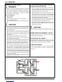
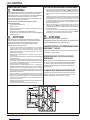
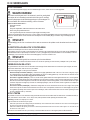
INSTALLING THE BATTERIES
WARNING!
Use extreme caution when working with batteries. Sulfuric acid
in batteries can cause severe injury if allowed to contact the skin
or eyes. Explosive hydrogen gas is vented from the batteries
through openings in the battery caps. This gas can be ignited
by any electrical arc, spark or flame.
When Servicing Batteries...
* Remove all jewelry
* Do not smoke
* Wear safety glasses, rubber gloves and a rubber apron
* Work in a well-ventilated area
* Do not allow tools to touch more than one battery terminal at a
time
CAUTION!
Electrical components in this machine can be severely damaged
if the batteries are not installed and connected properly. Batteries
should be installed by Nilfisk-Advance, a qualified electrician, or
the battery manufacturer.
1 Remove the batteries from their shipping crate and carefully inspect
them for cracks or other damage. If damage is evident, contact
the carrier that delivered them or the battery manufacturer to file
a damage claim.
2 Turn the Master Key Switch (4) OFF and remove the key.
3 Open the Upper (recovery) Tank (1). Remove the battery cables
from inside the battery compartment.
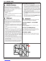
4 Your machine comes from the factory with enough battery cables
to install six 6 volt batteries. Carefully lift the batteries into the
battery compartment and arrange them exactly as shown. Secure
the batteries as close to the back of the machine as possible.
5 The terminals on the battery cables are marked „+“ for positive
and „–“ for negative. Install the battery cables as shown, with the
terminals marked „+“ on the positive battery terminals and the ter-
minals marked „–“ on the negative terminals. Position the cables
so the battery caps can be easily removed for battery service.
6 Carefully tighten the nut in each battery terminal until the terminal
will not turn on the battery post. Then tighten the nut one additional
turn. Do not over-tighten the terminals, or they will be very difficult
to remove for future service.
7 Coat the terminals and posts with spray-on battery terminal coating
(available at most auto parts stores).
8 Put one of the black rubber boots over each of the terminals.
FILLING THE SOLUTION TANK
1 Either remove the Solution Fill Cap (22) or the Recovery Tank
Dome Lid (2). NOTE: When filling the solution tank via the top
of the Upper Tank (1), make sure that you pour the solution into
the opening closest to the front of the machine.
2 Read the dilution instructions on the chemical container. Then
figure the proper amount of chemical to mix with 40 gallons
(151.41 liters) of water. For best results, use the Nilfisk-Advance
CarpeTeam™ Extraction Cleaner chemical specially formulated
for use with Nilfisk-Advance carpet extractors.
3 Pour the chemical into the solution tank and fill the tank with warm
water. NOTE: Watch the Solution Level Indicator (21) as you fill
the tank. When it reaches the 40 gallon mark, stop.
4 Put the Solution Filler Cap (22) or the Recovery Tank Dome Lid
(2) back on the machine. NOTE: Make sure the Dome Lid is
properly seated on the tank.
CAUTION!
Use low-sudsing, liquid detergents designed for carpet extrac-
tion.
BEFORE USING THE AQUAMAX™ / AX 650
Thoroughly vacuum the carpet to be cleaned before using the Aqua-
MAX™ / AX 650 automatic extractor.
PRE-SPRAYING THE CARPET
Pre-spray spots and heavy traffic areas before extracting. Use a hand-
held bottle sprayer or a pressurized “Hudson” type sprayer. Mix the
pre-spray according to the chemical manufacturer’s directions.
PLAN FOR CLEANING
Before you begin extracting, look at the area to be cleaned and plan
your work. Divide the space into sections. Overlap each pass 2
inches (5 cm).

FORM NO. 56041544 - AquaMAX™ / AX 650 - A-9
ENGLISH / A-9
OPERATING THE MACHINE
1 Follow the instructions in the Preparing the Machine
for Use section of this manual.
2 Make sure the Solution Fill Cap (22) and the
Recovery Tank Dome Lid (2) are firmly in place.
3 Make sure the Pump Switch (5) and the Vacuum
Switch (6) are both in the AUTO position.
4 Turn the Master Key Switch (4) ON.
5 Adjust the Nozzle Selector Knob (25) to either
the “maintenance” or “restoration” mode. Set
the Speed Control Knob (9) to the corresponding
“maintenance” or “restoration” setting.
6 Lower the Brush Deck (20) to the floor using the
Brush Deck Lift Lever (12).
7 When the Drive Paddle (11) is in the neutral po-
sition, the brush does not run and solution is not
dispensed. Grip the Operator Control Handle (10)
and push the Drive Paddle (11) forward to start
the brush motor and the solution, and to move the
machine forward. For best results, move the ma-
chine at full speed assuming that step 5 has been
completed. Pull the Drive Paddle (11) backward to
move the machine in reverse. The brush will turn
in the opposite direction while moving the machine
in reverse, and solution will not be dispensed.
8 Begin cleaning by driving the machine forward in a straight line and overlap each pass by 2 inches (5 cm). Turn the Pump Switch (5) OFF
prior to turns to ensure complete extraction of solution from carpet. Guide the right side of the machine along the wall when cleaning the
perimeter of the room.
9 Watch the fluid entering the Recovery Tank Dome Lid (2). If there is a large amount of suds in the recovery tank, add a defoamer chemical
to the recovery tank.
CAUTION!
Empty the recovery tank before the fluid or foam enters the Vacuum Hose (23) at the rear of the Recovery Tank Dome Lid.
If there is little or no fluid entering the recovery tank, check the Solution Drain Hose / Level Indicator (21), the solution tank may be empty.
Refill the solution tank with water and the proper ratio of cleaning chemical.
10 The recovery tank has an Automatic Float Shut-Off (33) to block the vacuum system when the recovery tank is full. You can tell when the
float closes by the sudden change in the sound of the vacuum motors. When the float closes, the recovery tank must be emptied. The
machine will not pick up water with the float closed.
11 When the operator wants to stop cleaning or the recovery tank is full, raise the Brush Deck Lift Lever (12). This will automatically stop the
brush, pump and vacuum motors.
12 Drive the machine to a designated waste water “DISPOSAL SITE” and empty the recovery tank. To empty, pull the Drain Hose (17) from
it’s rear storage area, then remove the plug (hold the end of the hose above the water level in the tank to avoid sudden, uncontrolled flow
of waste water). Refill the solution tank and continue cleaning.
USING ATTACHMENTS
To use accessory tools, attach the accessory recovery hose to the front port of the Recovery Tank Dome Lid (2). Attach the accessory solution
hose to the Accessory Port (14). Connect the other ends of the hoses to the accessory tool. When using accessory tools, raise the Brush Deck
(20) and place the Pump (5) and Vacuum (6) Switches in the ON position.
See your Nilfisk-Advance Distributor for accessories that may be used with the AquaMAX™ / AX 650 including:
• 56250185 PowerHead™ 12
• 56204223 Drag Tool SS 4 Ft
• 56204224 Hand Tool SS
• 56249318 Scrub & Vac Hose 15 Ft
• 56801000 Aqua Kit (Includes PN 56800385, 56800390 & 56249318)
• 56800390 Drag Tool (Plastic)
• 56800385 Hand Tool (Plastic)

A- 10 - FORM NO. 56041544 - AquaMAX™ / AX 650
A-10 / ENGLISH
AFTER USING THE MACHINE
1 Raise the Brush Deck (12).
2 Turn the Master Key Switch (4) OFF.
3 To empty the solution tank, pull the Solution Drain Hose (21) off the elbow Direct the hose to a designated waste water “DISPOSAL SITE”
and remove the plug. Rinse the tank with clean water. Inspect the solution hoses; replace if kinked or damaged.
4 To empty the recovery tank, take the Recovery Drain Hose (17) off its hanger. Direct the hose to a designated waste water “DISPOSAL
SITE” and remove the plug (hold the end of the hose above the water level in the tank to avoid sudden, uncontrolled flow of waste water).
Rinse the tank with clean water. Inspect the recovery and vacuum hoses; replace if kinked or damaged.
5 Remove the Brush (29), rinse with warm water and remove any built-up string, hair or carpet fibers.
6 Disconnect the Recovery Hose (24) from the Recovery Tank Dome Lid (2) and flush with warm water to wash any debris out of the Recovery
Hose / Pick-Up Tool Assembly. NOTE: Make sure that you have disconnected the correct hose, if you run water into the vac motors they
will be damaged.
7 Wipe the machine with a damp cloth. Do not use abrasive chemicals or solvents.
8 Perform any required maintenance before storage.
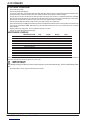
MAINTENANCE SCHEDULE
MAINTENANCE ITEM Daily Weekly Monthly Yearly
Charge Batteries •
Check / Clean Power Brush •
Check / Clean Tanks & Hoses •
Check / Clean Vacuum Shut-Off Float •
Check / Clean Vacuum Motor Filters •
Clean Pick-Up Tools •
Clean Spray Nozzles •
Check Each Battery Cell(s) Water Level •
Inspect Brush Deck Skirt •
Inspect & Clean InLine Pump Filter •
Lubricate the Machine •
*Check Carbon Brushes •
* Have a Nilfisk-Advance service technician check the vacuum motor carbon brushes once a year or after 300 operating hours. The brush and
drive motor carbon brushes check every 500 hours or once a year.
IMPORTANT!
Motor damage resulting from failure to service the carbon brushes is not covered under warranty. See the Limited Warranty State-
ment.
9 Store the machine in a clean, dry place with the tank dome lid open.

FORM NO. 56041544 - AquaMAX™ / AX 650 - A-11
ENGLISH / A-11
PICK-UP TOOL MAINTENANCE
Check the pick-up tools daily. Remove any built-up string, hair or carpet fibers.
SPRAY NOZZLE MAINTENANCE
Remove the spray nozzles once a week. Soak the nozzles overnight in a vinegar and water solution to remove chemical deposits.
LUBRICATING THE MACHINE
Once a month (or every 30 hours), lubricate all pivot points on the pick-up tool assembly. For best results, use a spray silicone lubricant.
Once a month, pump grease into the grease fittings on the caster wheels until it seeps out around the bearing. Wipe off the excess grease to
avoid staining carpet.
CLEANING THE VACUUM MOTOR FILTERS
Clean the vacuum motor filters daily with compressed air. For extremely dirty filters, wash with warm, soapy water and rinse thoroughly with
clean water. Allow the filters to dry completely before re-installing in the machine. MAINTENANCE NOTE: Keep a second set of filters on
hand to use while first set is drying.
ADJUSTING THE BRUSH HEIGHT
Simply turn the Brush Height Adjustment Knob (19) clockwise to raise and counter-clockwise to lower the brush deck. NOTE: The Brush Pres-
sure Indicator (8) should read 8-15 amps when properly adjusted.
POWER BRUSH MAINTENANCE
Check the brush daily. Remove any built-up string, hair or carpet fibers. Check the bristle length. Have a service technician change the brush
when the brush bristles are worn to 1/2 inch (12.7 mm).
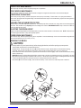
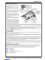
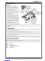
REMOVING THE BRUSH
CAUTION!
Turn the key switch off (O) and remove the key, before changing the brushes, and before opening any access panels.
1 Turn the Master Key Switch OFF and raise the Brush Deck.
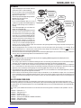
2 See figure below. Unsnap Latch (A), remove Pin (B) and Brush Access Door (C). Slide the brush out of the brush deck housing.
3 To reinstall, slide the brush under the brush deck housing, make sure the end with the large slots cut into it is inserted first.
4 Reach under the left side of the brush deck to guide the end of the brush onto the drive lug (E). Push in and turn the brush until it is firmly
seated on the drive lug.
5 IMPORTANT! Make sure that the Bearing Block (D) is seated securely in the door and orientated as shown for “old style (F)”, “new style
(G)” machines have the bearing block attached to the access door. Hold the end of the brush up while re-installing Brush Access Door (C)
to ensure that the Bearing Block on the inside of the door is securely seated in the end of the brush.
6 Re-install Pin (B) and re-secure Latch (A). Latch should secure easily. If it has to be forced, recheck the position of the brush.

A- 12 - FORM NO. 56041544 - AquaMAX™ / AX 650
A-12 / ENGLISH
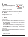
CHARGING THE BATTERIES
Charge the batteries when the Battery Fuel Gauge (3) shows a double flashing
light.
WARNING!
Use extreme caution when working with batteries. Sulfuric acid in batteries
can cause severe injury if allowed to contact the skin or eyes. Explosive
hydrogen gas is vented from the batteries through openings in the battery
caps. This gas can be ignited by any electrical arc, spark or flame.
When Servicing Batteries...
* Remove all jewelry
* Do not smoke
* Wear safety glasses, rubber gloves and a rubber apron
* Work in a well-ventilated area
* Do not allow tools to touch more than one battery terminal at a time
Check the fluid level in each battery cell before charging. Add distilled water only until the water level is 1/4” above the plates. Push the con-
nector from the charger into the Battery Charger Connector (16) on the machine. Follow the instructions on the battery charger.
CAUTION!
To avoid damage to floor surfaces, wipe water and acid from the top of the batteries after charging.
CHECKING THE BATTERY WATER LEVEL
Check the water level of the batteries at least once a week.
After charging the batteries, remove the vent caps and check the water level in each battery cell. Use distilled or demineralized water in a bat-
tery filling dispenser (available at most auto parts stores) to fill each cell to the level indicator (or to 10 mm over the top of the separators). DO
NOT over-fill the batteries!
CAUTION!
Acid can spill onto the floor if the batteries are overfilled.
Tighten the vent caps. Wash the tops of the batteries with a solution of baking soda and water (2 tablespoons of baking soda to 1 liter of
water).
BATTERY MAINTENANCE
Proper maintenance of electric vehicle batteries can greatly extend their life. Well-maintained batteries may last up to 3 years, but failure after
1 year is common if maintenance has been poor.
There are 3 simple rules for good battery maintenance:
• Maintain Proper Electrolyte Level (Weekly) - Use distilled water in batteries whenever possible. If batteries are discharged, add just
enough water to cover the plates in each cell. If batteries are fully charged, fill each cell to the bottom of the filler tube. Do not over-fill
the batteries! Do not add acid to batteries!
• Keep the Batteries Charged (Weekly) - Batteries should be charged each time that a machine is used for more than 1 hour. Machine
operators should open the battery compartment cover for charging, to avoid a concentrated build-up of hydrogen gas. Even when a ma-
chine is stored, the batteries should be charged once a month to prevent the batteries from „sulfating“. Almost all battery caps are vented,
so there‘s no need to loosen or remove them for charging.
• Keep the Batteries Clean (Monthly) - Use a damp cloth to wipe dirt from the top of the batteries. Battery terminals must be clean and
tight. If the tops of the batteries are wet after charging, the batteries have probably been over-filled or over-charged. Note: If there is
acid on the batteries, wash the tops of the batteries with a solution of baking soda and water (2) tablespoons of baking soda to 1 quart of
water.
BATTERY TESTING
A battery problem is usually recognized by the machine operator, as a decrease in the machine’s running time. This condition is usually caused
by one (or more) “dead cell” in the battery system- that is, one (or more) cell that is putting out less voltage than the other cells.
Note: Always charge batteries before testing.
There are 2 ways to find a dead cell:
• Use a hydrometer to check the specific gravity (or “state of charge”) of the fluid in each cell. A dead cell is one that reads 50 points (or
more) lower than the other cells.
• Use a volt meter to check the voltage of each battery with the brush motor running. The battery with the dead cell will read 1 or 2 volts
lower than the other batteries in the system.
If the batteries in the machine are more than 1 year old, it‘s usually best to replace the whole set, rather than replacing just one battery.

FORM NO. 56041544 - AquaMAX™ / AX 650 - A-13
ENGLISH / A-13
6 AMP CONTROL CIRCUIT CIRCUIT BREAKER
When the Control Circuit Circuit Breaker (15) trips, push the button to reset the circuit breaker.
If the circuit breaker trips repeatedly, call your local Nilfisk-Advance Distributor for service.
20 AMP WHEEL DRIVE CIRCUIT BREAKER
When the Wheel Drive Circuit Breaker (15) trips, check to see if there is debris wrapped around the wheel axle. Remove the debris from the
axle. Have the wheel drive motor checked for worn out brushes; repair or replace the motor if necessary. Push the button to reset the circuit
breaker.
If the circuit breaker trips repeatedly, call your local Nilfisk-Advance Distributor for service.
20 AMP BRUSH DRIVE CIRCUIT BREAKER
When the Brush Drive Circuit Breaker (15) trips, check to see if the brush height is set too low or if there is debris wrapped around the brush.
Adjust the brush height or remove the debris from the brush. Push the button to reset the circuit breaker.
If the circuit breaker trips repeatedly, call your local Nilfisk-Advance Distributor for service.
40 AMP VACUUM MOTOR CIRCUIT BREAKER
When the Vacuum Motor Circuit Breaker (15) trips, check the Vac Motor Filters (32) and clean or replace if necessary. Have the vacuum mo-
tors checked for worn out bearings and/or brushes or bearing failure. Repair or replace the motors if necessary. Push the button to reset the
circuit breaker.
If the circuit breaker trips repeatedly, call your local Nilfisk-Advance Distributor for service.
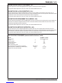
TECHNICAL SPECIFICATIONS (as installed and tested on the unit)
Model AquaMAX™ / AX 650
Model No. 56212000 / 56212260
Voltage, batteries V 36V
Battery capacity Ah 238
Protection grade IPX3
Sound power level as per ISO 3744 (at operator) dB(A)/20µPa 76
Gross weight (with acc. and batteries, full tank) lbs / kg 1,171 / 531
Vibrations at the Hand Controls m/s2<2,5m/s2

B-2 - FORM NO. 56041544 - AquaMAX™ / AX 650
B-2 / DEUTSCH
INHALTSÜBERSICHT
Seite
Einleitung ....................................................................................................................................................................... B-3
Bauteile und Service ...................................................................................................................................................... B-3
Typenschild .................................................................................................................................................................... B-3
Auspacken der Maschine .............................................................................................................................................. B-3
Wichtige Sicherheitshinweise ........................................................................................................................................ B-4
Machen Sie sich mit Ihrer Maschine vertraut. ............................................................................................................ B-5-6
Komponenten und ihre Funktion .................................................................................................................................. B-7
Vorbereitung der Maschine für den Einsatz
Einbau der Batterien ...................................................................................................................................................... B-8
Füllen des Reinigungslösungstanks .............................................................................................................................. B-8
Besprühen des Teppichs vor der Reinigung ................................................................................................................. B-8
Planung des Reinigungsvorgangs ................................................................................................................................. B-8
Bedienung der Maschine ............................................................................................................................................... B-9
Benutzung von Zubehörteilen ....................................................................................................................................... B-9
Nach dem Einsatz der Maschine ................................................................................................................................. B-10
Wartungsplan .............................................................................................................................................................. B-10
Wartung
Wartung des Saugtrichters ...........................................................................................................................................B-11
Wartung der Sprühdüse ..............................................................................................................................................B-11
Schmieren der Maschine ..............................................................................................................................................B-11
Reinigung der Saugmotorfilter ......................................................................................................................................B-11
Einstellen der Bürstenhöhe ..........................................................................................................................................B-11
Wartung der Power-Bürste ...........................................................................................................................................B-11
Ausbau der Bürste ........................................................................................................................................................B-11
Laden der Batterien ..................................................................................................................................................... B-12
Fehlerbehebung
Automatsicherung - Steuerung .................................................................................................................................... B-13
Automatsicherung - Radantrieb ................................................................................................................................... B-13
Automatsicherung - Bürstenantrieb ............................................................................................................................. B-13
Automatsicherung - Saugmotor ................................................................................................................................... B-13
Technische Daten ........................................................................................................................................................ B-13

FORM NO. 56041544 - AquaMAX™ / AX 650 - B-3
DEUTSCH / B-3
EINLEITUNG
Diese Betriebsanleitung soll Ihnen helfen, Ihren Nilfisk-Advance AquaMAX™ / AX 650 optimal einzusetzen. Lesen Sie die
Betriebsanleitung vor Inbetriebnahme der Maschine sorgfältig durch.
Hinweis: Fett gedruckte Zahlen in Klammern weisen auf ein auf den Seiten B-5 – B-6 abgebildetes Teil hin.
Dieses Produkt ist ausschließlich für den gewerblichen Einsatz bestimmt.
BAUTEILE UND SERVICE
Eventuell erforderliche Reparaturen sollten von Ihrem autorisierten Nilfisk-Advance-Servicezentrum vorgenommen werden. Dort stehen im
Werk ausgebildete Fachkräfte und Nilfisk-Advance-Originalteile zur Verfügung.
Wenden Sie sich wegen Ersatzteilen bzw. Servicearbeiten an den unten angeführten NILFISK-ADVANCE HÄNDLER. Geben Sie dabei das
Modell und die Seriennummer Ihrer Maschine an.
(Händler: Bitte hier Aufkleber anbringen.)
TYPENSCHILD
Die Modellnummer und die Seriennummer Ihrer Maschine sind dem Typenschild an der Maschine zu entnehmen. Diese Angaben sind
bei der Bestellung von Ersatzteilen für die Maschine erforderlich. Tragen Sie nachfolgend die Modellnummer und die Seriennummer Ihrer
Maschine ein, um später darauf Bezug nehmen zu können.
MODELLNUMMER
SERIENNUMMER
AUSPACKEN DER MASCHINE
Prüfen Sie den Verpackungskarton und die Maschine sofort nach Anlieferung sorgfältig auf Schäden. Heben Sie bei einem Schaden den
Versandkarton auf, damit dieser überprüft werden kann. Setzen Sie sich unverzüglich mit der Nilfisk-Advance-Kundendienstabteilung in
Verbindung, um den Transportschaden zu melden.

B-4 - FORM NO. 56041544 - AquaMAX™ / AX 650
B-4 / DEUTSCH
WICHTIGE SICHERHEITSHINWEISE
Diese Maschine ist lediglich für gewerbliche Anwendung geeignet, z. B. in Hotelbetrieben, Schulen, Krankenhäusern, Fabriken,
Geschäften und Büroräumen. Die Maschine ist nicht für den normalen Haushalt geeignet.
Bei der Benutzung eines Elektrogerätes sind die grundlegenden Vorsichtsmaßnahmen zu beachten. Dazu gehören unter
anderem die im Folgenden erwähnten Maßnahmen:
Lesen Sie alle Anweisungen vor Inbetriebnahme der Maschine sorgfältig durch.
VORSICHT!
Verminderung der Brand- und Verletzungsgefahr sowie der Gefahr durch Stromschlag:
* Diese Maschine darf nur von qualifizierten und hierzu berechtigten Personen bedient werden.
* Halten Sie Funken, offenes Feuer und Rauch entwickelnde Stoffe von den Batterien fern. Während des Normalbetriebs werden
explosive Gase freigesetzt
* Beim Laden der Batterien entsteht hochexplosiver gasförmiger Wasserstoff. Laden Sie die Batterien nur in gut belüfteten
Bereichen, weit entfernt von offenem Feuer. Beim Aufladen der Batterien ist das Rauchen verboten.
* Tagen Sie keinen Schmuck, wenn Sie in der Nähe von elektrischen Komponenten arbeiten.
* Schalten Sie den Schlüsselschalter aus (stellen Sie ihn auf O), und klemmen Sie die Batterien ab, bevor Sie an den elektrischen
Komponenten Wartungsarbeiten ausführen.
* Arbeiten Sie niemals unter einer Maschine, ohne diese mit Sicherheitskeilen oder Stützböcken zu sichern.
* Verwenden Sie keine entflammbaren Reinigungslösungen, nehmen Sie die Maschine nicht über oder in der Nähe solcher
Stoffe in Betrieb, und benutzen Sie die Maschine nicht in Bereichen, in denen brennbare Flüssigkeiten gelagert werden.
* Reinigen Sie diese Maschine nicht mit einem Druckreiniger.
* Diese Maschine darf auf Rampen und Steigungen mit einer Steigung von mehr als 2 Prozent nicht gefahren werden.
* Benutzen Sie die Bürsten nur mit dem mitgelieferten Zubehör oder wie im Handbuch beschrieben ist. Die Verwendung anderer
Bürsten kann die Sicherheit beeinträchtigen.
ACHTUNG!
* Diese Maschine ist nicht zum Einsatz auf öffentlichen Wegen und Straßen zugelassen.
* Diese Maschine ist nicht zur Beseitigung gesundheitsgefährdender Stäube geeignet.
* Sorgen Sie beim Einsatz dieser Maschine dafür, dass andere Personen, insbesondere Kinder, nicht gefährdet werden.
* Lesen Sie vor Wartungsarbeiten alle diesbezüglichen Anweisungen sorgfältig durch.
* Lassen Sie die Maschine nicht unbeaufsichtigt stehen, ohne vorher den Schlüsselschalter auszuschalten (stellen Sie ihn auf
O), den Schlüssel zu entfernen und die Maschine zu sichern.
* Schalten Sie den Schlüsselschalter aus (O) und ziehen Sie den Schlüssel ab, bevor Sie die Bürsten austauschen und eine
Wartungsluke öffnen.
* Treffen Sie geeignete Maßnahmen, um zu verhindern, dass sich Ihre Haare, Schmuckgegenstände oder lose Kleidungsstücke
in beweglichen Teilen der Maschine verfangen.
* Beim Betrieb dieser Maschine bei Temperaturen unter dem Gefrierpunkt ist besondere Vorsicht geboten. Das Wasser im
Frischwassertank, im Schmutzwassertank und in den Schlauchleitungen kann gefrieren.
* Vor der Verschrottung der Maschine sind die Batterien auszubauen. Batterien müssen entsprechend den geltenden
Umweltvorschriften entsorgt werden.
* Nicht für Oberflächen mit einem Neigungsgrad geeignet, der die Markierung auf der Maschine überschreitet.
* Vor Inbetriebnahme der Maschine müssen alle Türen und Abdeckungen an die Stellen platziert werden wie im Handbuch
beschrieben.
BEWAHREN SIE DIESE ANLEITUNG AUF.

FORM NO. 56041544 - AquaMAX™ / AX 650 - B-5
DEUTSCH / B-5
MACHEN SIE SICH MIT IHRER MASCHINE VERTRAUT.
Beim Lesen dieser Betriebsanleitung werden Ihnen hin und wieder fett gedruckte Zahlen in Klammern begegnen - beispielsweise (2). Diese
Zahlen verweisen auf ein Bauteil auf dieser Seite. Schlagen Sie gegebenenfalls diese Seite auf, um sich über die Einbaulage von im Text
erwähnten Komponenten zu informieren.
1 Oberer (Schmutzwasser-) Tank
2 Abdeckhaube des Schmutzwassertanks
3 Batterie-Zustandsanzeiger
4 Hauptschlüsselschalter
5 Pumpenschalter
6 Saugschalter
7 Stundenzähler
8 Bürstenanpressdruck-Anzeige
9 Geschwindigkeitsregler
10 Bedienerhandgriff
11 Fahrschalter
12 Hebel zum Anheben des Bürstengehäuses
13 Arretierung des oberen Tanks
14 Zubehöranschluss
15 Automatsicherungen
Steuerung 6 A
Saugmotor 40 A
Bürstenmotor 20 A
Antriebsmotor 20 A
16 Batterie-Ladeanschluss
17 Ablassschlauch des Schmutzwassertanks
18 Saugtrichter
19 Einstellknopf für die Bürstenhöhe
20 Bürstengehäuse
21 Reinigungslösungs-Ablassschlauch / Füllstandsanzeiger
22 Deckel der Reinigungslösungs-Einfüllöffnung
23 Saugleitung
24 Leitung zum Schmutzwassertank
25 Düsenwahlschalter
26 Stützrolle
27 Hintere Rollen

B-6 - FORM NO. 56041544 - AquaMAX™ / AX 650
B-6 / DEUTSCH
28 Unterer (Frischwasser-) Tank - Spülanschluss
29 Bürstenwartungsklappe
30 Arretierung der Bürstenwartungsklappe
31 Bürstengehäuse-Freigabehebel
32 Saugmotorfilter
33 Automatisches Schwimmer-Absperrventil
34 Schmutzwasser-Folienbehälter
35 Abstandsrolle
36 Pumpen-Rohrfilter
37 Unterer (Frischwasser-) Tank
38 Abstandsrollen-Freigabeknopf

FORM NO. 56041544 - AquaMAX™ / AX 650 - B-7
DEUTSCH / B-7
KOMPONENTEN UND IHRE FUNKTION:
Oberer (Schmutzwasser-) Tank (1): Schmutzwasser vom Teppich wird hier in einem Folienbehälter aufgefangen (34). Der Bereich außerhalb des Schmutzwasser-Folienbehälters (34)
wird für zusätzliche saubere Reinigungslösung verwendet. Die Batterien und Saugmotorfilter (32) sind zugänglich, wenn dieser Tank seitlich aufgeklappt wird.
Abdeckhaube des Schmutzwassertanks (2): An dieser Stelle gelangt das Schmutzwasser in den Folienbehälter. Außerdem befindet sich hier ein automatisches Schwimmer-Absperrventil
(33), welches die Saugöffnung zu den Saugmotoren schließt, wenn der Folienbehälter voll ist. Entfernen Sie diese Abdeckung, um den Schmutzwasser-Folienbehälter auszuspülen oder
den Reinigungslösungstank zu füllen.
Batterie-Zustandsanzeige (3): Zeigt den augenblicklichen Ladezustand der Batterien an. Ein doppelter blinkender Balken weist auf niedrigen Ladezustand der Batterien hin, dann müssen
Sie sofort aufladen. HINWEIS: Wenn die Batterieanzeige blinkt, werden alle Systeme außer dem Radantrieb abgeschaltet.
Hauptschlüsselschalter (4): Der Haupt-Stromschalter.
Pumpenschalter (5): Mit dieser Taste wird die Betriebsart des Frischwasser-/Reinigungslösungssystems gewählt. Das System verfügt über 3 Betriebsarten. Die Betriebsarten sind: AUTO
/ AUS / EIN. Im Folgenden finden Sie eine Beschreibung der drei Betriebsarten.
BETRIEBSART AUTO: In dieser Betriebsart wird die Reinigungslösungszufuhr immer dann EINGESCHALTET, wenn die Bürste abgesenkt wird und die Maschine sich vorwärts bewegt.
Die Reinigungslösungszufuhr wird ausgeschaltet, wenn die Maschine sich nicht bewegt, rückwärts bewegt wird oder die Bürste angehoben ist.
BETRIEBSART AUS: In dieser Betriebsart ist die Reinigungslösungszufuhr ausgeschaltet.
BETRIEBSART EIN: Diese Betriebsart ist für den Betrieb mit Zubehörteilen vorgesehen. Die Pumpe ist immer EINGESCHALTET, solange der Hauptschlüsselschalter (4) auf EIN steht.
Saug-Knopf (6): Mit diesem Knopf wird die Betriebsart des Saugsystems gewählt. Das System verfügt über 3 Betriebsarten. Die Betriebsarten sind: AUTO / AUS / EIN. Im Folgenden
finden Sie eine Beschreibung der drei Betriebsarten.
BETRIEBSART AUTO: In dieser Betriebsart wird die Reinigungslösungszufuhr EINGESCHALTET, sobald die Bürste abgesenkt wird und der Hauptschlüsselschalter (4) auf EIN steht. In
dieser Betriebsart bleibt die Saugleistung 10 Sekunden lang eingeschaltet, nachdem die Bürste angehoben wurde.
BETRIEBSART AUS: In dieser Betriebsart ist das Saugsystem ausgeschaltet.
BETRIEBSART EIN: Diese Betriebsart ist für den Betrieb mit Zubehörteilen vorgesehen. Das Saugsystem ist immer EINGESCHALTET, solange der Hauptschlüsselschalter (4) auf EIN
steht.
Stundenzähler (7): Zeigt die Anzahl der Betriebsstunden der Maschine an. HINWEIS: Der Stundenzähler läuft nur, wenn die Saugmotoren laufen.
Bürstenanpressdruck-Anzeige (8): Die Anzeige sollte 8-15 A (grüner Bereich) anzeigen. Liegt die Anzeige außerhalb dieses Bereichs, muss die Bürstenhöhe nachgestellt werden.
Geschwindigkeitsregler (9): Drehen Sie diesen Knopf im Uhrzeigersinn, um die maximale Drehzahl zu erhöhen, und gegen den Uhrzeigersinn, um die maximale Drehzahl zu verringern.
Bedienerhandgriff (10): Mit diesem Handgriff steuert der Bediener die Maschine.
Fahrschalter (11): Zum Vorwärtsfahren der Maschine muss der Bediener den Fahrschalter vordrücken, zum Rückwärtsfahren zurückziehen. Die Fahrgeschwindigkeit lässt sich regeln,
wenn der Fahrschalter mehr oder weniger weit in Vorwärts- bzw. Rückwärtsrichtung geschoben bzw. gezogen wird. Wenn sich das Bürstengehäuse in abgesenkter Position (DOWN)
befindet, sind Bürste und Pumpe in Betrieb, wenn der Fahrschalter in einer der beiden Richtungen aktiviert ist. Beide werden jedoch angehalten, wenn der Fahrschalter länger als eine
Sekunde losgelassen wird. HINWEIS: Die Pumpe läuft nicht, wenn der Fahrschalter in Rückwärtsstellung steht.
Hebel zum Anheben des Bürstengehäuses (12): Mit diesem Hebel wird das Bürstengehäuse angehoben oder abgesenkt.
Sobald das Bürstengehäuse abgesenkt wird, werden die Pumpe und die Saugtrichter EINGESCHALTET. Wenn die entsprechenden Hebel sich in der Position AUTO befinden, werden sie
AUSGESCHALTET. HINWEIS: Zum Betrieb der Pumpe muss sich die Maschine vorwärts bewegen, zum Einschalten der Bürste vorwärts oder rückwärts. Das Saugsystem schaltet sich 10
Sekunden nach Anheben des Bürstengehäuses ab.
Arretierung des oberen Tanks (13): Diese Arretierung sichert den oberen Tank (1) an der Maschine, damit sich beim Betrieb der Tank nicht öffnet, da der Bedienerhandgriff (10) am
oberen Tank montiert ist.
Zubehöranschluss (14): Hier wird externes Zubehör angeschlossen.
Automatsicherungen (15)
6 A - Steuerung - Überlastschutz: Wird sie ausgelöst, springt der Sicherungsknopf heraus. Warten Sie bis zum Einschalten der Sicherung eine Minute und drücken Sie dann den Knopf.
Sollte eine Sicherung mehrmals ausgelöst werden, wenden Sie sich an den Kundendienst.
40 A – Saugmotoren: Schützt die Saugmotoren der Maschine vor Überlastung. Wird sie ausgelöst, springt der Sicherungsknopf heraus. Warten Sie bis zum Einschalten der Sicherung
eine Minute und drücken Sie dann den Knopf. Sollte eine Sicherung mehrmals ausgelöst werden, wenden Sie sich an den Kundendienst.
20A – Bürstenmotor: Schützt den Bürstenmotor der Maschine vor Überlastung. Wird sie ausgelöst, springt der Sicherungsknopf heraus. Warten Sie bis zum Einschalten der Sicherung
eine Minute und drücken Sie dann den Knopf. Sollte eine Sicherung mehrmals ausgelöst werden, wenden Sie sich an den Kundendienst.
20 A – Antriebsmotor: Schützt den Antriebsmotor vor Überlastung. Wird sie ausgelöst, springt der Sicherungsknopf heraus. Warten Sie bis zum Einschalten der Sicherung eine Minute
und drücken Sie dann den Knopf. Sollte eine Sicherung mehrmals ausgelöst werden, wenden Sie sich an den Kundendienst.
Batterie-Ladeanschluss (16): Verbinden Sie das Batterieladegerät mit diesem Anschluss, um die Batterien zu laden.
Ablassschlauch des Schmutzwassertanks (17): Zum Entleeren des Schmutzwassertanks. HINWEIS: Halten Sie das Leitungsende über den Wasserspiegel im Tank, um plötzliches
unkontrolliertes Auslaufen von Schmutzwasser beim Entfernen des Verschlusses zu verhindern.
Saugtrichter (18): Entfernt nach dem Bürsten die überschüssige Reinigungslösung.
Einstellschraube für die Bürstenhöhe(19): Zur Höheneinstellung des Bürstengehäuses. Drehen Sie die Schraube im Uhrzeigersinn, um das Bürstengehäuse anzuheben und entgegen
dem Uhrzeigersinn, um das Bürstengehäuse abzusenken.
HINWEIS: Verwenden Sie die Einstellschraube in Verbindung mit der Bürstenanpressdruck-Anzeige (8).
Bürstengehäuse (20): Enthält den Bürstenantriebsmotor und die Bürste.
Reinigungslösungs-Ablassschlauch / Füllstandanzeige (21): Zum Entleeren des Frischwassertanks bzw. zur Anzeige des Füllstands. Die Skala befindet sich seitlich an der Maschine
neben der Leitung.
Deckel für Reinigungslösungs-Einfüllanschluss (22): Der Frischwassertank kann entweder hier oder durch die vordere Öffnung auf dem Schmutzwassertank gefüllt werden, wenn die
Abdeckhaube des Schmutzwassertanks entfernt wird.
Saugleitung (23): Diese Leitung ist am Saugmotor angeschlossen, um ein Vakuum im Schmutzwasser-Folienbehälter zu erzeugen.
Schmutzwasserleitung (24): Diese Leitung verbindet den Saugtrichter mit (18) der Abdeckhaube des Schmutzwassertanks (2), und leitet Schmutzwasser in den Folienbehälter.
Düsenwahlschalter (25): Mit diesem Schalter wählen Sie die Reinigungsarten Schnellreinigung oder Tiefenreinigung. HINWEIS: Der Geschwindigkeitsregler (9) hat zwei entsprechende
Einstellungen.
Schnellreinigungsmodus: Weniger Reinigungslösung, höhere Arbeitsgeschwindigkeit. Empfohlen für häufige Oberflächenreinigung.
Tiefenreinigungsmodus: Mehr Reinigungslösung, langsamere Arbeitsgeschwindigkeit. Empfohlen für eine weniger häufige Tiefenreinigung.
Stützrolle (26): Diese Rolle stabilisiert die Maschine, wenn der obere (Schmutzwasser-) Tank geöffnet wird (1).
Hintere Rollen (27): Diese beiden Rollen und das Hauptantriebsrad tragen das Gewicht der Maschine und gestatten ein einfaches Manövrieren um Kurven.
Unterer (Frischwasser-) Tank - Verschlusskappe der Ausspülöffnung (28): Ermöglicht den Zugang zum unteren (Frischwasser-)Tank zum Ausspülen mit klarem Wasser.
Bürstenwartungsklappe (29): Durch diese Öffnung kann die Power-Bürste aus- oder eingebaut werden.
Arretierung der Bürstenwartungsklappe (30): Lösen Sie diese Arretierung, um Zugang zur Power-Bürste zu erlangen.
Bürstengehäuse-Freigabeknopf (31): Ziehen Sie diesen Knopf heraus und schieben Sie das Bürstengehäuse nach rechts, bis es einrastet. So können Sie unter Regalen, Geländern etc.
putzen.
Saugmotorfilter (32): Ansaugfilter für den Saugmotor. Beachten Sie die im Serviceplan angegebenen Wartungsintervalle.
Automatisches Schwimmer-Absperrventil (33): Das automatische Schwimmer-Absperrventil schließt die Saugöffnung, wenn der Schmutzwasser-Folienbehälter (34) voll ist.
An der plötzlichen Änderung des Geräuschs der Saugmotoren erkennen Sie, wann das Schwimmerventil schliesst. Wenn sich das Schwimmerventil schliesst, muss der
Schmutzwassertank entleert werden. Bei geschlossenem Schwimmerventil kann die Maschine kein Schmutzwasser aufnehmen.
Schmutzwasser-Folienbehälter (34): Enthält das vom Teppich aufgenommene Schmutzwasser. Das Fassungsvermögen beträgt insgesamt 113,5 Liter.
Abstandsrolle (35): Ein ausfahrbarer Stoßfänger mit 3 Positionen, mit dessen Hilfe die Maschine leichter an Wänden entlang geführt werden kann.
Pumpenrohrleitungsfilter (36): Dieser Filter entfernt Verunreinigungen aus der Reinigungslösung, bevor diese die Pumpe durchfliesst. Lassen Sie die Lösung vor der Reinigung des
Filters ab.
Unterer (Frischwasser-) Tank (37): Dieser Tank kann zusammen mit dem oberen Tank insgesamt 151 Liter (40 Gallonen) Lösung aufnehmen.
Abstandsrollen-Freigabeknopf (38): Mit diesem Knopf schieben Sie die Abstandsrolle hinein oder heraus, um den Abstand der Maschine von der Wand zu ändern.

B-8 - FORM NO. 56041544 - AquaMAX™ / AX 650
B-8 / DEUTSCH
EINBAU DER BATTERIEN
WARNUNG!
Bei der Arbeit an Batterien ist äußerste Vorsicht geboten. Die Schwefelsäure
in den Batterien kann bei Berührung der Haut oder der Augen erhebliche
Verletzungen verursachen. Durch die Öffnungen in den Batteriezellenkappen
entweicht explosiver, gasförmiger Wasserstoff aus dem Inneren der
Batterien. Dieses Gas kann sich durch einen elektrischen Lichtbogen, einen
Funken oder eine offene Flamme entzünden.
Treffen Sie vor bzw. bei der Arbeit an den Batterien folgende
Sicherheitsvorkehrungen:
* Legen Sie jeglichen Schmuck ab.
* Rauchen Sie nicht.
* Setzen Sie eine Schutzbrille auf und legen Sie Gummihandschuhe und
eine Gummischürze an.
* Sorgen Sie für eine gute Belüftung des Arbeitsbereiches.
* Achten Sie darauf, dass Werkzeuge nie mehr als eine Batterieklemme
gleichzeitig berühren.
ACHTUNG!
An den elektrischen Komponenten dieser Maschine können erhebliche
Schäden entstehen, wenn die Batterien nicht ordnungsgemäß eingebaut
und angeschlossen werden. Der Einbau der Batterien sollte einem
Nilfisk-Advance-Mitarbeiter, einem qualifizierten Elektriker oder der
Batterieherstellerfirma überlassen werden.
1 Untersuchen Sie die Batterien nach dem Auspacken aus der Versandkiste
sorgfältig auf Risse oder sonstige Beschädigungen. Sollte ein Schaden
vorliegen, setzen Sie sich zur Anmeldung eines Schadensanspruches entweder
mit dem Transportunternehmen, das die Batterien angeliefert hat, oder mit dem
Batteriehersteller in Verbindung.
2 Schalten Sie den Hauptschlüsselschalter (4) auf (4) AUS (OFF), und ziehen Sie
den Schlüssel ab.
3 Öffnen Sie den oberen (Schmutzwasser-) Tank (1). Nehmen Sie die Batteriekabel
aus Batteriefach heraus.
4 Die Maschine wird ab Werk mit Batteriekabeln zum Einbau von vier Batterien 6 Volt,
244 Ah geliefert. Heben Sie die Batterien vorsichtig in das Batteriefach, und stellen
Sie sie genau nach dem abgebildeten Muster auf. Schieben Sie die Batterien so
nahe wie möglich zur Rückseite der Maschine.
5 Minuspol und Pluspol sind an den Batteriekabeln mit „+“ bzw. „–“ gekennzeichnet.
Schließen Sie die Batteriekabel wie abgebildet an; die mit „+“ gekennzeichneten
Kabelklemmen müssen an den Pluspolen der Batterien, die mit „–“ markierten
Kabelklemmen an den Minuspolen der Batterien angeschlossen werden. Verlegen
Sie die Batteriekabel so, dass die Batterieentlüftungskappen bei der Wartung der
Batterien leicht zu entfernen sind.
6 Ziehen Sie die Muttern an den Batteriepolen vorsichtig fest, sodass sich die
Klemmen nicht mehr auf dem Batteriepolen drehen lassen. Ziehen Sie die Muttern
dann jeweils noch eine weitere Umdrehung fest. Die Klemmen dürfen nicht zu fest
angezogen werden, da sie anderenfalls bei späteren Wartungsarbeiten nur sehr
schwer wieder zu entfernen sind.
7 Sprühen Sie auf die Klemmen und Batteriepole ein geeignetes Pflegemittel auf (in
KFZ-Zubehörgeschäften erhältlich).
8 Setzen Sie auf jede der Klemmen eine schwarze Gummikappe auf.
FÜLLEN DES REINIGUNGSLÖSUNGSTANKS
1 Nehmen Sie entweder den Deckel der Reinigungslösungs-Einfüllöffnung (22) oder
die Abdeckhaube des Schmutzwassertanks (2) ab. HINWEIS: Achten Sie beim
Füllen des Reinigungslösungstanks von der Oberseite des oberen Tanks (1) aus
darauf, dass Sie die Lösung in die Öffnung direkt an der Vorderseite der Maschine
gießen.
2 Richten Sie sich nach der Verdünnungsvorschrift des Herstellers auf dem Behälter
der Reinigungslösung. Errechnen Sie die passende Menge des beizufügenden
Reinigungsmittels für einen Tank mit einem Fassungsvermögen von 151 Litern
(40 US-Gallonen). Beste Ergebnisse erhalten Sie mit dem speziellen chemischen
Absaugreiniger Nilfisk-Advance CarpeTeam™, der für Teppichabsauggeräte von
Nilfisk-Advance entwickelt wurde.
3 Gießen Sie die Chemikalie in den Frischwassertank und füllen Sie den Tank
mit warmem Wasser. HINWEIS: Kontrollieren Sie beim Füllen des Tanks den
Füllstandsanzeiger (21) der Lösung. Füllen Sie Flüssigkeit auf, bis die Markierung
für 40 Gallonen erreicht ist.
4 Schließen Sie wieder den Deckel der Reinigungslösungs-Einfüllöffnung (22) bzw.
die Abdeckhaube des Schmutzwassertanks (2) an der Maschine. HINWEIS:
Kontrollieren Sie, ob die Abdeckhaube richtig auf dem Tank sitzt.
ACHTUNG!
Es dürfen nur nicht-brennbare, schaumfreie
Flüssigreinigungsmittel verwendet werden, die ausdrücklich für
Teppichreinigungsmaschinen zugelassen sind.
VORBEREITUNGEN VOR VERWENDUNG DER
AQUAMAX™ / AX 650
Saugen Sie den Teppich gründlich ab, bevor Sie die automatische Reinigung
mit AquaMAX™ / AX 650 beginnen.
BESPRÜHEN DES TEPPICHS VOR DER
REINIGUNG
Sprühen Sie Flecken und stark begangene Bereiche vor dem Absaugen
ein. Benutzen Sie dazu ein Handsprühgerät oder einen Drucksprüher
von “Hudson”. Mischen Sie die Lösung zum vorherigen Einsprühen
entsprechend den Anweisungen des Herstellers der chemikalischen
Reinigungsmittels.
PLANUNG DES REINIGUNGSVORGANGS
Kontrollieren und planen Sie Ihre Arbeit, bevor Sie mit dem Absaugen
beginnen. Teilen Sie den Raum in Abschnitte ein. Sorgen Sie für eine
Überlappung der Bahnen von etwa 25-75 mm (2-5 Zoll).
La page est en cours de chargement...
La page est en cours de chargement...
La page est en cours de chargement...
La page est en cours de chargement...
La page est en cours de chargement...
La page est en cours de chargement...
La page est en cours de chargement...
La page est en cours de chargement...
La page est en cours de chargement...
La page est en cours de chargement...
La page est en cours de chargement...
La page est en cours de chargement...
La page est en cours de chargement...
La page est en cours de chargement...
La page est en cours de chargement...
La page est en cours de chargement...
La page est en cours de chargement...
La page est en cours de chargement...
La page est en cours de chargement...
La page est en cours de chargement...
La page est en cours de chargement...
La page est en cours de chargement...
La page est en cours de chargement...
La page est en cours de chargement...
La page est en cours de chargement...
La page est en cours de chargement...
La page est en cours de chargement...
La page est en cours de chargement...
La page est en cours de chargement...
La page est en cours de chargement...
La page est en cours de chargement...
La page est en cours de chargement...
-
 1
1
-
 2
2
-
 3
3
-
 4
4
-
 5
5
-
 6
6
-
 7
7
-
 8
8
-
 9
9
-
 10
10
-
 11
11
-
 12
12
-
 13
13
-
 14
14
-
 15
15
-
 16
16
-
 17
17
-
 18
18
-
 19
19
-
 20
20
-
 21
21
-
 22
22
-
 23
23
-
 24
24
-
 25
25
-
 26
26
-
 27
27
-
 28
28
-
 29
29
-
 30
30
-
 31
31
-
 32
32
-
 33
33
-
 34
34
-
 35
35
-
 36
36
-
 37
37
-
 38
38
-
 39
39
-
 40
40
-
 41
41
-
 42
42
-
 43
43
-
 44
44
-
 45
45
-
 46
46
-
 47
47
-
 48
48
-
 49
49
-
 50
50
-
 51
51
-
 52
52


Nilfisk-Advance 56212000 Instructions For Use Manual
- Catégorie
- Machine à plancher
- Taper
- Instructions For Use Manual
- Ce manuel convient également à
dans d''autres langues
- English: Nilfisk-Advance 56212000
- Deutsch: Nilfisk-Advance 56212000
Documents connexes
Autres documents
-
Minuteman Ambassador 20 C8420-240 Manuel utilisateur
-
Nilfisk-Advance America BRX 700 Series Manuel utilisateur
-
Windsor Chariot 3 iExtract 26 DUO Le manuel du propriétaire
-
-
Alto SCRUBTEC R 366 Manuel utilisateur
-
Kärcher Armada® BRC 40/22 C Le manuel du propriétaire
-
Nilfisk 551 D Le manuel du propriétaire