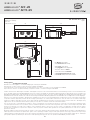
S+S Regeltechnik HYDRASGARD AFTF-20-I VA Operating Instructions, Mounting & Installation
- Taper
- Operating Instructions, Mounting & Installation

HYGRASGARD
®
AFF - xx
HYGRASGARD
®
AFTF - xx
D G F r
Herzlichen Glückwunsch!
Sie haben ein deutsches Qualitätsprodukt erworben.
Congratulations!
You have bought a German quality product.
Félicitations !
Vous avez fait l’acquisition d’un produit allemand de qualité.
Примите наши поздравления !
Вы приобрели качественный продукт, изготовленный в Германии.
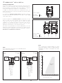
D
Bedienungs- und Montageanleitung
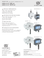
Aufputz- Feuchte- und Temperaturfühler
(± 1,8 % ⁄ ± 2,0), kalibrierfähig,
mit Mehrbereichsumschaltung
und aktivem ⁄ passivem Ausgang
G
Operating Instructions, Mounting & Installation
On-wall humidity and temperature sensors
(± 1.8 % ⁄ ± 2,0), calibratable,
with multi-range switching
and active ⁄ passive output
F
Notice d’instruction
Sonde d’humidité et de température
(± 1,8 % ⁄ ± 2,0), pour montage en saillie,
étalonnable, avec commutation multi-gamme
et sortie active ⁄ passive
r
Руководство по монтажу и обслуживанию
Датчик влажности и температуры
для открытой установки (± 1,8 % ⁄ ± 2,0), калибруемый,
с переключением между несколькими диапазонами
и активным ⁄ пассивным выходом
AFF ⁄ AFTF
(± 2,0)
AFTF - 20
(± 1,8 %)
AFF - SD ⁄ AFTF - SD
(± 2,0)
AFF - 25 ⁄ AFTF - 25
(± 1,8 %)
S+S REGELTECHNIK GMBH
PIRNAER STRASSE 20
90411 NÜRNBERG ⁄ GERMANY
FON +49 (0) 911 ⁄ 5 19 47- 0
FAX +49 (0) 911 ⁄ 5 19 47- 70
www.SplusS.de
6000-3200-0000-1XX 32000-2019 V103 02 ⁄ 2019

2
D G F r
HYGRASGARD
®
AFF, AFF - 20
HYGRASGARD
®
AFTF, AFTF - 20
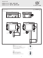
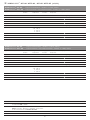
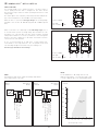
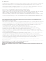
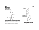
Maßzeichnung
Dimensional drawing
Plan coté
Габаритный чертеж
AFF ⁄ AFTF
(± 2,0)
AFF - 20 ⁄ AFTF - 20
(± 1,8 %)
(Tyr2 )
~ 35
50
126
90
112
20
4
M16x1.5
ø16
~ 137
~ 35
112
20
4
M16x1.5
ø16
~ 211
SF -K
Kunststoff
-Sinterfilter (Standard)
Plastic
sinter filter (standard)
Filtre fritté en matière
synthétique
(standard)
Сменный
пластиковый
спеченный фильтр
(стандартное исполнение)
SF -M
Metall
-Sinterfilter (optional)
Metal
sinter filter (optional)
Filtre fritté en
métal
(en option)
Металлокерамический
фильтр (опция)

3
D
HYGRASGARD
®
AFF - xx ⁄ AFTF - xx
Rev. 2019 - V25
SD =
Rev. 2019 - V23
Kalibrierfähiger Außen-Feuchte-
⁄
Temperatursensor
HYGRASGARD
®
AFF ⁄ AFTF
(± 2,0 %)
AFF - SD ⁄ AFTF - SD
(± 2,0 % ) und
AFF - 20 ⁄ AF TF - 20
(± 1,8 %) mit
Kunststoff -Sinterfilter (optional Metall -Sinterfilter) oder
AFF - 25 ⁄ AFTF - 25
(± 1,8 %)
mit steckbarem Metall -Sinterfilter;
Klemmkasten gehäuse aus schlagzähem Kunststoff,
wahl weise mit ⁄ ohne Display
.
Er misst die relative Feuchte und ⁄ oder die Temperatur der Luft und wandelt die Messgröße in ein Normsignal von 0 - 10 V oder 4...20 mA um. Er
verfügt über vier umschaltbare Temperatur bereiche und findet Anwendung in nicht aggressiver, staubfreier Umgebung, in der Kälte-, Klima- Lüftungs-
und Reinraum technik. Die relative Feuchte (in % r.H.) ist der Quotient aus dem Wasserdampfpartialdruck und dem Sättigungs dampfdruck bei der
jeweiligen Gastemperatur. Die Messumformer sind für die exakte Erfassung der Feuchte bestimmt. Es wird ein digitaler, langzeitstabiler Sensor als
Mess element für die Feuchtemessung verwendet. Ein Feinabgleich durch den Anwender ist möglich.
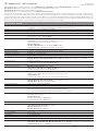
TECHNISCHE DATEN
Spannungsversorgung: 24 V AC (± 20 %) und 15...36 V DC bei U -Variante
15...36 V DC bei I -Variante, bürdenabhängig, Restwelligkeit stabilisiert ± 0,3 V
Bürde: R
a
(Ohm) = (U
b
-14 V) ⁄ 0,02 A bei I -Variante
Lastwiderstand: R
L
> 5 kOhm bei U -Variante
Leistungsaufnahme: < 1,1 VA ⁄ 24 V DC ; < 2,2 VA ⁄ 24 V AC
Sensoren:
digitaler Feuchtesensor, mit integriertem Temperatursensor,
kleine Hysterese, hohe Langzeitstabilität
Sensorschutz:
AFF ⁄ AFTF, AFF - 20 ⁄ AFTF - 20, AFF - SD ⁄ AFTF - SD:
Kunststoff
-Sinterfilter, Ø 16 mm, L = 35 mm, austauschbar
(optional Metall-Sinterfilter, Ø 16 mm, L = 32 mm)
AFF - 25 ⁄ AFTF - 25:
steckbarer Messkopf
(Fühler) aus Edelstahl
V2A
(1.4301)
mit Metall-Sinterfilter, Ø 16 mm, L = 88,5 mm, austauschbar
FEUCHTE
Messbereich Feuchte: 0...100 % r. H. (Ausgang entspricht 0 -10 V oder 4...20 mA)
Arbeitsbereich Feuchte: 0...95 % r. H. (ohne Betauung)
zulässige Luftfeuchte: < 95 % r. H., nicht kondensierende Luft
Abweichung Feuchte:
AFF ⁄ AFTF, AFF - SD ⁄ AFTF - SD:
typisch
± 2,0 %
(20...80 % r. H.) bei +25 °C, sonst ± 3,0 %
AFF - 20 ⁄ AFTF - 20, AFF - 25 ⁄ AFTF - 25:
typisch
± 1,8 %
(10...90 % r. H.) bei +25 °C, sonst ± 2,0 %
Ausgang Feuchte: 0 - 10 V bei U-Variante
4...20 mA bei I-Variante, siehe Bürdendiagramm
TEMPERATUR
Messbereich Temperatur:
Mehrbereichsumschaltung
(siehe Tabelle)
–35...+35 °C; –35...+75 °C; 0...+50 °C; 0...+80 °C
(Ausgang entspricht 0 -10 V oder 4...20 mA)
Umgebungstemperatur:
AFF ⁄ AFTF, AFF - 20 ⁄ AFTF - 20, AFF - 25 ⁄ AFTF - 25:
Lagerung –35...+85 °C; Betrieb – 30...+80 °C, nicht kondensierend
AFF - SD ⁄ AFTF - SD:
Lagerung –35...+85 °C; Betrieb – 30...+70 °C, nicht kondensierend
Abweichung Temperatur:
AFF ⁄ AFTF:
typisch ± 0,4 K bei +25 °C
AFF - 20 ⁄ AFTF - 20, AFF - 25 ⁄ AFTF - 25:
typisch ± 0,2 K bei +25 °C
AFF - SD ⁄ AFTF - SD:
typisch ± 0,6 K bei +25 °C
Ausgang Temperatur: 0 - 10 V oder 4...20 mA oder Ohmwert
elektrischer Anschluss: 2-, 3-, oder 4-Draht (siehe Anschlussbild), 0,14 - 1,5 mm², über Schraubklemmen
Gehäuse:
Kunststoff, UV-stabilisiert, Werkstoff Polyamid, 30 % glaskugelverstärkt,
mit Schnellverschlussschrauben(Schlitz ⁄ Kreuzschlitz-Kombination),
Farbe Verkehrsweiß (ähnlich RAL 9016), Deckel für Display ist transparent!
Abmaße Gehäuse:
AFF ⁄ AFTF, AFF - 20 ⁄ AFTF - 20, AFF - 25 ⁄ AFTF - 25:
126 x 90 x 50 mm (Tyr 2)
AFF - SD ⁄ AFTF - SD:
72 x 64 x 37,8 mm (Tyr 1
ohne
Display)
72 x 64 x 43,3 mm (Tyr 1
mit
Display)
Kabelverschraubung: M 16 x 1,5 ; mit Zugentlastung, auswechselbar, max. Innendurchmesser 10,4 mm
Schutzrohr:
aus Edelstahl V2A
(1.4301),
Ø 16 mm
AFF ⁄ AFTF, AFF - SD ⁄ AFTF - SD:
NL = 55 mm
AFF - 20 ⁄ AFTF - 20:
NL = 137 mm
AFF - 25 ⁄ AFTF - 25:
NL = 88,5 mm
Prozessanschluss: mittels Schrauben
Langzeitstabilität: ± 1 % ⁄ Jahr
Schutzklasse: III (nach EN 60 730)
Schutzart: IP 65 (nach EN 60 529) nur Gehäuse !
Normen: CE-Konformität nach EMV-Richtlinie 2014 ⁄ 30 ⁄ EU, nach EN 61326-1, nach EN 61326-2-3
Optional:
Display mit Beleuchtung,
zur Anzeige der IST-Temperatur und ⁄ oder IST-Feucht
AFF ⁄ AFTF, AFF - 20 ⁄ AFTF - 20, AFF - 25 ⁄ AFTF - 25
(Tyr 2)
: dreizeilig
, Ausschnitt ca. 70 x 40 mm (B x H)
AFF -SD ⁄ AFTF - SD
(Tyr 1)
: zweizeilig
, Ausschnitt ca. 36 x15 mm (B x H)

4
D
HYGRASGARD
®
AFF ⁄ AFTF, AFF - SD ⁄ AFTF - SD (± 2,0 %)
HYGRASGARD
®
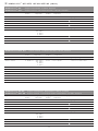
AFF
Aufputz- Feuchtefühler (± 2,0 %), Standa rd
HYGRASGARD
®
AFTF
Aufputz- Feuchte- und Temperaturfühler (± 2,0 %), Standard
Typ ⁄ WG02 Messbereich ⁄ Anzeige
Feuchte Temperatur
Ausgang
Display
Feuchte Temperatur
Art.-Nr.
AFF - xx (aktiv)
AFF-I TYR-2 0...100 % r. H. – 4...20 mA – 1201-7112-0000-000
AFF-I TYR-2 DISPLAY 0...100 % r. H. – 4...20 mA – ■ 1201-7112-0400-000
AFF-U TYR-2 0...100 % r. H. – 0 -10 V – 1201-7111-0000-000
AFF-U TYR-2 DISPLAY 0...100 % r. H. – 0 -10 V – ■ 1201-7111-0400-000
AFTF - xx (aktiv)
AFTF-I TYR 2 0...100 % r. H. –35...+75 °C
–35...+35 °C
0...+50 °C
0...+80 °C
4...20 mA 4...20 mA 1201-7112-1000-000
AFTF-I TYR 2 DISPLAY 0...100 % r. H. (4 x w ie ob en) 4...20 mA 4...20 mA ■ 1201-7112-1400-000
AFTF-U TYR-2 0...100 % r. H. (4 x w ie ob en) 0 -10 V 0 -10 V 1201-7111-1000-000
AFTF-U TYR-2 DISPLAY 0...100 % r. H. (4 x wi e o ben ) 0 -10 V 0 - 10 V ■ 1201-7111-1400-000
HYGRASGARD
®
AFTF - U xx
Aufputz- Feuchte- und Temperaturfühler (± 2,0 %)
,
Standard
Typ ⁄ WG02 Messbereich ⁄ Anzeige
Feuchte Temperatur
Ausgang
Feuchte Temperatur
Art.-Nr.
AFTF - U xx Pt, Ni, LM235Z, NTC (aktiv ⁄ passiv)
AFTF-U PT100 0...100 % r. H. –35...+75 °C
–35...+35 °C
0...+50 °C
0...+80 °C
0 -10 V 0 -10 V + Pt100 1201-7111-2001-000
AFTF-U PT1000 0...100 % r. H. (4 x w ie o be n) 0 -10 V 0 -10 V + Pt1000 1201-7111-2005-000
AFTF-U NI1000 0...100 % r. H. (4 x wi e o ben ) 0 -10 V 0 -10 V + Ni1000 1201-7111-2009-000
AFTF-U NITK 0...100 % r. H. (4 x wi e o ben ) 0 -10 V 0 -10 V + Ni1000TK5000 1201-7111-2010-000
AFTF-U LM235Z 0...100 % r. H. (4 x w ie ob en) 0 -10 V 0 -10 V + LM235Z, 10mV ⁄ K 1201-7111-2021-000
AFTF-U NTC1,8K 0...100 % r. H. (4 x wi e o ben ) 0 -10 V 0 -10 V + NTC 1,8 kOhm 1201-7111-2012-000
AFTF-U NTC10K 0...100 % r. H. (4 x w ie ob en) 0 -10 V 0 -10 V + NTC 10 kOhm 1201-7111-2015-000
AFTF-U NTC20K 0...100 % r. H. (4 x w ie ob en) 0 -10 V 0 -10 V + NTC 20 kOhm 1201-7111-2016-000
HYGRASGARD
®
AFF - SD
Aufputz- Feuchtefühler, Kompaktform (± 2,0 %), Standard
HYGRASGARD
®
AFTF - SD
Aufputz- Feuchte- und Temperaturfühler, Kompaktform (± 2,0 %), Standa rd
Typ ⁄ WG01B Messbereich ⁄ Anzeige
Feuchte Temperatur
Ausgang
Display
Feuchte Temperatur
Art.-Nr.
AFF - SD - xx (aktiv)
AFF-SD-I 0...100 % r. H. – 4...20 mA – 1201-1122-0000-100
AFF-SD-I DISPLAY 0...100 % r. H. – 4...20 mA – ■ 1201-1122-0200-000
AFF-SD-U 0...100 % r. H. – 0 -10 V – 1201-1121-0000-100
AFF-SD-U DISPLAY 0...100 % r. H. – 0 -10 V – ■ 1201-1121-0200-000
AFTF - SD - xx (aktiv)
AFTF-SD-I 0...100 % r. H. –35...+75 °C
–35...+35 °C
0...+50 °C
0...+80 °C
4...20 mA 4...20 mA 1201-1122-1000-100
AFTF-SD-I DISPLAY 0...100 % r. H. (4 x wi e o ben ) 4...20 mA 4...20 mA ■ 1201-1122-1200-100
AFTF-SD-U 0...100 % r. H. (4 x wi e o ben ) 0 -10 V 0 -10 V 1201-1121-1000-100
AFTF-SD-U DISPLAY 0...100 % r. H. (4 x wi e o ben ) 0 -10 V 0 - 10 V ■ 1201-1121-1200-100

5
D
HYGRASGARD
®
AFF - 20 ⁄ AFTF - 20, AFF - 25 ⁄ AFTF - 25 (± 1,8 %)
Zubehör
SF-M Metall
-Sinterfilter, Ø 16 mm, L = 32 mm, austauschbar,
aus Edelstahl
V4A
(1.4404)
7000-0050-2200-100
MSK-25 steckbarer Messkopf
(Fühler), aus Edelstahl
V2A
(1.4301),
Metall
-Sinterfilter, Ø 16 mm, L = 88,5 mm, austauschbar,
als Austauschelement für
AFF - 25 ⁄ AFTF - 25
7201-1131-0000-000
WS-01 Sonnen- und Ballwurfschutz
, 184 x 180 x 80 mm, aus Edelstahl
V2A
(1.4301) 7100-0040-2000-000
WS-03 Wetter- und Sonnenschutz
, 200 x 180 x 150 mm, aus Edelstahl
V2A
(1.4301) 7100-0040-6000-000
HYGRASGARD
®
AFF - 25
Aufputz- Feuchtefühler, steckbar (± 1,8 %)
,
Deluxe
HYGRASGARD
®
AFTF - 25
Aufputz- Feuchte- und Temperaturfühler, steckbar (± 1,8 %)
,
Deluxe
Typ ⁄ WG02 Messbereich ⁄ Anzeige
Feuchte Temperatur
Ausgang
Display
Feuchte Temperatur
Art.-Nr.
AFF - 25 - xx (aktiv)
AFF-25-I TYR-2 0...100 % r. H. – 4... 20 mA – 1201-7132-0000-101
AFF-25-I TYR-2 DISPLAY 0...100 % r. H. – 4... 20 mA – ■ 1201-7132-0400-101
AFF-25-U TYR-2 0...100 % r. H. – 0 -10 V – 1201-7131-0000-101
AFF-25-U TYR-2 DISPLAY 0...100 % r. H. – 0 -10 V – ■ 1201-7131-0400-101
AFTF - 25 - xx (aktiv)
AFTF-25-I TYR-2 0...100 % r. H. –35...+75 °C
–35...+35 °C
0...+50 °C
0...+80 °C
4... 20 mA 4... 20 mA 1201-7132-1000-101
AFTF-25-I TYR-2 DISPLAY 0...100 % r. H. (4 x wi e o ben ) 4... 20 mA 4... 20 mA ■ 1201-7132-1400-101
AFTF-25-U TYR-2 0...100 % r. H. (4 x w ie ob en) 0 -10 V 0 -10 V 1201-7131-1000-101
AFTF-25-U TYR-2 DISPLAY 0...100 % r. H. (4 x w ie ob en) 0 -10 V 0 - 10 V ■ 1201-7131-1400-101
HYGRASGARD
®
AFF - 20
Aufputz- Feuchtefühler, steckbar (± 1,8 %)
,
Deluxe
HYGRASGARD
®
AFTF - 20
Aufputz- Feuchte- und Temperaturfühler, steckbar (± 1,8 %)
,
Deluxe
Typ ⁄ WG02 Messbereich ⁄ Anzeige
Feuchte Temperatur
Ausgang
Display
Feuchte Temperatur
Art.-Nr.
AFF - 20 - xx (aktiv)
AFF-20-I TYR-2 0...100 % r. H. – 4... 20 mA – 1201-7112-0000-201
AFF-20-I TYR-2 DISPLAY 0...100 % r. H. – 4... 20 mA – ■ 1201-7112-0400-201
AFF-20-U TYR-2 0...100 % r. H. – 0 -10 V – 1201-7111-0000-201
AFF-20-U TYR-2 DISPLAY 0...100 % r. H. – 0 -10 V – ■ 1201-7111-0400-201
AFTF - 20 - xx (aktiv)
AFTF-20-I TYR-2 0...100 % r. H. –35...+75 °C
–35...+35 °C
0...+50 °C
0...+80 °C
4... 20 mA 4... 20 mA 1201-7112-1000-201
AFTF-20-I TYR-2 DISPLAY 0...100 % r. H. (4 x wi e o ben ) 4... 20 mA 4... 20 mA ■ 1201-7112-1400-201
AFTF-20-U TYR-2 0...100 % r. H. (4 x w ie ob en) 0 -10 V 0 -10 V 1201-7111-1000-201
AFTF-20-U TYR-2 DISPLAY 0...100 % r. H. (4 x w ie ob en) 0 -10 V 0 - 10 V ■ 1201-7111-1400-201

6
D
HYGRASGARD
®
AFF - xx ⁄ AFTF - xx
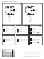
Temperatur-
Messbereiche
(einstellbar)
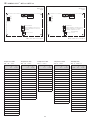
DIP
1
DIP
2
– 35 ... + 75 °C
O N O N
– 35 ... + 35 °C OFF OFF
0
...
+ 50 °C
(default) OFF
O N
0 ... + 80 °C
O N
OFF
*
2-Leiter-Anschluss für Geräte ohne ⁄ mit Display (unbeleuchtet)
3-Leiter-Anschluss für Geräte mit beleuchtetem Display
**
3-Leiter-Anschluss für Geräte ohne ⁄ mit Display (unbeleuchtet)
4-Leiter-Anschluss für Geräte mit beleuchtetem Display
Bei der I - Variante ist der Feuchte pfad zwingend anzuschließen!
4- oder 6-Leiter-
AFTF - I
Anschluss
(passiver
Temperatursensor)
4-Leiter-
AFTF - xx - U
Anschluss
3- oder 4-Leiter-
AFTF - xx - I
Anschluss** (Transmitter)
3-Leiter-
AFF - xx - U
Anschluss
2- oder 3-Leiter-
AFF - xx - I
Anschluss* (Transmitter)
4- oder 6-Leiter-
AFTF - U
Anschluss
(passiver
Temperatursensor)
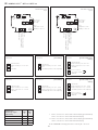
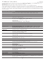
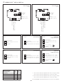
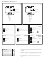
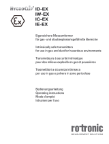
Schaltbild
AFTF - SD - U
mit ⁄ ohne Display
(Tyr1)
Schaltbild
**
AFTF - SD - I
mit ⁄ ohne Display
(Tyr1)
1
2
3
4
–UB-GND
frei
Ausgang Feuchte 0-10V in % r.H.
+UB 24V AC/DC
1
2
3
4
5
6
passives Element
–UB-GND
Ausgang Temperatur 0-10V in °C
Ausgang Feuchte 0-10V in % r.H.
+UB 24V AC/DC
z.B. Pt1000, Ni1000,
LMZ235Z
1
2
3
4
5
6
passives Element
–UB-GND (optional für
Hintergrundbeleuchtung)
Ausgang Temperatur 4...20mA in °C
Ausgang Feuchte 4...20mA in % r.H.
+UB 24V DC
z.B. Pt1000, Ni1000,
LMZ235Z
1
2
3
4
–UB-GND
Ausgang Temperatur 0-10V in °C
Ausgang Feuchte 0-10V in % r.H.
+UB 24V AC/DC
1
2
3
4
Ausgang Temperatur 4...20mA in °C
Ausgang Feuchte 4...20mA in % r.H.
+UB 24V DC
–UB-GND (optional für
Hintergrundbeleuchtung)
1
2
3
4
–UB-GND (optional für
Hintergrundbeleuchtung)
frei
Ausgang Feuchte 4...20mA in % r.H.
+UB 24V DC
1 2 3 4
5 6
1
2
0N
Offset
°C r.H.
Stecker
Display
DIP-Schalter
Mehrbereichs-
umschaltung
UB+ 24V AC/DC
Ausgang Feuchte 0-10V in % r.H.
Ausgang Temperatur 0-10V in °C
UB- GND
passiver
Sensor
Offset
Temperatur: ± 5 K
Feuchte: ± 10% r.H.
1 2 3 4
5 6
1
2
0N
Offset
°C r.H.
UB+ 24V DC
Ausgang Feuchte 4-20mA in % r.H.
Ausgang Temperatur 4-20mA in °C
UB- GND (optional für
LCD-Hintergrundbeleuchtung
Stecker
Display
passiver
Sensor
DIP-Schalter
Mehrbereichs-
umschaltung
Offset
Temperatur: ± 5 K
Feuchte: ± 10% r.H.

7
D
HYGRASGARD
®
AFF - xx ⁄ AFTF - xx
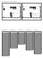
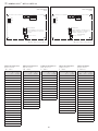
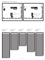
Feuchtetabelle
MB: 0 …100 % r. H.
%
r.H.
U
A
in V
I
A
in mA
0
0,0 4,0
5
0,5 4,8
10
1,0 5,6
15
1,5 6,4
20
2,0 7,2
25
2,5 8,0
30
3,0 8,8
35
3,5 9,6
40
4,0 10,4
45
4,5 11,2
50
5,0 12,0
55
5,5 12,8
60
6,0 13,6
65
6,5 14,4
70
7,0 15,2
75
7,5 16,0
80
8,0 16,8
85
8,5 17,6
90
9,0 18,4
95
9,5 19,2
100 10,0 20,0
Temperaturtabelle
MB: 0 …+80 °C
°C U
A
in V
I
A
in mA
0
0,0 4,0
5
0,6 5,0
10
1,3 6,0
15
1,9 7,0
20
2,5 8,0
25
3,1 9,0
30
3,8 10,0
35
4,4 11,0
40
5,0 12,0
45
5,6 13,0
50
6,3 14,0
55
6,9 15,0
60
7,5 16,0
65
8,1 17,0
70
8,8 18,0
75
9,4 19,0
80
10,0 20,0
Temperaturtabelle
MB: –35 …+75 °C
°C
U
A
in V
I
A
in mA
– 35
0,0 4,0
– 30
0,5 4,7
– 25
0,9 5,5
– 20
1,4 6,2
– 15
1,8 6,9
– 10
2,3 7,6
– 5
2,7 8,4
0
3,2 9,1
5
3,6 9,8
10
4,1 10,5
15
4,5 11,3
20
5,0 12,0
25
5,5 12,7
30
5,9 13,5
35
6,4 14,2
40
6,8 14,9
45
7,3 15,6
50
7,7 16,4
55
8,2 17,1
60
8,6 17,8
65
9,1 18,5
70
9,5 19,2
75
10,0 20,0
Temperaturtabelle
MB: –35 …+35 °C
°C U
A
in V
I
A
in mA
– 35
0,0 4,0
– 30
0,7 5,1
– 25
1,4 6,3
– 20
2,1 7,4
– 15
2,9 8,6
– 10
3,6 9,7
– 5
4,3 10,9
0
5,0 12,0
5
5,7 13,1
10
6,4 14,3
15
7,1 15,4
20
7,9 16,6
25
8,6 17,7
30
9,3 18,9
35
10,0 20,0
Temperaturtabelle
MB: 0 …+50 °C
°C U
A
in V
I
A
in mA
0
0,0 4,0
5
1,0 5,6
10
2,0 7,2
15
3,0 8,8
20
4,0 10,4
25
5,0 12,0
30
6,0 13,6
35
7,0 15,2
40
8,0 16,8
45
9,0 18,4
50 10,0 20,0
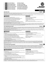
Schaltbild
AFTF - xx - U
mit Display
(Tyr2)
Schaltbild
**
AFTF - xx - I
mit Display
(Tyr2)
DIP 3, 4, 5, 6 ist nicht belegt!DIP 3, 4, 5, 6 ist nicht belegt!
1
2
5
6
3
4
123456
ON DIP
°C
offset
r.H.
Stecker
Display
Kontakt-
seite
–UB GND
+UB 24V AC/DC
Ausgang Feuchte 0-10V in % r.H.
Ausgang Temperatur 0 -10V in °C
passiver Sensor
1
2
5
6
3
4
123456
ON DIP
°C
offset
r.H.
–UB GND
(optional für LCD-
Hintergrundbeleuchtung)
+UB 24V DC
Ausgang Feuchte 4...20mA in % r.H.
Ausgang Temperatur 4...20mA in °C
Stecker
Display
Kontakt-
seite
passiver Sensor

8
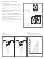
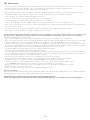
Bürdendiagramm
AFF - xx ⁄ AFTF - x x
4...20 mA
800
700
600
500
400
300
250
50
200
10 15 20 25 30 35 36 40
Bürdendiagramm
Bürde (Ohm)
Betriebsspannung (DC/V)
zulässiger
Bereich
800
700
600
500
400
300
250
50
200
10 15 20 25 30 35 36 40
Bürdendiagramm
Bürde (Ohm)
Betriebsspannung (DC/V)
zulässiger
Bereich
HINWEIS
Bei 4...20 mA Geräten ist eine Gleichspannung
zu verwenden (ohne Restwilligkeit, siehe zulässiger
Bereich des Bürdendiagramms), keine pulsierende
Gleichspannung verwenden.
Anschlussbild
AFTF - xx - U
Ausgang:
mit ⁄ ohne
0 -10 V Display
Anschlussbild
AFTF - xx - I
Ausgang: mit ⁄ ohne
4...20 mA Display
HINWEIS
Bei den Stromtransmittern muss der Feuchteausgang (Pin 2)
grundsätzlich angeschlossen werden!
1
2 3
4
230
V AC
24V AC/DC
SPS
PC
+UB 24V AC/DC
Ausgang Feuchte 0-10V in % r.H.
Ausgang Temperatur 0-10V in °C
–UB-GND
1
2 3
4
230
V AC
24
V DC
SPS
Bürde
+UB 24V DC
Ausgang Feuchte 4...20mA in % r.H.
Ausgang Temperatur 4...20mA in °C
–UB GND (optional für
LCD-Hintergrundbeleuchtung)
D
HYGRASGARD
®
AFF - xx ⁄ AFTF - xx
Schaltbild
Parallelbetrieb
Schaltbild
Einzelbetrieb
VERSORGUNGSSPANNUNG:
Als Verpolungsschutz der Betriebsspannung ist bei dieser Gerätevariante
eine Einweggleichrichtung bzw. Verpolungschutzdiode integriert. Diese
interne Einweggleichrichtung erlaubt auch den Betrieb mit AC-Versorgungs-
spannung bei 0 - 10 V Geräten.
Das Ausgangssignal ist mit einem Messgerät abzugreifen. Hierbei wird die
Ausgangsspannung gegen das Nullpotenial (O V) der Eingangsspannung ge -
messen!
Wird dieses Gerät mit
DC - Versorgungsspannung
betrieben, ist der Be-
triebsspannungseingang UB+ für 15...36 V DC - Einspeisung und UB– bzw.
GND als Masseleitung zu verwenden!
Werden mehrere Geräte von einer 24 V
AC - Spannung
versorgt, ist
darauf zu achten, dass alle „positiven“ Betriebsspannungseingänge (+) der
Feldgeräte miteinander verbunden sind, sowie alle „negativen“ Betriebs-
spannungseingänge (–) = Bezugspotential miteinander ver bunden sind (pha-
sengleicher Anschluss der Feldgeräte). Alle Feld ge räte aus gänge müssen auf
das gleiche Potential bezogen werden!
Bei Verpolung der Versorgungsspannung an einem der Feldgeräte würde
über dieses ein Kurzschluss der Versorgungsspannung erzeugt. Der somit
über dieses Feldgerät fließende Kurzschlussstrom kann zur Beschädigung
dieses Gerätes führen.
Achten Sie daher auf die korrekte Verdrahtung!
Schaltung Schaltung
0-10V
0V/GND
0-10V
0V/GND
Versorgung mit
AC 24V~ 0V
DC 15-36V = GND
AC 24V~ 0V
DC 15-36V = GND
Schaltung
0-10V
0V/GND
V
Versorgung mit

9
D
Wichtige Hinweise
– Dieses Gerät darf nur in schadstofffreier, nicht kondensierender Luft, ohne Über- oder Unterdruck am Sensorelement eingesetzt werden.
– Bei Aussen- und Kanalfühlern schützt der Sinterfilter des Sensorelementes den Feuchtesensor vor eventuellen Staub belastungen.
Dieser Filter sollte bei Verunreinigung ⁄ Verschmutzung regelmäßig gewartet werden.
– Staub- und Verunreinigungen verfälschen das Messergebnis und sind zu vermeiden.
Geringe Verunreinigungen und Staubablagerungen können mit Druckluft beseitigt werden.
– Das Berühren des Feuchteelementes ist unbedingt zu vermeiden, da dies zu erheblichen Fehlmessungen führt.
– Bei Verunreinigungen empfehlen wir eine werksseitige Reinigung und Neukalibrieung.
– Chemikalien oder andere Reinigungsmittel dürfen unter keinen Umständen auf den Sensor gelangen.
– Die relative Feuchte von 0 ...100 % wird durch das Ausgangssignal von 0 -10 V oder 4...20 mA abgebildet. Der Arbeitsbereich des Gerätes umfasst
10,0 ... 99 % r. H., ausserhalb dieses Bereiches kann es zu Fehlmessungen bzw. zu erhöhten Abweichungen kommen.
– Beim Anschluss mehrerer Fühler (0 -10 V) an eine gemeinsame Spannungsversorgung mit 24 V AC (Wechselspannung) ist auf die Polung zu achten,
da sonst die Wechselspannungsquelle kurz geschlossen werden kann.
– Die Spannungsausgänge sind kurzschlussfest, ein Anlegen einer Überspannung oder der Spannungsversorgung am Spannungsausgang zerstört das Gerät.
– Beim Betrieb des Gerätes ausserhalb des Spezifikationsbereiches entfallen alle Garantieansprüche.
Als AGB gelten ausschließlich unsere sowie die gültigen „Allgemeinen Lieferbedingungen für Erzeugnisse und Leistungen der Elektro industrie“
(ZVEI Bedingungen) zuzüglich der Ergänzungsklausel „Erweiterter Eigentumsvorbehalt“.
Außerdem sind folgende Punkte zu beachten:
– Vor der Installation und Inbetriebnahme ist diese Anleitung zu lesen und die alle darin gemachten Hinweise sind zu beachten!
– Der Anschluss der Geräte darf nur an Sicherheitskleinspannung und im spannungslosen Zustand erfolgen.
Um Schäden und Fehler am Gerät (z.B. durch Spannungsinduktion) zu verhindern, sind abgeschirmte Leitungen zu verwenden,
eine Parallelverlegung zu stromführenden Leitungen zu vermeiden und die EMV- Richtlinien zu beachten.
– Dieses Gerät ist nur für den angegebenen Verwendungszweck zu nutzen, dabei sind die entsprechenden Sicherheitsvorschriften des VDE,
der Länder, ihrer Überwachungsorgane, des TÜV und der örtlichen EVU zu beachten.
Der Käufer hat die Einhaltung der Bau- und Sicherungsbestimmung zu gewährleisten und Gefährdungen aller Art zu vermeiden.
–
Für Mängel und Schäden, die durch unsachgemäße Verwendung dieses Gerätes entstehen, werden keinerlei Gewährleistungen und Haftungen übernommen
.
– Folgeschäden, welche durch Fehler an diesem Gerät entstehen, sind von der Gewährleistung und Haftung ausgeschlossen.
– Montage und Inbetriebnahme der Geräte darf nur durch Fachpersonal erfolgen.
–
Es gelten ausschließlich die technischen Daten und Anschlussbedingungen der zum Gerät gelieferten Montage- und Bedienungs anleitung, Abweichungen zur
Katalogdarstellung sind nicht zusätzlich aufgeführt und im Sinne des technischen Fortschritts und der stetigen Verbesserung unserer Produkte möglich.
– Bei Veränderungen der Geräte durch den Anwender entfallen alle Gewährleistungsansprüche.
– Dieses Gerät darf nicht in der Nähe von Wärmequellen (z.B. Heizkörpern) oder deren Wärmestrom eingesetzt werden, eine direkte Sonnen einstrahlung
oder Wärmeeinstrahlung durch ähnliche Quellen (starke Leuchte, Halogenstrahler) ist unbedingt zu vermeiden.
– Der Betrieb in der Nähe von Geräten, welche nicht den EMV- Richtlinien entsprechen, kann zur Beeinflussung der Funktionsweise führen.
– Dieses Gerät darf nicht für Überwachungszwecke, welche dem Schutz von Personen gegen Gefährdung oder Verletzung dienen und
nicht als Not-Aus-Schalter an Anlagen und Maschinen oder vergleichbare sicherheitsrelevante Aufgaben verwendet werden.
– Die Gehäuse- und Gehäusezubehörmaße können geringe Toleranzen zu den Angaben dieser Anleitung aufweisen.
– Veränderungen dieser Unterlagen sind nicht gestattet.
– Reklamationen werden nur vollständig in Originalverpackung angenommen.
Hinweise zur Inbetriebnahme:
Dieses Gerät wurde unter genormten Bedingungen kalibriert, abgeglichen und geprüft. Bei Betrieb unter abweichenden Bedingungen empfehlen wir Vorort eine
manuelle Justage erstmals bei Inbetriebnahme sowie anschließend in regelmäßigen Abständen vorzunehmen.
Eine Inbetriebnahme ist zwingend durchzuführen und darf nur von Fachpersonal vorgenommen werden!
Vor der Montage und Inbetriebnahme ist diese Anleitung zu lesen und die alle darin gemachten Hinweise sind zu beachten!

10
G
HYGRASGARD
®
AFF - xx ⁄ AFTF - xx
Rev. 2019 - V25
SD =
Rev. 2019 - V23
Calibratable outdoor humidity ⁄ temperature sensor
HYGRASGARD
®
AFF ⁄ AFTF
(± 2.0 %
AFF - SD ⁄ AFTF - SD
(± 2,0 % ) and
AFF - 20 ⁄ AF TF - 20
(± 1.8 %) with plastic sinter filter (optional metal sinter filter) or
AFF - 25 ⁄ AFTF - 25
(± 1.8 %) with pluggable metal sinter filter;
terminal-box enclosure made of impact-resistant plastic,
with ⁄ without optional display
.
It measures the relative humidity and ⁄ or temperature of the air and converts the measurand into a standard signal of 0 - 10 V or 4...20 mA.
They have four switchable temperature ranges and are applied in non-aggressive, dust-free atmospheres in refrigeration, air conditioning, ventilation
and clean room technology. Relative humidity (in % r. H.) is the quotient of water vapour partial pressure divided by the saturation vapour pressure
at the respective gas temperature. These measuring transducers are designed for exact detection of humidity. A digital long-term stable sensor is
used as measuring element for humidity measurement. Fine adjustment by the user is possible.
TECHNICAL DATA
Power supply: 24 V AC (± 20 %); 15...36 V DC for U variant
15...36 V DC for I variant, depending on working resistance, residual ripple stabilised ± 0.3 V
Working resistance: R
a
(ohm) = (U
b
-14 V) ⁄ 0.02 A for I variant
Load resistance: R
L
> 5 kOhm for U variant
Power consumption: < 1.1 VA ⁄ 24 V DC ; < 2.2 VA ⁄ 24 V AC
Sensors:
digital humidity sensor with integrated temperature sensor,
low hysteresis, high long-term stability
Sensor protection:
AFF ⁄ AFTF, AFF - 20 ⁄ AFTF - 20, AFF - SD ⁄ AFTF - SD:
plastic
sinter filter, Ø 16 mm, L = 35 mm, exchangeable
(optional metal
sinter filter, Ø 16 mm, L = 32 mm)
AFF - 25 ⁄ AFTF - 25:
pluggable measuring head
(probe), stainless steel
V2A
(1.4301),
with metal
sinter filter, Ø 16 mm, L = 88.5 mm, exchangeable
HUMIDITY
Measuring range, humidity: 0...100 % r. H. (output corresponding to 0 -10 V or 4...20 mA)
Operating range, humidity: 0...95 % r. H. (without dew formation)
Permissible air humidity: < 95 % r. H., non-precipitating air
Deviation, humidity:
AFF ⁄ AFTF, AFF - SD ⁄ AFTF - SD:
typically
± 2.0 %
(20...80 % r. H.) at +25 °C, otherwise ± 3.0 %
AFF - 20 ⁄ AFTF - 20, AFF - 25 ⁄ AFTF - 25:
typically
± 1.8 %
(10...90 % r. H.) at +25 °C, otherwise ± 2.0 %
Output, humidity: 0 -10 V for U variant
4...20 mA for I variant, see load resistance diagram
TEMPERATURE
Measuring range,
multi-range switching
(see table)
temperature:
–35...+35 °C; –35...+75 °C; 0...+50 °C; 0...+80 °C
(output corresponding to 0 -10 V or 4...20 mA)
Ambient temperature:
AFF ⁄ AFTF, AFF - 20 ⁄ AFTF - 20, AFF - 25 ⁄ AFTF - 25:
storage –35...+85 °C; operation – 30...+80 °C, non-precipitating
AFF - SD ⁄ AFTF - SD:
storage –35...+85 °C; operation – 30...+70 °C, non-precipitatin
Deviation, temperature:
AFF ⁄ AFTF:
typically ± 0.4 K at +25 °C
AFF - 20 ⁄ AFTF - 20, AFF - 25 ⁄ AFTF - 25:
typically ± 0.2 K at +25 °C
AFF - SD ⁄ AFTF - SD:
typically ± 0.6 K at +25 °C
Output, temperature: 0 -10 V or 4...20 mA or Ohm value
Electrical connection: 2-, 3-, or 4-wire connection (see connecting diagram), 0.14 - 1.5 mm², via terminal screws
Enclosure: plastic, UV-stabilised, material polyamide, 30 % glass-globe reinforced,
with quick-locking screws (slotted ⁄ Phillips head combination),
colour traffic white (similar to RAL 9016),, enclosure cover for display is transparent!
Enclosure dimensions:
AFF ⁄ AFTF, AFF - 20 ⁄ AFTF - 20, AFF - 25 ⁄ AFTF - 25:
126 x 90 x 50 mm (Tyr 2)
AFF - SD ⁄ AFTF - SD:
72 x 64 x 37,8 mm (Tyr 1
without
Display)
72 x 64 x 43,3 mm (Tyr 1
with
display)
Cable gland: M 16 x 1.5, including strain relief, exchangeable, max. inner diameter 10.4 mm
Protective tube:
stainless steel V2A
(1.4301)
,
Ø 16 mm
AFF ⁄ AFTF, AFF - SD ⁄ AFTF - SD:
NL = 55 mm
AFF - 20 ⁄ AFTF - 20:
NL = 137 mm
AFF - 25 ⁄ AFTF - 25:
NL = 88.5 mm
Process connection: by screws
Long-term stability: ± 1 % per year
Protection class: III (according to EN 60 730)
Protection type: IP 65 (according to EN 60 529) enclosure only!
Standards: CE conformity, according to EMC directive 2014 ⁄ 30 ⁄ EU, according to EN 61326-1, according to EN 61326-2-3
Optional:
display with illumination
, for displaying ACTUAL temperature and ⁄ or ACTUAL humidity
AFF ⁄ AFTF, AFF - 20 ⁄ AFTF - 20, AFF - 25 ⁄ AFTF - 25
(Tyr 2)
: three-line
,
cutout 70 x 40 mm (W x H),
AFF -SD ⁄ AFTF - SD
(Tyr 1)
: two-line
, cutout approx. 36 x15 mm (W x H)

11
G
HYGRASGARD
®
AFF ⁄ AFTF, AFF - SD ⁄ AFTF - SD (± 2.0 %)
HYGRASGARD
®
AFF - SD
On-wall humidity sensors, compact form (± 2.0 %), Standard
HYGRASGARD
®
AFTF - SD
On-wall humidity and temperature sensors, compact form (± 2.0 %), Standard
Type ⁄ WG01B Measuring Range ⁄ Readout
Humidity
Temperature
Output
Display
Humidity Temperature
Item No.
AFF - SD - xx (active)
AFF-SD-I 0...100 % r. H. – 4...20 mA – 1201-1122-0000-100
AFF-SD-I DISPLAY 0...100 % r. H. – 4...20 mA – ■ 1201-1122-0200-000
AFF-SD-U 0...100 % r. H. – 0 -10 V – 1201-1121-0000-100
AFF-SD-U DISPLAY 0...100 % r. H. – 0 -10 V – ■ 1201-1121-0200-000
AFTF - SD - xx (active)
AFTF-SD-I 0...100 % r. H. –35...+75 °C
–35...+35 °C
0...+50 °C
0...+80 °C
4...20 mA 4...20 mA 1201-1122-1000-100
AFTF-SD-I DISPLAY 0...100 % r. H. (4 x as ab ov e) 4...20 mA 4...20 mA ■ 1201-1122-1200-100
AFTF-SD-U 0...100 % r. H. (4 x as ab ov e) 0 -10 V 0 -10 V 1201-1121-1000-100
AFTF-SD-U DISPLAY 0...100 % r. H. (4 x as ab ov e) 0 -10 V 0 - 10 V ■ 1201-1121-1200-100
HYGRASGARD
®
AFF
On-wall humidity sensors (± 2.0 %), Standard
HYGRASGARD
®
AFTF
On-wall humidity and temperature sensors (± 2.0 %), Standard
Type ⁄ WG02 Measuring Range ⁄ Readout
Humidity
Temperature
Output
Display
Humidity Temperature
Item No.
AFF - xx (active)
AFF-I TYR-2 0...100 % r. H. – 4...20 mA – 1201-7112-0000-000
AFF-I TYR-2 DISPLAY 0...100 % r. H. – 4...20 mA – ■ 1201-7112-0400-000
AFF-U TYR-2 0...100 % r. H. – 0 -10 V – 1201-7111-0000-000
AFF-U TYR-2 DISPLAY 0...100 % r. H. – 0 -10 V – ■ 1201-7111-0400-000
AFTF - xx (active)
AFTF-I TYR 2 0...100 % r. H. –35...+75 °C
–35...+35 °C
0...+50 °C
0...+80 °C
4...20 mA 4...20 mA 1201-7112-1000-000
AFTF-I TYR 2 DISPLAY 0...100 % r. H. (4 x as a bov e) 4...20 mA 4...20 mA ■ 1201-7112-1400-000
AFTF-U TYR-2 0...100 % r. H. (4 x as a bov e) 0 -10 V 0 -10 V 1201-7111-1000-000
AFTF-U TYR-2 DISPLAY 0...100 % r. H. (4 x as ab ov e) 0 -10 V 0 - 10 V ■ 1201-7111-1400-000
HYGRASGARD
®
AFTF - U xx
On-wall humidity and temperature sensors (± 2.0 %), Standard
Type ⁄ WG02 Measuring Range ⁄ Readout
Humidity
Temperature
Output
Humidity Temperature
Item No.
AFTF - U xx Pt, Ni, LM235Z, NTC (active ⁄ passive)
AFTF-U PT100 0...100 % r. H. –35...+75 °C
–35...+35 °C
0...+50 °C
0...+80 °C
0 -10 V 0 -10 V + Pt100 1201-7111-2001-000
AFTF-U PT1000 0...100 % r. H. (4 x as a bov e) 0 -10 V 0 -10 V + Pt1000 1201-7111-2005-000
AFTF-U NI1000 0...100 % r. H. (4 x as ab ov e) 0 -10 V 0 -10 V + Ni1000 1201-7111-2009-000
AFTF-U NITK 0...100 % r. H. (4 x as ab ov e) 0 -10 V 0 -10 V + Ni1000TK5000 1201-7111-2010-000
AFTF-U LM235Z 0...100 % r. H. (4 x a s a bov e) 0 -10 V 0 -10 V + LM235Z, 10mV ⁄ K 1201-7111-2021-000
AFTF-U NTC1,8K 0...100 % r. H. (4 x as ab ov e) 0 -10 V 0 -10 V + NTC 1.8 kOhm 1201-7111-2012-000
AFTF-U NTC10K 0...100 % r. H. (4 x a s a bov e) 0 -10 V 0 -10 V + NTC 10 kOhm 1201-7111-2015-000
AFTF-U NTC20K 0...100 % r. H. (4 x as a bov e) 0 -10 V 0 -10 V + NTC 20 kOhm 1201-7111-2016-000

12
G
HYGRASGARD
®
AFF - 20 ⁄ AFTF - 20, AFF - 25 ⁄ AFTF - 25 (± 1.8 %)
Accessories
SF-M Metal
sinter filter, Ø 16 mm, L = 32 mm, exchangeable
stainless steel
V4A
(1.4404)
7000-0050-2200-100
MSK-25
Pluggable
measuring head
(probe) stainless steel
V2A
(1.4301),
Metal
sinter filter, Ø 16 mm, L = 88.5 mm, exchangeable
replacement element for
AFF - 25 ⁄ AFTF - 25
7201-1131-0000-000
WS-01 Sunand ball-impact protection hood
, 184 x 180 x 80 mm,
stainless steel
V2A
(1.4301)
7100-0040-2000-000
WS-03 Weatherand sun protection hood
, 200 x 180 x 150 mm,
stainless steel
V2A
(1.4301)
7100-0040-6000-000
HYGRASGARD
®
AFF - 25
On-wall humidity sensors, pluggable (± 1.8 %), Deluxe
HYGRASGARD
®
AFTF - 25
On-wall humidity and temperature sensors, pluggable (± 1.8 %), Deluxe
Type ⁄ WG02 Measuring Range ⁄ Readout
Humidity
Temperature
Output
Display
Humidity Temperature
Item No.
AFF - 25 - xx (active)
AFF-25-I TYR-2 0...100 % r. H. – 4... 20 mA – 1201-7132-0000-101
AFF-25-I TYR-2 DISPLAY 0...100 % r. H. – 4... 20 mA – ■ 1201-7132-0400-101
AFF-25-U TYR-2 0...100 % r. H. – 0 -10 V – 1201-7131-0000-101
AFF-25-U TYR-2 DISPLAY 0...100 % r. H. – 0 -10 V – ■ 1201-7131-0400-101
AFTF - 25 - xx (active)
AFTF-25-I TYR-2 0...100 % r. H. –35...+75 °C
–35...+35 °C
0...+50 °C
0...+80 °C
4... 20 mA 4... 20 mA 1201-7132-1000-101
AFTF-25-I TYR-2 DISPLAY 0...100 % r. H. (4 x as a bo ve) 4... 20 mA 4... 20 mA ■ 1201-7132-1400-101
AFTF-25-U TYR-2 0...100 % r. H. (4 x a s a bov e) 0 -10 V 0 -10 V 1201-7131-1000-101
AFTF-25-U TYR-2 DISPLAY 0...100 % r. H. (4 x a s a bov e) 0 -10 V 0 - 10 V ■ 1201-7131-1400-101
HYGRASGARD
®
AFF - 20
On-wall humidity sensors (± 1.8 %), Premium
HYGRASGARD
®
AFTF - 20
On-wall humidity and temperature sensors (± 1.8 %), Premium
Type ⁄ WG02 Measuring Range ⁄ Readout
Humidity
Temperature
Output
Display
Humidity Temperature
Item No.
AFF - 20 - xx (active)
AFF-20-I TYR-2 0...100 % r. H. – 4... 20 mA – 1201-7112-0000-201
AFF-20-I TYR-2 DISPLAY 0...100 % r. H. – 4... 20 mA – ■ 1201-7112-0400-201
AFF-20-U TYR-2 0...100 % r. H. – 0 -10 V – 1201-7111-0000-201
AFF-20-U TYR-2 DISPLAY 0...100 % r. H. – 0 -10 V – ■ 1201-7111-0400-201
AFTF - 20 - xx (active)
AFTF-20-I TYR-2 0...100 % r. H. –35...+75 °C
–35...+35 °C
0...+50 °C
0...+80 °C
4... 20 mA 4... 20 mA 1201-7112-1000-201
AFTF-20-I TYR-2 DISPLAY 0...100 % r. H. (4 x as ab ov e) 4... 20 mA 4... 20 mA ■ 1201-7112-1400-201
AFTF-20-U TYR-2 0...100 % r. H. (4 x a s a bov e) 0 -10 V 0 -10 V 1201-7111-1000-201
AFTF-20-U TYR-2 DISPLAY 0...100 % r. H. (4 x a s a bov e) 0 -10 V 0 - 10 V ■ 1201-7111-1400-201

13
G
HYGRASGARD
®
AFF - xx ⁄ AFTF - xx
Temperature
measuring ranges
(adjustable)
DIP
1
DIP
2
– 35 ... + 75 °C
O N O N
– 35 ... + 35 °C OFF OFF
0
...
+ 50 °C
(default) OFF
O N
0 ... + 80 °C
O N
OFF
*
2-wire connection for devices with ⁄ without display (not illuminated)
3-wire connection for devices with illuminated display
**
3-wire connection for devices with ⁄ without display (not illuminated)
4-wire connection for devices with illuminated display
At the I variant the humidity path must necessarily be connected !
Schematic diagram
AFTF - SD - U
with / without display
(Tyr1)
Schematic diagram
**
AFTF - SD - I
with / without display
(Tyr1)
4- or 6-wire
AFTF - I
connection
(passive temperature
sensor)
4-wire
AFTF - xx - U
connection
3- or 4-wire
AFTF - xx - I
connection** (Transmitter)
3-wire
AFF - xx -U
connection
2- or 3-wire
AFF - xx - I
connection* (Transmitter)
4- or 6-wire
AFTF - U
connection
(passive temperature
sensor)
1
2
3
4
–UB-GND
Free
Output humidity in % r.H. 0-10V
+UB 24V AC/DC
1
2
3
4
5
6
Passive element
–UB-GND
Output temperature in °C 0-10V
Output humidity in % r.H. 0-10V
+UB 24V AC/DC
e.g. Pt1000, Ni1000,
LMZ235Z
1
2
3
4
5
6
Passive element
–UB-GND (optional for backlighting)
Output temperature in °C 4...20mA
Output humidity in % r.H. 4...20mA
+UB 24V DC
e.g. Pt1000, Ni1000,
LMZ235Z
1
2
3
4
–UB-GND
Output temperature in °C 0-10V
Output humidity in % r.H. 0-10V
+UB 24V AC/DC
1
2
3
4
Output temperature in °C 4...20mA
Output humidity in % r.H. 4...20mA
+UB 24V DC
–UB-GND (optional for backlighting)
1 2 3 4
5 6
1
2
0N
Offset
°C r.H.
Plug
display
DIP switches
multi-range
switching
UB+ 24V AC/DC
Output humidity 0-10V in % r.H.
Output temperature 0-10V in °C
UB- GND
Passive
sensor
Offset
Temperature: ± 5 K
Humidity: ± 10% r.H.
1 2 3 4
5 6
1
2
0N
Offset
°C r.H.
UB+ 24V DC
Output humidity 4 – 20 mA in % r.H.
Output temperature 4 – 20 mA in °C
UB- GND (optional for
LCD background lighting
Plug
display
Passive
sensor
DIP switches
multi-range
switching
Offset
Temperature: ± 5 K
Humidity: ± 10 % r.H.
1
2
3
4
–UB-GND (optional for backlighting)
Free
Output humidity in % r.H. 4...20mA
+UB 24V DC

14
G
HYGRASGARD
®
AFF - xx ⁄ AFTF - xx
Humidity table
MR: 0 …100 % r. H.
%
r.H.
U
A
in V
I
A
in mA
0
0.0 4.0
5
0.5 4.8
10
1.0 5.6
15
1.5 6.4
20
2.0 7.2
25
2.5 8.0
30
3.0 8.8
35
3.5 9.6
40
4.0 10.4
45
4.5 11.2
50
5.0 12.0
55
5.5 12.8
60
6.0 13.6
65
6.5 14.4
70
7.0 15.2
75
7.5 16.0
80
8.0 16.8
85
8.5 17.6
90
9.0 18.4
95
9.5 19.2
100 10.0 20.0
Temperature table
MR: 0 …+80 °C
°C U
A
in V
I
A
in mA
0
0.0 4.0
5
0.6 5.0
10
1.3 6.0
15
1.9 7.0
20
2.5 8.0
25
3.1 9.0
30
3.8 10.0
35
4.4 11.0
40
5.0 12.0
45
5.6 13.0
50
6.3 14.0
55
6.9 15.0
60
7.5 16.0
65
8.1 17.0
70
8.8 18.0
75
9.4 19.0
80
10.0 20.0
Temperature table
MR: –35 …+75 °C
°C
U
A
in V
I
A
in mA
– 35
0.0 4.0
– 30
0.5 4.7
– 25
0.9 5.5
– 20
1.4 6.2
– 15
1.8 6.9
– 10
2.3 7.6
– 5
2.7 8.4
0
3.2 9.1
5
3.6 9.8
10
4.1 10.5
15
4.5 11.3
20
5.0 12.0
25
5.5 12.7
30
5.9 13.5
35
6.4 14.2
40
6.8 14.9
45
7.3 15.6
50
7.7 16.4
55
8.2 17.1
60
8.6 17.8
65
9.1 18.5
70
9.5 19.2
75
10.0 20.0
Temperature table
MR: –35 …+35 °C
°C U
A
in V
I
A
in mA
– 35
0.0 4.0
– 30
0.7 5.1
– 25
1.4 6.3
– 20
2.1 7.4
– 15
2.9 8.6
– 10
3.6 9.7
– 5
4.3 10.9
0
5.0 12.0
5
5.7 13.1
10
6.4 14.3
15
7.1 15.4
20
7.9 16.6
25
8.6 17.7
30
9.3 18.9
35
10.0 20.0
Temperature table
MR: 0 …+50 °C
°C U
A
in V
I
A
in mA
0
0.0 4.0
5
1.0 5.6
10
2.0 7.2
15
3.0 8.8
20
4.0 10.4
25
5.0 12.0
30
6.0 13.6
35
7.0 15.2
40
8.0 16.8
45
9.0 18.4
50 10.0 20.0
Schematic diagram
AFTF - xx - U
with display
(Tyr2)
Schematic diagram
**
AFTF - xx - I
with display
(Tyr2)
DIP 3, 4, 5, 6 are not assigned!DIP 3, 4, 5, 6 are not assigned!
1
2
5
6
3
4
123456
ON DIP
°C
offset
r.H.
Plug for
display
Contact
pin side
Passive sensor
+UB 24V AC/DC
Output humidity 0-10V in % r.H.
Output temperature 0-10V in °C
–UB GND
1
2
5
6
3
4
123456
ON DIP
°C
offset
r.H.
Passive sensor
Plug for
display
Contact
pin side
+UB 24V DC
Output humidity 4...20mA in % r.H.
Output temperature 4...20mA in °C
–UB GND (optional for LCD
backlighting)

15
Load resistance diagram
AFF - xx ⁄ AFTF - x x
4... 20 mA
800
700
600
500
400
300
250
50
200
10 15 20 25 30 35 36 40
Load resistance diagram
Working resistance (Ohm)
Operating voltage (V DC)
Admissible
range
800
700
600
500
400
300
250
50
200
10 15 20 25 30 35 36 40
Load resistance diagram
Working resistance (Ohm)
Operating voltage (V DC)
Admissible
range
NOTE
For 4...20 mA devices, DC voltage must be used
(without residual ripple, see permissible range of load
resistance diagram). Do not use pulsating DC voltage.
Connecting diagram
AFTF - xx - U
Output:
with ⁄ without
0 -10 V Display
Connecting diagram
AFTF - xx - I
Output:
with ⁄ without
4...20 mA Display
NOTE
At transmitters with current output the humidity output (Pin 2)
must categorically be connected !
1
2 3
4
230
V AC
24V AC/DC
PLC
PC
+UB 24V AC/DC
Output humidity in % r.H. 0-10V
Output temperature in °C 0-10V
–UB-GND
1
2 3
4
230
V AC
24
V DC
+UB 24V DC
Output humidity in % r.H. 4...20mA
Output temperature in °C 4...20mA
PLC
Working
resistance
–UB GND (optional for
LCD background lightling)
Connecting scheme
Parallel operation
Connecting scheme
Individual operation
SUPPLY VOLTAGE:
For operating voltage reverse polarity protection, a one-way rectifier or
reverse polarity protection diode is integrated in this device variant.
This internal one-way rectifier also allows operating 0 - 10 V devices on AC
supply voltage.
The output signal is to be tapped by a measuring instrument. Output volt-
age is measured against zero potential (O V) of the input voltage!
When this device is operated on
DC supply voltage
, the operating voltage
input UB+ is to be used for 15...36 V DC supply and UB – or GND for ground
wire!
When several devices are supplied by one 24 V
AC voltage supply
, it is to
be ensured that all ”positive“ operating voltage input terminals (+) of the
field devices are connected with each other and all ”negative“ operating
voltage input terminals (–) (= reference potential) are connected together
(in-phase connection of field devices). All outputs of field devices must be
referenced to the same potential!
In case of reversed polarity at one field device, a supply voltage short-
circuit would be caused by that device. The consequential short-circuit
current flowing through this field device may cause damage to it.
Therefore, pay attention to correct wiring!
Circuitry Circuitry
0...10V
0V/GND
0...10V
0V/GND
Power supply
AC 24V~ 0V
DC 15-36V = GND
Circuitry
0...10V
0V/GND
V
Power supply
AC 24V~ 0V
DC 15-36V = GND
G
HYGRASGARD
®
AFF - xx ⁄ AFTF - xx

16
G
General notes
– This device may only be used in pollutant-free non-precipitating air without above-atmospheric or below-atmospheric pressure at the sensor element.
– On outdoor and duct sensors, the sinter filter of the senor element protects the humidity sensor against potential dust exposure.
In case of pollution ⁄ contamination, this filter should be cleaned on a regular basis.
– Dust and pollution falsify measurement results and are to be avoided. Slight pollution and dust sediments can be removed by using compressed air.
– Touching the humidity element is under any circumstances to be avoided, as that would result in considerable mismeasurements.
– In case of pollution, we recommend cleaning and recalibration in the factory.
– In any case, the sensor must not get in contact with chemicals or other cleaning agents.
– The relative humidity of 0 ...100 % is indicated by an output signal of 0 -10 V or 4...20 mA.
The device operating range covers 10.0 ... 99.9 % r. H. Outside of that range, mismeasurements or increased deviations may occur.
– When several sensors (0 -10 V) are connected to one voltage supply of 24 V AC, correct polarity must be regarded as otherwise the alternating voltage
source may be short-circuited.
– The voltage outputs are short-circuit proof. Applying overvoltage or voltage supply to the voltage output will destroy the device.
– If this device is operated beyond the specified range, all warranty claims are forfeited.
Our “General Terms and Conditions for Business“ together with the “General Conditions for the Supply of Products and Services of the Electrical and
Electronics Industry“ (ZVEI conditions) including supplementary clause “Extended Retention of Title“ apply as the exclusive terms and conditions.
In addition, the following points are to be observed:
– These instructions must be read before installation and putting in operation and all notes provided therein are to be regarded!
– Devices must only be connected to safety extra-low voltage and under dead-voltage condition. To avoid damages and errors at the device (e.g. by voltage
induction) shielded cables are to be used, laying parallel with current-carrying lines is to be avoided, and EMC directives are to be observed.
–
This device shall only be used for its intended purpose. Respective safety regulations issued by the VDE, the states, their control authorities, the TÜV and
the local energy supply company must be observed. The purchaser has to adhere to the building and safety regulations and has to prevent perils of any kind.
– No warranties or liabilities will be assumed for defects and damages arising from improper use of this device.
– Consequential damages caused by a fault in this device are excluded from warranty or liability.
– These devices must be installed and commissioned by authorised specialists.
–
The technical data and connecting conditions of the mounting and operating instructions delivered together with the device are exclusively valid. Deviations
from the catalogue representation are not explicitly mentioned and are possible in terms of technical progress and continuous improvement of our products.
– In case of any modifications made by the user, all warranty claims are forfeited.
– This device must not be installed close to heat sources (e.g. radiators) or be exposed to their heat flow.
Direct sun irradiation or heat irradiation by similar sources (powerful lamps, halogen spotlights) must absolutely be avoided.
– Operating this device close to other devices that do not comply with EMC directives may influence functionality.
– This device must not be used for monitoring applications, which serve the purpose of protecting persons against hazards or injury,
or as an EMERGENCY STOP switch for systems or machinery, or for any other similar safety-relevant purposes.
– Dimensions of enclosures or enclosure accessories may show slight tolerances on the specifications provided in these instructions.
– Modifications of these records are not permitted.
– In case of a complaint, only complete devices returned in original packing will be accepted.
Notes on commissioning:
This device was calibrated, adjusted and tested under standardised conditions. When operating under deviating conditions, we recommend performing an
initial manual adjustment on-site during commissioning and subsequently at regular intervals
.
Commissioning is mandatory and may only be performed by qualified personnel!
These instructions must be read before installation and commissioning and all notes provided therein are to be regarded!

17
F
HYGRASGARD
®
AFF - xx ⁄ AFTF - xx
Rev. 2019 - V25
SD =
Rev. 2019 - V23
Le capteur d’humidité-température étalonnable pour montage à l’extérieur
HYGRASGARD
®
AFF ⁄ AFTF
(± 2,0 %)
AFF - SD ⁄ AFTF - SD
(± 2,0 % ) et
AFF - 20 ⁄ AF TF - 20
(± 1,8 %) avec filtre fritté en matière synthétique (filtre fritté en métal en option) ou
AFF - 25 ⁄ AFTF - 25
(± 1,8 %) avec filtre fritté en métal avec tête de mesure enfichable,
boîtier de raccordement en plastique résiliente, couvercle de boîtier avec vis à fermeture rapide,
au choix avec ⁄ sans écran
.
Il mesure l'humidité relative et / ou la température et convertit la grandeur de mesure en un signal normalisé de 0 -10 V ou de 4...20 mA. Il dispose
de quatre plages de température commutables et est utilisé dans un environnement non agressif, exempt de poussières, en technique frigorifique,
de climatisation, de ventilation et de salles blanches. L’humidité relative (en % h.r.) est le quotient de la pression partielle de vapeur d’eau contenue
dans le gaz par la pression de vapeur saturante à la même température. Les convertisseurs de mesure sont conçus pour donner la mesure exacte
de l’humidité. Un capteur numérique à haute stabilité à long terme est utilisé comme élément de mesure de l’humidité. L’ajustage fin peut être
effectué par l’utilisateur.
CARACTÉRISTIQUES TECHNIQUES
Alimentation en tension: 24 V ca (± 20 %) ; 15...36 V cc pour variante U
15...36 V cc pour variante I, dépend de la charge, ondulations résiduelles stabilisées ± 0,3 V
Charge: R
a
(Ohm) = (U
b
-14 V) ⁄ 0,02 A pour variante I
Résistance de charge: R
L
> 5 kOhm pour variante U
Consommation électrique : < 1,1 VA ⁄ 24 V cc ; < 2,2 VA ⁄ 24 V ca
Capteurs :
capteur d'humidité numérique avec capteur de température intégré,
petite hystérésis, stabilité à long terme
Protection de capteur :
AFF ⁄ AFTF, AFF - 20 ⁄ AFTF - 20, , AFF - SD ⁄ AF TF - SD :
filtre fritté en matière
synthétique
, Ø 16 mm, L = 35 mm, remplaçable
(en option filtre fritté en métal, Ø 16 mm, L = 32 mm)
AFF - 25 ⁄ AFTF - 25 :
tête de mesure enfichable
(sonde) en acier inox
V2A
(1.4301)
avec filtre fritté en métal, Ø 16 mm, L = 88,5 mm, remplaçable
HUMIDITÉ
Plage de mesure humidité : 0...100 % h.r. (sortie correspond à 0 -10 V ou 4...20 mA)
Plage de service humidité : 0...95 % h.r. (sans condensation)
Humidité d’air admissible : < 95 % h.r., sans condensation de l’air
Incertitude de mesure
AFF ⁄ AFTF, AFF - SD ⁄ AFTF - SD :
humidité : typique
± 2,0 %
(20...80 % h.r.) à +25 °C, sinon ± 3,0 %
AFF - 20 ⁄ AFTF - 20, AFF - 25 ⁄ AFTF - 25 :
typique
± 1,8 %
(10...90 % h.r.) à +25 °C, sinon ± 2,0 %
Sortie humidité : 0 -10 V pour variante U
4...20 mA pour variante I, voir diagramme de charge
TEMPÉRATURE
Plage de mesure température :
commutation multi-gamme
(voir tableau)
–35...+35 °C; –35...+75 °C; 0...+50 °C; 0...+80 °C
(sortie correspond à 0 -10 V ou 4...20 mA)
Température ambiante :
AFF ⁄ AFTF, AFF - 20 ⁄ AFTF - 20, AFF - 25 ⁄ AFTF - 25 :
stockage –35...+85 °C, fonctionnement – 30...+80 °C, sans condensation
AFF - SD ⁄ AFTF - SD :
stockage –35...+85 °C, fonctionnement –30...+70 °C, sans condensation
Incertitude de
AFF ⁄ AFTF:
typique ± 0,4 K à +25 °C
mesure température :
AFF - 20 ⁄ AFTF - 20, AFF - 25 ⁄ AFTF - 25:
typique ± 0,2 K à +25 °C
AFF - SD ⁄ AFTF - SD:
typique ± 0,6 K à +25 °C
Sortie température : 0 -10 V ou 4...20 mA ou valeur ohmique
Raccordement électrique : 2, 3, ou 4 fils (voir schéma de raccordement), 0,14 - 1,5 mm², par bornes à vis
Boîtier: plastique, stabilisé contre UV, matière polyamide, renforcé à 30 % de billes de verre,
avec vis de fermeture rapide (association fente ⁄ fente en croix),
couleur blanc signalisation (similaire à RAL 9016). Le couvercle de l’écran est transparent !
Dimensions du boîtier :
AFF ⁄ AFTF, AFF - 20 ⁄ AFTF - 20, AFF - 25 ⁄ AFTF - 25:
126 x 90 x 50 mm (Tyr 2)
AFF - SD ⁄ AFTF - SD:
72 x 64 x 37,8 mm (Tyr 1
sans
écran)
72 x 64 x 43,3 mm (Tyr 1
avec
écran))
Presse-étoupe : M 16 x 1,5 ; avec décharge de traction, remplaçable, diamètre intérieur max. 10,4 mm
Tube de protection :
en acier inox V2A
(1.4301)
,
Ø 16 mm,
AFF ⁄ AFTF, AFF - SD ⁄ AFTF - SD :
Ln = 55 mm
AFF - 20 ⁄ AFTF - 20 :
Ln = 137 mm
AFF - 25 ⁄ AFTF - 25 :
Ln = 88,5 mm
Raccordement process : par vis
Stabilité à long terme : ± 1 % ⁄ an
Classe de protection : III (selon EN 60 730)
Indice de protection : IP 65 (selon EN 60 529) boîtier uniquement
Normes : conformité CE selon Directive « CEM » 2014 ⁄ 30 ⁄ EU, selon EN 61326-1, selon EN 61326-2-3
En option :
écran avec rétro-éclairage,
pour afficher la température effective et ⁄ ou l’humidité effective
AFF ⁄ AFTF, AFF - 20 ⁄ AFTF - 20, AFF - 25 ⁄ AFTF - 25
(Tyr 2)
:
à
trois lignes
, découpe env. 70 x 40 mm (l x h),
AFF -SD ⁄ AFTF - SD
(Tyr 1)
:
à
deux lignes
, découpe env. 36 x15 mm (l x h)

18
F
HYGRASGARD
®
AFF ⁄ AFTF, AFF - SD ⁄ AFTF - SD (± 2,0 %)
HYGRASGARD
®
AFF
Sonde d’humidité pour montage en saillie (± 2,0 %), Standard
HYGRASGARD
®
AFTF
Sonde d’humidité et de température pour montage en saillie (± 2,0 %), Stand ard
Type ⁄ WG02 plage de mesure ⁄ affichage
humidité
température
sortie
écran
humidité température
référence
AFF - xx (actif)
AFF-I TYR-2 0...100 % h.r. – 4...20 mA – 1201-7112-0000-000
AFF-I TYR-2 DISPLAY 0...100 % h.r. – 4...20 mA – ■ 1201-7112-0400-000
AFF-U TYR-2 0...100 % h.r. – 0 -10 V – 1201-7111-0000-000
AFF-U TYR-2 DISPLAY 0...100 % h.r. – 0 -10 V – ■ 1201-7111-0400-000
AFTF - xx (actif)
AFTF-I TYR 2 0...100 % h.r. –35...+75 °C
–35...+35 °C
0...+50 °C
0...+80 °C
4...20 mA 4...20 mA 1201-7112-1000-000
AFTF-I TYR 2 DISPLAY 0...100 % h.r. (4 x comme plus haut) 4...20 mA 4...20 mA ■ 1201-7112-1400-000
AFTF-U TYR-2 0...100 % h.r. (4 x comme plus haut) 0 -10 V 0 -10 V 1201-7111-1000-000
AFTF-U TYR-2 DISPLAY 0...100 % h.r. (4 x comme plus haut) 0 -10 V 0 - 10 V ■ 1201-7111-1400-000
HYGRASGARD
®
AFTF - U xx
Sonde d’humidité et de température (± 2,0 %), Standard
Type ⁄ WG02 plage de mesure ⁄ affichage
humidité
température
sortie
humidité température
référence
AFTF - U xx Pt, Ni, LM235Z, NTC (actif ⁄ passif)
AFTF-U PT100 0...100 % h.r. –35...+75 °C
–35...+35 °C
0...+50 °C
0...+80 °C
0 -10 V 0 -10 V + Pt100 1201-7111-2001-000
AFTF-U PT1000 0...100 % h.r. (4 x comme plus haut) 0 -10 V 0 -10 V + Pt1000 1201-7111-2005-000
AFTF-U NI1000 0...100 % h.r. (4 x comme plus haut) 0 -10 V 0 -10 V + Ni1000 1201-7111-2009-000
AFTF-U NITK 0...100 % h.r. (4 x comme plus haut) 0 -10 V 0 -10 V + Ni1000TK5000 1201-7111-2010-000
AFTF-U LM235Z 0...100 % h.r. (4 x comme plus haut) 0 -10 V 0 -10 V + LM235Z, 10mV ⁄ K 1201-7111-2021-000
AFTF-U NTC1,8K 0...100 % h.r. (4 x comme plus haut) 0 -10 V 0 -10 V + NTC 1,8 kOhm 1201-7111-2012-000
AFTF-U NTC10K 0...100 % h.r. (4 x comme plus haut) 0 -10 V 0 -10 V + NTC 10 kOhm 1201-7111-2015-000
AFTF-U NTC20K 0...100 % h.r. (4 x comme plus haut) 0 -10 V 0 -10 V + NTC 20 kOhm 1201-7111-2016-000
HYGRASGARD
®
AFF - SD
Sonde d’humidité pour montage en saillie, forme compacte (± 2,0 %), Standard
HYGRASGARD
®
AFTF - SD Sonde d’humidité et de température pour montage en saillie, forme compacte (± 2,0 %), Sta ndard
Type ⁄ WG01B plage de mesure ⁄ affichage
humidité
température
sortie
écran
humidité température
référence
AFF - SD - xx (actif)
AFF-SD-I 0...100 % h.r. – 4...20 mA – 1201-1122-0000-100
AFF-SD-I DISPLAY 0...100 % h.r. – 4...20 mA – ■ 1201-1122-0200-000
AFF-SD-U 0...100 % h.r. – 0 -10 V – 1201-1121-0000-100
AFF-SD-U DISPLAY 0...100 % h.r. – 0 -10 V – ■ 1201-1121-0200-000
AFTF - SD - xx (actif)
AFTF-SD-I 0...100 % h.r. –35...+75 °C
–35...+35 °C
0...+50 °C
0...+80 °C
4...20 mA 4...20 mA 1201-1122-1000-100
AFTF-SD-I DISPLAY 0...100 % h.r. (4 x comme plus haut) 4...20 mA 4...20 mA ■ 1201-1122-1200-100
AFTF-SD-U 0...100 % h.r. (4 x comme plus haut) 0 -10 V 0 -10 V 1201-1121-1000-100
AFTF-SD-U DISPLAY 0...100 % h.r. (4 x comme plus haut) 0 -10 V 0 - 10 V ■ 1201-1121-1200-100

19
F
HYGRASGARD
®
AFF - 20 ⁄ AFTF - 20, AFF - 25 ⁄ AFTF - 25 (± 1,8 %)
Accessoires
SF-M
filtre fritté en
métal
, Ø 16 mm, L = 32 mm, remplaçable en acier inox
V4A
(1.4404) 7000-0050-2200-100
MSK-25 tête de mesure
(sonde) enfichable, en acier inox
V2A
(1.4301),
filtre fritté en
métal
, Ø 16 mm, L = 88,5 mm, remplaçable,
élément interchangeable pour
AFF - 25 ⁄ AFTF - 25
7201-1131-0000-000
WS-01 protection contre le soleil et pare-balle,
184 x 180 x 80 mm, en acier inox
V2A
(1.4301) 7100-0040-2000-000
WS-03 protection contre le soleil et les intempéries,
200 x 180 x 150 mm,
en acier inox
V2A
(1.4301)
7100-0040-6000-000
HYGRASGARD
®
AFF - 20
Sonde d’humidité pour montage en saillie (± 1,8 %), Premium
HYGRASGARD
®
AFTF - 20
Sonde d’humidité et de température pour montage en saillie (± 1,8 %), Premium
Type ⁄ WG02 plage de mesure ⁄ affichage
humidité
température
sortie
écran
humidité température
référence
AFF - 20 - xx (actif)
AFF-20-I TYR-2 0...100 % h.r. – 4... 20 mA – 1201-7112-0000-201
AFF-20-I TYR-2 DISPLAY 0...100 % h.r. – 4... 20 mA – ■ 1201-7112-0400-201
AFF-20-U TYR-2 0...100 % h.r. – 0 -10 V – 1201-7111-0000-201
AFF-20-U TYR-2 DISPLAY 0...100 % h.r. – 0 -10 V – ■ 1201-7111-0400-201
AFTF - 20 - xx (actif)
AFTF-20-I TYR-2 0...100 % h.r. –35...+75 °C
–35...+35 °C
0...+50 °C
0...+80 °C
4... 20 mA 4... 20 mA 1201-7112-1000-201
AFTF-20-I TYR-2 DISPLAY 0...100 % h.r. (4 x comme plus haut) 4... 20 mA 4... 20 mA ■ 1201-7112-1400-201
AFTF-20-U TYR-2 0...100 % h.r. (4 x comme plus haut) 0 -10 V 0 -10 V 1201-7111-1000-201
AFTF-20-U TYR-2 DISPLAY 0...100 % h.r. (4 x comme plus haut) 0 -10 V 0 - 10 V ■ 1201-7111-1400-201
HYGRASGARD
®
AFF - 25
Sonde d’humidité pour montage en saillie, enfichable (± 1,8 %), Deluxe
HYGRASGARD
®
AFTF - 25
Sonde d’humidité et de température pour montage en saillie, enfichable (± 1,8 %), Deluxe
Type ⁄ WG02 plage de mesure ⁄ affichage
humidité
température
sortie
écran
humidité température
référence
AFF - 25 - xx (actif)
AFF-25-I TYR-2 0...100 % h.r. – 4... 20 mA – 1201-7132-0000-101
AFF-25-I TYR-2 DISPLAY 0...100 % h.r. – 4... 20 mA – ■ 1201-7132-0400-101
AFF-25-U TYR-2 0...100 % h.r. – 0 -10 V – 1201-7131-0000-101
AFF-25-U TYR-2 DISPLAY 0...100 % h.r. – 0 -10 V – ■ 1201-7131-0400-101
AFTF - 25 - xx (actif)
AFTF-25-I TYR-2 0...100 % h.r. –35...+75 °C
–35...+35 °C
0...+50 °C
0...+80 °C
4... 20 mA 4... 20 mA 1201-7132-1000-101
AFTF-25-I TYR-2 DISPLAY 0...100 % h.r. (4 x comme plus haut) 4... 20 mA 4... 20 mA ■ 1201-7132-1400-101
AFTF-25-U TYR-2 0...100 % h.r. (4 x comme plus haut) 0 -10 V 0 -10 V 1201-7131-1000-101
AFTF-25-U TYR-2 DISPLAY 0...100 % h.r. (4 x comme plus haut) 0 -10 V 0 - 10 V ■ 1201-7131-1400-101

20
F
HYGRASGARD
®
AFF - xx ⁄ AFTF - xx
Plages de mesure
de température
(réglables)
DIP
1
DIP
2
– 35 ... + 75 °C
O N O N
– 35 ... + 35 °C OFF OFF
0
...
+ 50 °C
(default) OFF
O N
0 ... + 80 °C
O N
OFF
*
Raccordement 2 fils pour appareils sans ⁄ avec écran (non éclairé)
Raccordement 3 fils pour appareils avec écran rétro-éclairé
**
Raccordement 3 fils pour appareils sans ⁄ avec écran (non éclairé)
Raccordement 4 fils pour appareils avec écran rétro-éclairé
Pour la variante I, il faut impérativement raccorder la sortie humidité.
Raccordement
AFTF - I
4 ou 6 fils
(capteur de
température passif)
Raccordement
AFTF - xx - U
4 fils
Raccordement
AFTF x x - I
3 ou 4 fils** (transmetteur)
Raccordement
AFF - xx -U
3 fils
Raccordement
AFF - xx - I
2 ou 3 fils* (transmetteur)
Raccordement
AFTF - U
4 ou 6 fils
(capteur de
température passif)
1
2
3
4
–UB-GND
Free
Output humidity in % r.H. 0-10V
+UB 24V AC/DC
1
2
3
4
5
6
Passive element
–UB-GND
Output temperature in °C 0-10V
Output humidity in % r.H. 0-10V
+UB 24V AC/DC
e.g. Pt1000, Ni1000,
LMZ235Z
1
2
3
4
5
6
Passive element
–UB-GND (optional for backlighting)
Output temperature in °C 4...20mA
Output humidity in % r.H. 4...20mA
+UB 24V DC
e.g. Pt1000, Ni1000,
LMZ235Z
1
2
3
4
–UB-GND
Output temperature in °C 0-10V
Output humidity in % r.H. 0-10V
+UB 24V AC/DC
1
2
3
4
Output temperature in °C 4...20mA
Output humidity in % r.H. 4...20mA
+UB 24V DC
–UB-GND (optional for backlighting)
Schéma de raccordement
AFTF - SD - U
avec ⁄ sans écran
(Tyr1)
Schéma de raccordement
**
AFTF - SD - I
avec ⁄ sans écran
(Tyr1)
1 2 3 4
5 6
1
2
0N
Offset
°C r.H.
Plug
display
DIP switches
multi-range
switching
UB+ 24V AC/DC
Output humidity 0-10V in % r.H.
Output temperature 0-10V in °C
UB- GND
Passive
sensor
Offset
Temperature: ± 5 K
Humidity: ± 10% r.H.
1 2 3 4
5 6
1
2
0N
Offset
°C r.H.
UB+ 24V DC
Output humidity 4 – 20 mA in % r.H.
Output temperature 4 – 20 mA in °C
UB- GND (optional for
LCD background lighting
Plug
display
Passive
sensor
DIP switches
multi-range
switching
Offset
Temperature: ± 5 K
Humidity: ± 10 % r.H.
1
2
3
4
–UB-GND (optional for backlighting)
Free
Output humidity in % r.H. 4...20mA
+UB 24V DC
La page est en cours de chargement...
La page est en cours de chargement...
La page est en cours de chargement...
La page est en cours de chargement...
La page est en cours de chargement...
La page est en cours de chargement...
La page est en cours de chargement...
La page est en cours de chargement...
La page est en cours de chargement...
La page est en cours de chargement...
La page est en cours de chargement...
La page est en cours de chargement...
-
 1
1
-
 2
2
-
 3
3
-
 4
4
-
 5
5
-
 6
6
-
 7
7
-
 8
8
-
 9
9
-
 10
10
-
 11
11
-
 12
12
-
 13
13
-
 14
14
-
 15
15
-
 16
16
-
 17
17
-
 18
18
-
 19
19
-
 20
20
-
 21
21
-
 22
22
-
 23
23
-
 24
24
-
 25
25
-
 26
26
-
 27
27
-
 28
28
-
 29
29
-
 30
30
-
 31
31
-
 32
32


S+S Regeltechnik HYDRASGARD AFTF-20-I VA Operating Instructions, Mounting & Installation
- Taper
- Operating Instructions, Mounting & Installation
Documents connexes


Autres documents
-
 Prime-Line R 7132 Mode d'emploi
-
itsensor RHEASREG SW Manuel utilisateur
-
Carel SPKD005N0 Manuel utilisateur
-
Novus OfficeLight Deluxe 1 Mode d'emploi
-
Buhler RC 1.1 Quick Manual
-
 Rockwell Automation 1606-XLS180 Manuel utilisateur
-
 Rotronic ATEX Le manuel du propriétaire
-
WIKA A2G-70 Mode d'emploi
-
 AB Quality 1606-XLS480 Manuel utilisateur
-
Vaisala HMD70 Manuel utilisateur


