SBC PCS1.C8xx Mounting Instructions & Users Guide
- Taper
- Mounting Instructions & Users Guide

Saia-Burgess Controls AG
Bahnhofstrasse 18
|
CH-3280 Murten
|
Switzerland
T +41 26 580 30 00
|
F +41 26 580 34 99
www.saia-pcd.com
|
Support www.sbc-support.com
|
www.saia-pcd.com www.saia-pcd.com
PCS1.C8xx PCS1.C8xx
Overview PCS1.C8xx
Übersicht PCS1.C8xx
Récapitulatif PCS1.C8xx
Block Pin Name I/O address Notes
X1 1
2
3
Data_Sbus
/Data_Sbus
GND
Port #3, RS-485
S-Bus
Standard Port
on all PCS1
X3 4 +5V
5 n.c.
Port #2, RS-232
External display.
Standard port
on all
PCS1.C822 and
PCS1.C823
6 GND
7 CTS2_ext
8 RxD2_ext
9 RTS2_ext
10 TxD2_ext
X2 1
2
3
4
LON A Data
LON B Data
GND
LonWorks
®
X4 1 GND
Port #1
Optional port
RS-485/RS-422/
RS-232
2 I1A
3 I1B
4 I1C
5 I1D
6 I1G
X5 1 COM
GND for Pt/Ni 1000
1
)
3 E48 I 48 ch 0
I 48 ch 1
I 48 ch 2
I 48 ch 3
Inputs 0…10 V
or digital
Inputs 24 VDC
5 E49
7 E50
9 E51
11 GND
Base address = 48
see also FBox
PCS1.W2xx
13 GND
I 48 ch 4
I 48 ch 5
I 48 ch 6
I 48 ch 7
15 E52
17 E53
Pt/Ni 1000
19 E54
21 E55
X5 2 COM
GND for Pt/Ni 1000
1
)
4 E64
I 64 ch 0
I 64 ch 1
I 64 ch 2
I 64 ch 3
I 64 ch 4
I 64 ch 5
I 64 ch 6
I 64 ch 7
6 E65
Pt/Ni 1000
8 E66
10 E67
12 GND
Base address = 64
see also FBox
PCS1.W3xx
14 GND
16 E68
18 E69
20 E70
22 E71
X6 1 E0 I 0
I 1
I 2
I 3
I 4
I 5
I 6
I 7
I 8
3 E1
5 E2
7 E3
Digital
inputs, 8 ms
as PCD2.E110
9 E4
11 E5
13 E6
15 E7
17 E8
19 E9 I 9
Digital
inputs, 0.2 ms
as PCD2.E111
21 E10 I 10
23 E11 I 11
24 GND
Block Pin Name I/O address Notes
X6 2 GND
Outputs 0…10 V
¹)
4 A80 O 80 ch 0
6 A81 O 80 ch 1
Base address = 80
see also FBox
PCS1.W4xx
8 A82 O 80 ch 2
10 A83 O 80 ch 3
12 GND
Selectable as
digital inputs
(as PCD2.B100)
(I 12…I 15) or as
digital outputs
(O 12…O 15)
14 +24V_EXT
16 E/A12 I/O 12
18 E/A13 I/O 13
20 E/A14 I/O 14
22 E/A15 I/O 15
(24) GND
X7 1 Uin +24 VDC
Power supply
(inc. 24 VDC)
for relays
2 GND
3 GND
X8
1
NO20 O 20 1. Relay ²) /open
2
COM20 common
3
NC20 O 20 closed
4
NO21 O 21 2. Relay ²) /open
5
COM21 common
6
NC21 O 21 closed
7
NO22 O 22 3. Relay ²) /open
8
COM22 common
9
NC22 O 22 closed
10
NO23 O 23 4. Relay ²) /open
11 COM23 common
12 NC23 O 23 closed
X9
1
COM16 5. Relay ²) /common
2
NO16 O 16 open
3
COM17 6. Relay ²) /common
4
NO17 O 17 open
5
COM18 7. Relay ²) /common
6
NO18 O 18 open
7
COM19 8. Relay ²) /common
8
NO19 O 19 open
Intern A_M16 I 24 Switch pos.1
Intern A_M17 I 25
Intern A_M18 I 26
Intern A_M19 I 27
Intern A_M20 I 28
Acknowledgement
of manual/
Intern A_M21 I 29 emergency control
Intern A_M22 I 30 level
Intern A_M23 I 31 (Auto/Man = 1/0)
3
)
Intern A_M80_0 I 32 Switch pos.1
Intern A_M80_1 I 33
Intern A_M80_2 I 34
Intern A_M80_3 I 35
1
) extra filtered
2
) With manual/emergency control level as option
3
) Caution: If the manual/emergency control level is not equipped,
the status of inputs I24 to I35 is always logical “1”.
M4
(6)
204
195
150
78
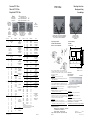
Dimension drawing
Massbild
Schémas cotés
Device depth: 60 mm
Gerätetiefe: 60 mm
Profondeur: 60 mm
Mounting instruction
Montageanleitung
Assemblage
Wall-mounting as option
Wandmontage als Option
Montage mural en option
(4’109’4849’0)
Standard mounting on 35 mm top-hat rail DIN EN 60715
Standard-Montage auf 35 mm-Hutschiene DIN EN 60715
Montage classique sur rail 35 mm DIN EN 60715
For more details, see Technical Information P+P26/345.
Weitere Informationen, siehe TI P+P26/345.
Pour tous détails, consulter l’information technique P+P26/345.
Mounting with the enclosed screws.
Befestigung mit den beiliegenden Schrauben.
Montage avec les visses fournies.
Terminal cover
Klemmenabdeckung
Capot cache-bornes 4’111’4927’0
Plug-in spring terminals
Steckbare Federkraftklemmen
Bornier à ressort embrochable
The process input terminals are up to 1.0 mm² and the proc-
ess output terminals are up to 1.5 mm². Process cable must
be bared along 7…8 mm (1.0 mm²) or 10 mm (1.5 mm²) and
inserted in the terminals.
UL Compliance:
For use of 60/75 °C copper (Cu) wire only.
IMPORTANT: Screwdrivers used should be type SDI 0.4 × 2.5 × 80
(max. width 2.5 mm).
Die Prozess-Eingangsklemmen sind bis 1.0 mm² und die
Prozess-Ausgangsklemmen bis 1.5 mm² ausgelegt. Die Pro-
zesskabel müssen 7…8 mm (1.0 mm²) bzw. 10 mm (1.5 mm²)
abisoliert und in die Klemmen gesteckt werden.
UL-konformer Einsatz:
Nur 60/75 °C Kupferleiter (Cu) verwenden.
WICHTIG: Schraubendreher des Typs SDI 0.4 × 2.5 × 80 ver-
wenden (max. Breite von 2.5 mm).
Leur section maximale est de 1 mm² pour les entrées et de
1.5 mm² pour les sorties. Le câble de raccordement côte
PCS doit être dénudé sur 7 à 8 mm (1 mm²) ou 10 mm
(1.5 mm²), puis être inséré dans les bornes.
Conformité UL :
N’utiliser que des fils de cuivre (Cu) 60/75 °C.
IMPORTANT: utiliser un tournevis du type SDI 0.4 × 2.5 × 80
(largeur max. 2.5 mm) pour ouvrir les ressorts.
X9
X9
X5
X6
X7 X9
X8
X1 / X3
X2
X4
X5 1…4 digital inputs and/or
1…4 analogue inputs 0…10 V
8 analogue inputs Pt/Ni 1000 (12 Bit)
4 analogue inputs Pt/Ni 1000 (10 Bit)
X6 12 digital inputs
4 analogue outputs 0…10 V
1…4 digital inputs and/or
1…4 digital outputs
X7
24 VDC
X9
4 relay outputs
(’make’ contact)
X8
4 relay outputs
(changeover)
X1 Port 3
RS-485 for S-Bus
or point-to-point
in MC mode
X3 Port 2
RS-232 for S-Bus,
external display or
point-to-point
X4 Port 1
Communications
PCD7.F1xxS at space A
as option
UL Compliance:
Ambient temperature operation max. 55 °C
UL-konformer Einsatz:
Umgebungstemperatur Betrieb max. 55 °C
Conformité UL :
Température ambiante de service 55 °C maxi
4’319’5025’0 g 04.2015
Subject to change without notice
PCS1.C8xx
X2
LonWorks
®
with
PCS1.C880
PCS1.C881
PCS1.C882
PCS1.C883

www.saia-pcd.com www.saia-pcd.com
PCS1.C8xx PCS1.C8xx
1 15
16
17
18
19
20
21
222
3
4
5
10
11
12
13
14
0…10 V
+ –
GND
6 8
7 9
COMCOM
1 2 3 4
X2
LON A Data
LON B Data
GND
LonWorks
®
– PCS1.C880…C883
Communication Interfaces PCS1.C8xx
Kommunikations-Schnittstellen PCS1.C8xx
Interfaces de communication PCS1.C8xx
Pins on terminal block X4 for PCD7.F1x0 communications modules at space A
Pin PCD7.F110S PCD7.F110S PCD7.F121S PCD7.F150S PCD7.F180S
RS-485 RS-422 RS-232 RS-485 *g.i. MP-Bus *g.i. = galvanically isolated
1 (gnd) GND GND GND — GND MP-Bus GND
2 (I1A) RX - TX TX TX RX - TX A-COM MP-Bus signal line
3 (I1B) /RX - /TX /TX RX /RX - /TX MST BELIMO
®
programming unit
4 (I1C) — RX RTS — IN BELIMO
®
programming unit detection
5 (I1D) — /RX CTS — GND BELIMO
®
programming unit GND
6 (I1G) — — — SGND —
1 2 3 4 5 6
GND
TX
/TX
RX
/RX
X4 (Port #1)
PCD7.F110S – RS-422
1 2 3 4 5 6
GND
+5
V DTR
TX
RX
RTS
CTS
X4 (Port #1)
1 2 3 4 5 6 7 8 9 10
X1 X3
PCD7.F121S – EIB/RS-232
1 2 3 4 5 6
GND
A-COM
MST
IN
GND
X4 (Port #1)
PCD7.F180S – BELIMO
®
MP-Bus
≤ 8 MFT/MFT2
(see 26/342)
GND
Plus +5V
TXD
RXD
/RTS
/CTS
X3 (Port #2)
X1
Minus –10V
1 2 3 4 5 6 7 8 9 10
Display PCD7.D230/RS-232 (C822 & C823)
1 2 3 4 5 6
GND
TX
RX
RTS
CTS
X4 (Port #1)
PCD7.F121S – RS-232
1 2 3 4 5 6
GND
RX-TX
/RX-/TX
X4 (Port #1)
1 2 3 4 5 6 7 8 9 10
X1 (Port #3)
X3
GND
/Data - S-Bus
Data - S-Bus
S-Bus/RS-485 PCD7.F110S – S-Bus/RS-485
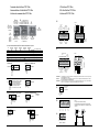
I/O Interfaces PCS1.C8xx
E/A-Schnittstellen PCS1.C8xx
Interfaces d’E/S PCS1.C8xx
X5
Details
24 VDC
COM = Ground
for all 12 bits
sensor inputs
Inputs
10 bits
1
2
3
4
5
6
7
8
9
10
11
12
13
14
15
16
17
18
19
20
21
22
COM
CH0
CH1
CH2
CH3
GND
GND
CH4
CH5
CH6
CH7
COM
CH0
CH1
CH2
CH3
GND
GND
CH4
CH5
CH6
CH7
Base-
address
48
0…10 V or
24 VDC
Pt/Ni 1000
Base-
address
64
Pt/Ni 1000Pt/Ni 1000
{
{
{
{
X8
1
2
3
4
5
6
7
8
9 10
11
12
ON
MOC
CN
ON
MOC
CN
ON
MOC
CN
ON
MOC
CN
O 20
(4 A)
O 21
(4 A)
O 22
(2 A)
O 23
(2 A)
1 2 3 4 5 6 7 8
MO
C
ON
MO
C
ON
MO
C
ON
MO
C
ON
O 16
(2 A)
O 17
(2 A)
O 18
(4 A)
O 19
(4 A)
X9
1 21 2 3
12
Details
2-stage fan controller with mutual latching
2-stufige Ventilatorsteuerung mit gegenseitiger Verriegelung
Commande de ventilateur bivitesse avec verrouillage des sorties
entre elles.
X8 X9
220 VAC
Stage 2 Stage 1
X6
IMPORTANT If combined I/Os 12…15 are used as outputs, an external supply is required (24 VDC external). In such cases only source ope-
ration will be possible at the inputs.
WICHTIG Werden kombinierte E/A 12…15 als Ausgänge verwendet, ist eine externe Speisung erforderlich (24 VDC extern). In diesem
Fall ist bei den Eingängen nur Quellbetrieb möglich.
IMPORTANT Des qu’une des 4 I/O mixt 12…15 est utilisée comme sortie, une alimentation externe de 24 VCC est néssesaire à la borne 14.
Dans ce cas, seul le fonctionnement en logique positive est possible pour les autres entrées.
Details
1
2
3
4
5
12
13
14
15
16
17
18
19
GND
GND
+
–
0…10 V
Digital inputs in
source mode
Analogue
outputs
Digital
outputs
24 VDC
external
24 VDC
1
2
3
4
5
6
7
8
9
10
11
12
13
14
15
16
17
18
19
20
21
22
23
I0
I1
I2
I3
I4
I5
I6
I7
I8
I9
I10
I11
GND
CH0
CH1
CH2
CH3
GND
I/O12
I/O13
I/O14
I/O15
GND
24
0 …10 V
Base address 80
Digitale In-/
outputs
24 VDC ext.
Digital inputs 24 VDC
8 ms
0.2 ms
{
{
{
{
X9
X9
X5
X6
X7 X9
X8
X1 / X3
X2
X4
X5 1…4 digital inputs and/or
1…4 analogue inputs 0…10 V
8 analogue inputs Pt/Ni 1000 (12 Bit)
4 analogue inputs Pt/Ni 1000 (10 Bit)
X6 12 digital inputs
4 analogue outputs 0…10 V
1…4 digital inputs and/or
1…4 digital outputs
X7
24 VDC
X9
4 relay outputs
(’make’ contact)
X8
4 relay outputs
(changeover)
X2
LonWorks
®
with
PCS1.C880
PCS1.C881
PCS1.C882
PCS1.C883
X1 Port 3
RS-485 for S-Bus
or point-to-point
in MC mode
X3 Port 2
RS-232 for S-Bus,
external Display or
point-to-point
X4 Port 1
Communications
PCD7.F1xxS at space A
as option
1 2 3
GND
GND
U
in.
+24 VDC
X7
Power supply
Speisung
Alimentation
24 VDC
Service button to send device address
behind opening beside RJ45 plug
Service Taste für Geräteadresse
hinter Öffnung neben RJ45 Stecker
Touche service pour l‘adresse
derrière l‘ouverture à coté de RJ45
-
 1
1
-
 2
2


SBC PCS1.C8xx Mounting Instructions & Users Guide
- Taper
- Mounting Instructions & Users Guide
Documents connexes
-
SBC PCS1 Le manuel du propriétaire
-
-
-
-
-
-