SBC PCS1.C62x Mounting Instructions & Users Guide
- Taper
- Mounting Instructions & Users Guide

www.saia-pcd.com
PCS1.C6xx
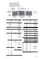
Overview PCS1.C62x
Übersicht PCS1.C62x
Récapitulatif PCS1.C62x
Block Pin Name I/O address Notes
X1 1
2
3
Data_Sbus
/Data_Sbus
GND
Port #3, RS-485
S-Bus
Standard Port
on all PCS1
X3 4 +5V
Port #2, RS-232
External display.
Standard port
on all
PCS1.Cx22 and
PCS1.Cx23
5 n.c.
6 GND
7 CTS2_ext
8 RxD2_ext
9 RTS2_ext
10 TxD2_ext
X2 1
2
3
4
Not used
Nicht verwendet
Non utilisé
X4 1 GND
Port #1
Optional port
RS-485/RS-422/
RS-232
2 I1A
3 I1B
4 I1C
5 I1D
6 I1G
X5 1 COM
3 E48 I 48 ch 0
I 48 ch 1
Inputs 0…10 V
or digital
Inputs 24 VDC
5 E49
7 GND
9 GND
11 GND
Base address = 48
see also FBox
PCS1.W2xx
13 GND
15 COM
17 COM
19 COM
21 COM
X5 2 COM
GND for Pt/Ni 1000
1
)
4 E64
I 64 ch 0
I 64 ch 1
I 64 ch 2
I 64 ch 3
I 64 ch 4
I 64 ch 5
6 E65
Pt/Ni 1000
8 E66
10 E67
12 GND
Base address = 64
see also FBox
PCS1.W3xx
14 GND
16 E68
18 E69
20 GND
22 GND
X6 1 E0 I 0 Digital
inputs, 8 ms
as PCD2.E110
3 E1 I 1
5 E2 I 2
7 E3 I 3
9 E4 I 4 Digital
inputs, 0.2 ms
as PCD2.E111
11 E5 I 5
13 GND
15 GND
17 GND
19 GND
21 GND
23 GND
24 GND
Block Pin Name I/O address Notes
X6 2 GND
Outputs 0…10 V
¹)
4 A80 O 80 ch 0
6 A81 O 80 ch 1
Base address = 80
see also FBox
PCS1.W4xx
8 A82 O 80 ch 2
10 A83 O 80 ch 3
12 GND
Selectable as
digital inputs
(as PCD2.B100)
(I 12 ... I 15) or as
digital outputs
(O 12 ... O 15)
14 +24V_EXT
16 E/A12 I/O 12
18 E/A13 I/O 13
20 E/A14 I/O 14
22 E/A15 I/O 15
(24) GND
X7 1 Uin +24VDC
Power supply
(inc. 24 VDC)
for relays
2 GND
3 GND
X8
1
NO20 O 20 1. Relay ²) /open
2
COM20 common
3
NC20 O 20 closed
4
NO21 O 21 2. Relay ²) /open
5
COM21 common
6
NC21 O 21 closed
7
NO22 O 22 3. Relay ²) /open
8
COM22 common
9
NC22 O 22 closed
10
NO23 O 23 4. Relay ²) /open
11 COM23 common
12 NC23 O 23 closed
X9
1
COM16 5. Relay ²) /common
2
NO16 O 16 open
3
COM17 6. Relay ²) /common
4
NO17 O 17 open
5
COM18 7. Relay ²) /common
6
NO18 O 18 open
7
COM19 8. Relay ²) /common
8
NO19 O 19 open
Intern A_M16 I 24 Switch pos.1
Intern A_M17 I 25
Intern A_M18 I 26
Intern A_M19 I 27
Intern A_M20 I 28
Acknowledgement
of manual/
Intern A_M21 I 29 emergency control
Intern A_M22 I 30 level
Intern A_M23 I 31 Auto/Man = 1/0
3
)
Intern A_M80_0 I 32 Switch pos.1
Intern A_M80_1 I 33
Intern A_M80_2 I 34
Intern A_M80_3 I 35
1
) extra filtered
2
) With manual/emergency control level as option
3
) Caution: If the manual/emergency control level is not equipped,
the status of inputs I24 to I35 is always logical “1”.
X9
X9
X5
X6
X7 X9
X8
X1 / X3
X2
X4
X5 1…2 digital inputs and/or
1…2 analogue inputs 0…10 V
6 analogue inputs Pt/Ni 1000 (12 Bit)
X6 6 digital inputs
4 analogue outputs 0…10 V
1…4 digital inputs and/or
1…4 digital outputs
X7
24 VDC
X9
4 relay outputs
(’make’ contact)
X8
4 relay outputs
(changeover)
X1 Port 3
RS-485 for S-Bus
or point-to-point
in MC mode
X3 Port 2
RS-232 for S-Bus,
external display or
point-to-point
X4 Port 1
Communications
PCD7.F1xxS at space A
as option
X2
Not used
Nicht verwendet
Non utilisé

Saia-Burgess Controls AG
Bahnhofstrasse 18
|
CH-3280 Murten
|
Switzerland
T 026 672 72 72
|
F 026 672 74 99
www.saia-pcd.com
|
Support www.sbc-support.com
|
www.saia-pcd.com
PCS1.C6xx
M4
(6)
204
195
150
78
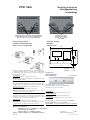
Dimension drawing
Massbild
Schémas cotés
Device depth: 60 mm
Gerätetiefe: 60 mm
Profondeur: 60 mm
PCS1.C62x Mounting instruction
Montageanleitung
Assemblage
Wall-mounting as option
Wandmontage als Option
Montage mural en option
(4’109’4849’0)
Standard mounting on 35 mm top-hat rail DIN EN 60715
Standard-Montage auf 35 mm-Hutschiene DIN EN 60715
Montage classique sur rail 35 mm DIN EN 60715
For more details, see Technical Information P+P26/345.
Weitere Informationen, siehe TI P+P26/345.
Pour tous détails, consulter l’information technique P+P26/345.
Mounting with the enclosed screws.
Befestigung mit den beiliegenden Schrauben.
Montage avec les visses fournies.
Terminal cover
Klemmenabdeckung
Capot cache-bornes 4’111’4927’0
Plug-in spring terminals
Steckbare Federkraftklemmen
Bornier à ressort embrochable
The process input terminals are up to 1.0 mm² and the proc-
ess output terminals are up to 1.5 mm². Process cable must
be bared along 7…8 mm (1.0 mm²) or 10 mm (1.5 mm²) and
inserted in the terminals.
UL Compliance:
For use of 60/75 °C copper (Cu) wire only.
IMPORTANT: Screwdrivers used should be type SDI 0.4 × 2.5 × 80
(max. width 2.5 mm).
Die Prozess-Eingangsklemmen sind bis 1.0 mm² und die
Prozess-Ausgangsklemmen bis 1.5 mm² ausgelegt. Die Pro-
zesskabel müssen 7…8 mm (1.0 mm²) bzw. 10 mm (1.5 mm²)
abisoliert und in die Klemmen gesteckt werden.
UL-konformer Einsatz:
Nur 60/75 °C Kupferleiter (Cu) verwenden.
WICHTIG: Schraubendreher des Typs SDI 0.4 × 2.5 × 80 ver-
wenden (max. Breite von 2.5 mm).
Leur section maximale est de 1 mm² pour les entrées et de
1.5 mm² pour les sorties. Le câble de raccordement côte
PCS doit être dénudé sur 7 à 8 mm (1 mm²) ou 10 mm
(1.5 mm²), puis être inséré dans les bornes.
Conformité UL :
N’utiliser que des fils de cuivre (Cu) 60/75 °C.
IMPORTANT: utiliser un tournevis du type SDI 0.4 × 2.5 × 80
(largeur max. 2.5 mm) pour ouvrir les ressorts.
UL Compliance:
Ambient temperature operation max. 55 °C
UL-konformer Einsatz:
Umgebungstemperatur Betrieb max. 55 °C
Conformité UL :
Température ambiante de service 55 °C maxi
4’319’5051’0 f 02.2014
Subject to change without notice

www.saia-pcd.com
PCS1.C6xx
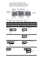
Communication Interfaces PCS1.C62x
Kommunikations-Schnittstellen PCS1.C6xx
Interfaces de communication PCS1.C6xx
Pins on terminal block X4 for PCD7.F1x0 communications modules at space A
Pin PCD7.F110S PCD7.F110S PCD7.F121S PCD7.F150S PCD7.F180S
RS-485 RS-422 RS-232 RS-485 *g.i. MP-Bus *g.i. = galvanically isolated
1 (gnd) GND GND GND — GND MP-Bus GND
2 (I1A) RX - TX TX TX RX - TX A-COM MP-Bus signal line
3 (I1B) /RX - /TX /TX RX /RX - /TX MST BELIMO
®
programming unit
4 (I1C) — RX RTS — IN BELIMO
®
programming unit detection
5 (I1D) — /RX CTS — GND BELIMO
®
programming unit GND
6 (I1G) — — — SGND —
1 2 3 4 5 6
GND
TX
/TX
RX
/RX
X4 (Port #1)
PCD7.F110S – RS-422
1 2 3 4 5 6
GND
+5 V DTR
TX
RX
RTS
CTS
X4 (Port #1)
1 2 3 4 5 6 7 8 9 10
X1 X3
PCD7.F121S – EIB/RS-232
1 2 3 4 5 6
GND
A-COM
MST
IN
GND
X4 (Port #1)
PCD7.F180S – BELIMO
®
MP-Bus
< 8 MFT/MFT2
(see 26/342)
Display PCD7.D230/RS-232 (C622 & C623)
1 2 3 4 5 6
GND
TX
RX
RTS
CTS
X4 (Port #1)
PCD7.F121S – RS-232
1 2 3 4 5 6
GND
RX-TX
/RX-/TX
X4 (Port #1)
1 2 3 4 5 6 7 8 9 10
X1 (Port #3)
X3
GND
/Data - S-Bus
Data - S-Bus
S-Bus/RS-485 PCD7.F110S – S-Bus/RS-485
X9
X9
X5
X6
X7 X9
X8
X1 / X3
X4
X5 1…2 digital inputs and/or
1…2 analogue inputs 0…10 V
6 analogue inputs Pt/Ni 1000 (12 Bit)
X6 6 digital inputs
4 analogue outputs 0…10 V
1…4 digital inputs and/or
1…4 digital outputs
X7
24 VDC
X9
4 relay outputs
(’make’ contact)
X8
4 relay outputs
(changeover)
X1 Port 3
RS-485 for S-Bus
or point-to-point
in MC mode
X3 Port 2
RS-232 for S-Bus,
external Display or
point-to-point
X4 Port 1
Communications
PCD7.F1xxS at space A
as option
GND
Plus +5V
TXD
RXD
/RTS
/CTS
X3 (Port #2)
X1
Minus –10V
1 2 3 4 5 6 7 8 9 10

www.saia-pcd.com
PCS1.C6xx
1 15
16
17
18
19
20
21
222
3
4
5
10
11
12
13
14
0…10 V
+ –
GND
6 8
7 9
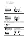
I/O Interfaces PCS1.C6xx
E/A-Schnittstellen PCS1.C6xx
Interfaces d’E/S PCS1.C6xx
X5
Details
24 VDC
COM = Ground
for all 12 bits
sensor inputs
Inputs
10 bits
X8
1
2
3
4
5
6
7
8
9 10
11
12
ON
MOC
CN
ON
MOC
CN
ON
MOC
CN
ON
MOC
CN
O 20
(4 A)
O 21
(4 A)
O 22
(2 A)
O 23
(2 A)
1 2 3 4 5 6 7 8
MO
C
ON
MO
C
ON
MO
C
ON
MO
C
ON
O 16
(2 A)
O 17
(2 A)
O 18
(4 A)
O 19
(4 A)
X9
1 21 2 3
12
Details
2-stage fan controller with mutual latching
2-stufige Ventilatorsteuerung mit gegenseitiger Verriegelung
Commande de ventilateur bivitesse avec verrouillage des sorties
entre elles.
X8 X9
220 VAC
Stage 2 Stage 1
X6
IMPORTANT If combined I/Os 12…15 are used as outputs, an external supply is required (24 VDC external). In such cases only source ope-
ration will be possible at the inputs.
WICHTIG Werden kombinierte E/A 12…15 als Ausgänge verwendet, ist eine externe Speisung erforderlich (24 VDC extern). In diesem
Fall ist bei den Eingängen nur Quellbetrieb möglich.
IMPORTANT Des qu’une des 4 I/O mixt 12…15 est utilisée comme sortie, une alimentation externe de 24 VCC est néssesaire à la borne 14.
Dans ce cas, seul le fonctionnement en logique positive est possible pour les autres entrées.
Details
1
2
3
4
5
12
13
14
15
16
17
18
19
GND
GND
+
–
0…10 V
Digital inputs in
source mode
Analogue
outputs
Digital
outputs
24 VDC
external
24 VDC
1 2 3
GND
GND
U
in.
+24 VDC
X7
Power supply
Speisung
Alimentation
1
2
3
4
5
6
7
8
9
10
11
12
13
14
15
16
17
18
19
20
21
22
COM
CH0
CH1
GND
GND
GND
GND
COM
COM
COM
COM
COM
CH0
CH1
CH2
CH3
GND
GND
CH4
CH5
GND
GND
Base-
address
48
Base-
address
64
{
0…10 V or
24 VDC
Pt/Ni 1000Pt/Ni 1000
{
{
1
2
3
4
5
6
7
8
9
10
11
12
13
14
15
16
17
18
19
20
21
22
23
I0
I1
I2
I3
I4
I5
GND
GND
GND
GND
GND
GND
GND
CH0
CH1
CH2
CH3
GND
I/O12
I/O13
I/O14
I/O15
GND
24
0…10 V
Base address 80
Digitale In-/
outputs
24 VDC ext.
{
{
Digital inputs 24 VDC
8 ms
0.2 ms
{
{
Pt/Ni 1000Pt/Ni 1000
-
 1
1
-
 2
2
-
 3
3
-
 4
4


SBC PCS1.C62x Mounting Instructions & Users Guide
- Taper
- Mounting Instructions & Users Guide
Documents connexes
-
SBC PCS1.C42x Mounting Instructions & Users Guide
-
-
-
-
-
-
-