MasterCraft 052-0060-2 Manuel utilisateur
- Catégorie
- Multimètres
- Taper
- Manuel utilisateur

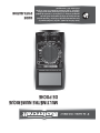
POCKET
DIGITAL MULTIMETER
INSTRUCTION
MANUAL
model no. 052-0060-2
Read and understand this instruction manual thoroughly
before using the product. It contains important
information for your safety as well as operating and
maintenance advice.
Keep this instruction manual for future use. Should this
product be passed on to a third party, then this
instruction manual must be included.


SAFETY INFORMATION
This meter has been designed according to IEC 61010 concerning
electronic measuring instruments with a measurement category
(CAT III 300V) and pollution degree 2.
2
WARNING
Do not use the meter if it is damaged. Before you use the meter,
inspect the case. Pay particular attention to the insulation
surrounding the connectors.
Inspect the test leads for damaged insulation or exposed metal.
Check the test leads for continuity. Replace damaged test leads
before you use the meter.
Do not use the meter if it operates abnormally.
Protection may be impaired. When in doubt, have the meter
serviced.
Do not operate the meter where explosive gas, vapour, or dust
is present.
Do not apply more than the rated voltage, as marked on the
meter, between terminals or between any terminal and earth
ground.
Before use, verify the meter's operation by measuring a known
voltage.
When measuring current, turn off circuit power before connect-
ing the meter in the circuit. Remember to place the meter in
series with the circuit.
To avoid possible electric shock or personal injury, follow these
guidelines:
WARNING

model no. 052-0060-2 | contact us 1-800-689-9928
3
WARNING
When servicing the meter, use only specified replacement
parts.
Use caution when working with voltage above 30 V RMS, 42 V
peak, or 60 V DC. Such voltages pose a shock hazard.
When using the probes, keep your fingers behind the finger
guards on the probes.
Connect the common test lead before you connect the live test
lead. When you disconnect test leads, disconnect the live test
lead first.
Remove the test leads from the meter before you open the
battery cover or the case.
Do not operate the meter with the battery cover or portions of
the case removed or loosened.
To avoid false readings, which could lead to possible electric
shock or personal injury, replace the battery as soon as the
battery indicator ( ) appears.
To avoid electrical shock, do not touch any conductor with hand
or skin.
Do not operate this instrument if your hand, a test lead or the
instrument is wet.
Remaining endangerment:
When an input terminal is connected to dangerous live potential
it is to be noted that this potential can occur at all other terminals!
CAT III -
Measurement Category III is for measurements performed in
building installation. Examples are measurements on distribution
boards, circuit breakers, wiring, including cables, bus-bars, junction
boxes, switches, socket-outlets in the fixed installation, and equipment
for industrial use and some other equipment, for example, stationary
motors with permanent connection to the fixed installation.
Do not use the meter for measurements within Measurement Categories
IV.

4
CAUTION
To avoid possible damage to the meter or to the equipment under
test, follow these guidelines:
Disconnect circuit power and discharge all capacitors before
testing resistance, diode, continuity and temperature.
Use the proper terminals, function and range for your measure-
ments.
Before measuring current, check the meter's fuses and turn off
the power to the circuit before connecting the meter to the
circuit.
Before rotating the range switch to change functions, disconnect
test leads from the circuit under test.
CAUTION

model no. 052-0060-2 | contact us 1-800-689-9928
5
INTRODUCTION
052-0060-2 multimeter is a compact 3 1/2-digit digital multimeter for
measuring DC and AC voltage, DC current, resistance, continuity,
diode, and battery.
It is easy to operate and is an ideal measurement tool.
Alternating current
Direct current
Both direct and alternating current
Caution, risk of electric shock.
Earth (ground) terminal
Fuse
Conforms to European Union directives
The equipment is protected throughout by double insulation or
reinforced insulation.
Caution, risk of danger. Refer to the operating manual before
use.
ELECTRICAL SYMBOLS
INTRODUCTION

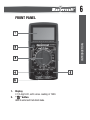
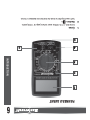
FRONT PANEL
1.
2.
Display
3 1/2-digit LCD, with a max. reading of 1999.
" " button
Used to enter/exit Data Hold mode.
6
INTRODUCTION

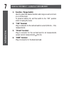
3. Function / Range Switch
Used to select the desired function and range as well as to turn
on or off the meter.
To preserve battery life, set this switch to the "OFF" position
when not using the meter.
6. "COM" Terminal
Plug-in connector for the black test lead.
4. "10A" Terminal
Plug-in connector for the red test lead for current (200 mA – 10 A)
measurements.
5. "VΩmA" Terminal
Plug-in connector for the red test lead for all measurements
except current measurements 200 mA.
7
INTRODUCTION
model no. 052-0060-2 | contact us 1-800-689-9928

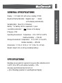
GENERAL SPECIFICATIONS
Display: 3 1/2-digit LCD, with a max. reading of 1999
Negative Polarity Indication: Negative sign " - " shown
on the display automatically
Sampling Rate: About 2 to 3 times/sec
Battery: 9 V battery, 6F22 or equivalent, 1 piece
Low Battery Indication: " " shown on the display
IP degree: IP20
Operating Environment: Temperature: 32 to 122ºF (0 to 50ºC)
Relative Humidity: < 75% RH
Storage Environment: Temperature: 14 to 140ºF (-10 to 60ºC)
Relative Humidity: < 85% RH
Dimensions: 5 7/16 x 2 15/16 x 1 1/4" (138 x 74 x 32 mm)
Weight: About 5 3/4 oz (163 g) (including battery)
SPECIFICATIONS
Readings are accurate for a period of one year after calibration at 64
to 82ºF (18 to 28ºC), with relative humidity < 75%.
Accuracy specifications take the form of:
± ([% of Reading]+[number of Least Significant Digits])
8
TECHNICAL SPECIFICATIONS

If the voltage being measured is > 300 V, the display may show
the value of the voltage, but the measurement is dangerous.
1
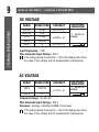
DC VOLTAGE
Input Impedance: 1 MΩ
Max. Allowable Input Voltage: 300 V
RANGE
OVERRANGE
INDICATION
"1" shown on
display
±(0.8% + 5)
±(0.5% + 5)
±(1.0% + 5)
±(1.2% + 5)
RESOLUTION ACCURACY
AC VOLTAGE
Frequency Range: 40–400 Hz
Max. Allowable Input Voltage: 300 V
Response: Average, calibrated in RMS of sine wave
RANGE
OVERRANGE
INDICATION
"1" shown on
display
200 V
100 mV
1 V
300 V
RESOLUTION ACCURACY
If the voltage being measured is > 300 V, the display may show
the value of the voltage, but the measurement is dangerous.
1
200 mV
2000 mV
20 V
200 V
300 V
100 μV
1 mV
10 mV
100 mV
1 V
model no. 052-0060-2 | contact us 1-800-689-9928
9
TECHNICAL SPECIFICATIONS

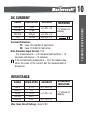
Fuse, 250 mA/300 V, Fast action
Fuse, 10 A/300 V, Fast action
(For measurements > 2 A: measurement duration < 10
seconds, and interval > 15 minutes)
If the current being measured is > 10 A, the display may
show the value of the current, but the measurement is
dangerous.
DC CURRENT
Overload Protection:
Max. Open Circuit Voltage: about 2.8 V
Max. Allowable Input Current: 10 A
RANGE
OVERRANGE
INDICATION
"1" shown on
display
2000 μA
10 mA
±(1.0% + 5)
±(1.2% + 5)
±(2.0% + 5)
10 A
200 mA
20 mA
RESOLUTION ACCURACY
1 μA
10 μA
100 μA
F1:
F2:
1
RESISTANCE
RANGE
OVERRANGE
INDICATION
"1" shown on
display
±(1.0% + 5)
±(1.2% + 5)
±(1.2% + 5)
RESOLUTION ACCURACY
200 Ω
2000 Ω
20 kΩ
200 kΩ
2000 kΩ
0.1 Ω
1 Ω
10 Ω
100 Ω
1 kΩ
10
TECHNICAL SPECIFICATIONS

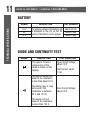
The working voltage of the battery will
be displayed on the LCD so that the
quality of the battery can be judged.
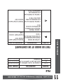
BATTERY
RANGE DESCRIPTION TEST CURRENT
1.5 V
9 V
12 V
about 20 mA
about 5 mA
about 4 mA
DIODE AND CONTINUITY TEST
RANGE DESCRIPTION TEST CONDITION
The approx. forward
voltage drop of the
diode is shown on the
display.
Open Circuit Voltage:
about 2.8 V
Test Current: about
1 mA
The built-in buzzer will
sound if the resistance
is less than about 30 Ω.
The buzzer may or may
not sound if the
resistance is between
30 Ω and 150 Ω.
The buzzer will not
sound if the resistance
is more than 150 Ω.
Open Circuit Voltage:
about 2.8 V
model no. 052-0060-2 | contact us 1-800-689-9928
11
TECHNICAL SPECIFICATIONS

OPERATING INSTRUCTIONS
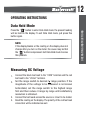
Press the " " button to enter Data Hold mode, the present reading
will be held on the display. To exit Data Hold mode, just press this
button again.
Data Hold Mode
Measuring DC Voltage
Connect the black test lead to the "COM" terminal and the red
test lead to the "VΩmA" terminal.
Set the range switch to desired range position. If the
magnitude of the voltage to be measured is not known
beforehand, set the range switch to the highest range
first and then reduce it range by range until satisfactory
resolution is obtained.
Connect the test leads across the source or circuit to be tested.
Read the reading on the display. The polarity of the red test lead
connection will be indicated as well.
1.
2.
3.
4.
12
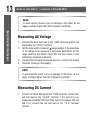
OPERATING INSTRUCTIONS
NOTE:
If the display blanks or the reading on the display does not
change after you turn on the meter, the cause may be that
the " " button is depressed. Exit Data Hold mode to solve
this problem.

NOTE:
NOTE:
To avoid electric shock to you or damage to the meter, do not
apply a voltage higher than 300 V between terminals.
Measuring DC Current
Connect the black test lead to the "COM" terminal. Connect the
red test lead to the "VΩmA" terminal if the current to be
measured is less than 200 mA. If the current is between 200 mA
and 10 A, connect the red test lead to the "10 A" terminal
instead.
1.
Measuring AC Voltage
Connect the black test lead to the "COM" terminal and the red
test lead to the "VΩmA" terminal.
Set the range switch to desired
range position. If the magnitude
of the voltage to be measured is not known beforehand, set the
range switch to the highest range first and then reduce it until
satisfactory resolution is obtained.
Connect the test leads across the source or circuit to be tested.
Read the reading on the display.
1.
2.
3.
4.
To avoid electric shock to you or damage to the meter, do not
apply a voltage higher than 300 V between terminals.
model no. 052-0060-2 | contact us 1-800-689-9928
13
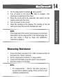
OPERATING INSTRUCTIONS

NOTE:
Set the range switch to desired range position.
Turn off power to the circuit you want to measure. Then
discharge all capacitors of the circuit.
Break the circuit path to be measured, and connect the test
leads in series with the circuit.
Turn on power to the circuit.
Read the reading on the display. The polarity of the red
test lead connection will be indicated as well.
2.
3.
4.
5.
6.
Measuring Resistance
Connect the black test lead to the "COM" terminal and the red
test lead to the "VΩmA" terminal.
Set the range switch to desired Ω range position.
Connect the test leads across the object to be measured.
Read the reading on the display.
1.
2.
3.
4.
For measurements > 1000 kΩ, the meter may take a
few seconds to stabilize reading. This is normal for high
resistance measurements.
1.
14
OPERATING INSTRUCTIONS
NOTE:
If the magnitude of the current to be measured is not known
beforehand, set the range switch to the highest range first
and then reduce it range by range until satisfactory
resolution is obtained.

NOTE:
When the input is not connected, i.e. at open circuit, "1" will
be displayed as an overrange indication.
Before measuring in-circuit resistance, disconnect all power
to the circuit to be tested and discharge all capacitors
thoroughly.
2.
3.
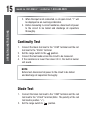
Continuity Test
Diode Test
Connect the black test lead to the "COM" terminal and the red
test lead to the "VΩmA" terminal.
Set the range switch to the position.
Connect the test leads across the circuit to be measured.
If the resistance is lower than about 30 Ω, the built-in buzzer
will sound.
Before test, disconnect all power to the circuit to be tested
and discharge all capacitors thoroughly.
Connect the black test lead to the "COM" terminal and the red
test lead to the "VΩmA" terminal (Note: The polarity of the red
test lead is positive "+").
Set the range switch to position.
1.
2.
3.
4.
1.
2.
model no. 052-0060-2 | contact us 1-800-689-9928
15
OPERATING INSTRUCTIONS

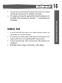
Battery Test
Connect the black test lead to the "COM" terminal and the red
test lead to the "VΩmA" terminal.
According to the rated voltage of the battery to be tested, set the
range switch to the corresponding BATT range position.
Connect the test leads to the two terminals of the battery to be
measured.
Read the working voltage of the battery on the display.
1.
2.
3.
4.
Connect the red test lead to the anode of the diode to be tested
and the black test lead to the cathode of the diode.
The display will show the approximate forward voltage drop of
the diode. If the connection is reversed, "1" will be shown on
the display.
3.
4.
16
OPERATING INSTRUCTIONS

Set the range switch to "OFF" position and remove all the test
leads from the meter.
Shake out any dirt which may exist in the terminals.
Soak a new swab with alcohol.
Work the swab around in each terminal.
MAINTENANCE
Except replacing fuse and battery, never attempt to repair or service
the meter.
Store the meter in a dry place when not in use. Don't store it in an
intense electromagnetic field environment.
Warning
Periodically wipe the case with a damp cloth and a little mild
detergent. Do not use abrasives or solvents.
Dirt or moisture in the terminals can affect readings. Clean the
terminals as follows:
General Maintenance
If the meter does not seem to work properly, check and replace
(as needed) the battery or fuses, or review this manual to verify
correct operation.
1.
2.
3.
4.
model no. 052-0060-2 | contact us 1-800-689-9928
17
MAINTENANCE

When the symbol " " appears on the display, it means that the
battery is low and must be replaced immediately.
To replace battery, remove the screw on the battery cover and
remove the battery cover. Replace the exhausted battery with a new
one of the same type. Reinstall the battery cover and the screw.
Fuse rarely needs to be replaced and is blown almost always as a
result of operator's error. To replace fuse, remove the screws on the
back cover and move the back cover aside gently. Replace the blown
fuse with a new one of the same ratings. Reinstall the back cover and
the screws.
BATTERY AND FUSE REPLACEMENT
This meter uses two fuses:
250 mA/300 V FAST fuse, Ø5×20mm
10 A/300 V FAST fuse, Ø5×20mm
F 1
F 2:
Manual: 1 piece
Test Lead: 1 pair
ACCESSORIES
18
MAINTENANCE

NOTE:
This Mastercraft product carries a one-year warranty against defects
in workmanship and materials. This product is not guaranteed
against wear, breakage or misuse.
WARRANTY
This manual is subject to change without notice.
Our company will not take any responsibility for any loss.
The contents of this manual can not be used as the reason
to use the meter for any special application.
1.
2.
3.
Dear Customer,
If you at some point intend to dispose of this article,
then please keep in mind that many of its components
consist of valuable materials, which can be recycled.
Please do not dispose of it in the garbage bin, but check
with your local council for recycling facilities in your
area.
DISPOSAL OF THIS ARTICLE
model no. 052-0060-2 | contact us 1-800-689-9928
19
WARRANTY
La page est en cours de chargement...
La page est en cours de chargement...
La page est en cours de chargement...
La page est en cours de chargement...
La page est en cours de chargement...
La page est en cours de chargement...
La page est en cours de chargement...
La page est en cours de chargement...
La page est en cours de chargement...
La page est en cours de chargement...
La page est en cours de chargement...
La page est en cours de chargement...
La page est en cours de chargement...
La page est en cours de chargement...
La page est en cours de chargement...
La page est en cours de chargement...
La page est en cours de chargement...
La page est en cours de chargement...
La page est en cours de chargement...
La page est en cours de chargement...
-
 1
1
-
 2
2
-
 3
3
-
 4
4
-
 5
5
-
 6
6
-
 7
7
-
 8
8
-
 9
9
-
 10
10
-
 11
11
-
 12
12
-
 13
13
-
 14
14
-
 15
15
-
 16
16
-
 17
17
-
 18
18
-
 19
19
-
 20
20
-
 21
21
-
 22
22
-
 23
23
-
 24
24
-
 25
25
-
 26
26
-
 27
27
-
 28
28
-
 29
29
-
 30
30
-
 31
31
-
 32
32
-
 33
33
-
 34
34
-
 35
35
-
 36
36
-
 37
37
-
 38
38
-
 39
39
-
 40
40


MasterCraft 052-0060-2 Manuel utilisateur
- Catégorie
- Multimètres
- Taper
- Manuel utilisateur
dans d''autres langues
- English: MasterCraft 052-0060-2 User manual
Documents connexes
Autres documents
-
Velleman DVM831 Fiche technique
-
Velleman DVM870 Manuel utilisateur
-
-
VOLTCRAFT VC-100 Operating Instructions Manual
-
VOLTCRAFT VC-125 Operating Instructions Manual
-
-
Velleman DVM601 Manuel utilisateur
-
Power Fist 8347676 Le manuel du propriétaire
-
Gardner Bender TK-5HCN Manuel utilisateur
-
Bosch Appliances 540H Manuel utilisateur