MasterCraft 2-Door Tall Cabinet Le manuel du propriétaire
- Taper
- Le manuel du propriétaire

continuation tabs
IMPORTANT:
Please read this manual carefully before assembling
and using this tall cabinet and save it for reference
INSTRUCTION
MANUAL
TALL CABINET
Model no. 068-0010-6

headline bars
continuation tabs
notes
warnings
headline bars
continuation tabs
notes
warnings
model no. 062-3582-8 | contact us 1-800-689-9928

TABLE OF CONTENTS
2
3
4
6
Safety
Parts List
Exploded View
Assembly Instructions
Warranty 13
NOTE:
If any parts are missing or damaged, or if you have any questions,
please call our toll-free helpline at 1-800-689-9928.
SAVE THESE INSTRUCTIONS
This manual contains important safety and operating instructions.
Read all instructions and follow them with use of this product.
1
TABLE OF CONTENTS

SAVE THESE INSTRUCTIONS
This manual contains important safety and operating instructions.
Read all instructions and follow them with use of this product.
2
headline bars
continuation tabs
notes
warnings
headline bars
continuation tabs
notes
warnings
model no. 068-0010-6 | contact us 1-800-689-9928
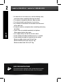
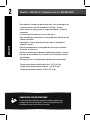
• To reduce the risk of serious injury, read the following safety
instructions before assembling and using the cabinet.
• This cabinet is intended for domestic, indoor use only.
• The cabinet should be positioned on a level surface.
• Any assembly or maintenance of the cabinet must be carried
out by adults only.
• Arrange for necessary manpower when assembling and moving
the cabinet.
• Check all the nuts and bolts periodically for tightness.
When required, tighten them again.
• Use a slightly damp, soft cloth to clean the cabinet.
• Do not stand on the cabinet and do not use it as a scaffold.
• Do not exceed the weight limit specified for this cabinet.
Maximum middle shelves load: 100 lb (45 kg).
Maximum bottom panel load: 200 lb (91 kg).
Maximum cabinet load: 500 lb (227.3kg).
SAFETY
headline bars
continuation tabs
notes
warnings
headline bars
continuation tabs
notes
warnings
model no. 062-3582-8 | contact us 1-800-689-9928

3
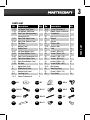
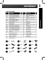
PARTS LIST
No.
1-A1
1-A2
1-A3
2-A1
2-A2
3
4
5
6-A1
6-A2
6-A3
7-A1
7-A2
7-A3
8
9
10
6-1
15-2
No.
16-2
17-2
21
22
23
25
27
27-B
34
41
42
52
53
54
55
55-A
60
61
63
Description
Corner Protection-B
Middle Corner Protection
Screwdriver
Key
(attached at the door handle)
Magnet
Wrench
Washer (M4)
Washer (M8)
Hook
Screw F (M4 x 8L)
Screw G (M4 x 30L)
Screw K (M5 x 10L)
Screw L (M4 x 6L)
Screw N (M4 x 10L)
Screw M (M6 x 50L)
Wall Anchor
Mounting Strap
Screw O (M4 x 12L)
Press Knob
Description
Left Upper Side Panel
Left Bottom Side Panel
Side Panel Reinforcement
Connection Part
Right Side-Upper Panel
Right Side-Bottom Panel
Top Panel
Bottom Panel
Middle Shelf
Left Door-Upper Panel
Left Door-Bottom Panel
Door Panel Connection Part
Right Door-Upper Panel
Right Door-Bottom Panel
Key Rod
Upper Back Panel
Middle Back Panel
Bottom Back Panel
Levelling Feet
Corner Protection-A
Qty.
1
1
2
1
1
1
1
3
1
1
2
1
1
1
1
2
1
4
2
Qty.
2
2
1
2
2
1
2
2
12
54
12
8
1
28
2
2
2
2
25
PARTS LIST
41 M4x8
27
M4 27-B M8
60
42
M4x30 52 M5x10
53
M4x6
54
M4x10 55 M6x50
55-A
M6
61 M4x12 63

headline bars
continuation tabs
notes
warnings
headline bars
continuation tabs
notes
warnings
model no. 062-3582-8 | contact us 1-800-689-9928
4
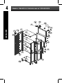
EXPLODED VIEW
headline bars
continuation tabs
notes
warnings
headline bars
continuation tabs
notes
warnings
model no. 068-0010-6 | contact us 1-800-689-9928
#63

5
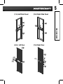
EXPLODED VIEW
(1-A) Left Side Panel (2-A) Right Side Panel
(6-A) Left Door (7-A) Right Door
#52
#41
#53

headline bars
continuation tabs
notes
warnings
headline bars
continuation tabs
notes
warnings
model no. 062-3582-8 | contact us 1-800-689-9928
6
ASSEMBLY INSTRUCTIONS
headline bars
continuation tabs
notes
warnings
headline bars
continuation tabs
notes
warnings
model no. 068-0010-6 | contact us 1-800-689-9928
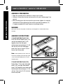
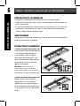
ASSEMBLY PREPARATION
• Begin the assembly of this cabinet on a clean, level surface.
• Remove all items from the box and ensure that all parts listed on page 3 are
present.
• When installing parts that have more than one screw, tighten all screws by
hand before finishing tightening them with the provided screwdriver (21).
If a power screwdriver is used, keep on a low torque setting.
WARNING
Some parts may have sharp edges. To avoid injury, wearing gloves is recommended during
assembly.
ASSEMBLY INSTRUCTIONS
1. Install Left Side Panel (1-A)
Place the left side-upper panel (1-A1)
and left side-bottom panel (1-A2)
together. Insert the side panel
reinforcement connection part (1-A3)
into the slot of the left side-upper
panel. Use 3 pcs of screw G (42) to
secure from the top side.
Note: Before tightening screws, make sure
the corners and edges of left side-upper panel
(1-A1) and left side-bottom panel (1-A2) are
completely flush.
2. Install Left Side Panel (2-A)
Repeat Step 1. Place right side-upper
panel (2-A1) and right side-bottom
panel (2-A2) together. Insert side panel
reinforcement connection part (1-A3),
and use 3 pcs screw G (42) to secure
from the top side.
#1
-A3
#1-A3
#42
#2-A1
#2-A2
#2-A3

7
ASSEMBLY INSTRUCTIONS
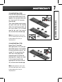
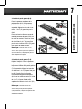
3. Install Left Door (6-A).
Place left door-upper panel (6-A1)
and left door-bottom panel (6-A2)
together. Line up screw holes and
use 1 pc screw F (41) to secure
from the side.
Then, place the door panel connec-
tion part (6-A3) over the touching
sides. Line up the screw holes and
use 4 pcs screw F (41) to secure
from the top, and 4 pcs screw K
(52) to secure from outside edge.
Note: Before tightening screws, make
sure the left door-upper panel (6-A1) and
left door-bottom panel (6-A2) are
completely flush.
4. Install Left Door (7-A).
Repeat Step 3. Place right
door-upper panel (7-A1) and right
door-bottom panel (7-A2) together.
Line up screw holes and use 1 pc
screw F (41) to secure from the
side. Then, attach door panel
connection part (6-A3) over the
touching sides, using 4 pcs screw
F (41) to secure from the top
touching side and 4 pcs screw K
(52) to secure from outside edge.
Note: Before tightening screws, make
sure the left door-upper panel (7-A1) and
left door-bottom panel (7-A2) are
completely flush.

headline bars
continuation tabs
notes
warnings
headline bars
continuation tabs
notes
warnings
model no. 062-3582-8 | contact us 1-800-689-9928
8
headline bars
continuation tabs
notes
warnings
headline bars
continuation tabs
notes
warnings
model no. 068-0010-6 | contact us 1-800-689-9928
Front
Front
Back
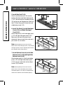
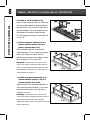
5. Install Key Rod (7-A3)
Attach and insert key rod (7-A3) into the
bottom tab hole of right door-bottom panel
(7-A2). Twist out the pre-assembled screw L
(53) on the key rod linkage plate. Attach key
rod (7-A3) by lining up the screw hole and
retightening screw L (53).
6. Install Top Panel (3) to Left Side Upper
Panel (1-A1) and Right Side Upper
Panel (2-A1)
Attach top panel (3) to left side upper panel
(1-A1) and right side upper panel (2-A1).
Make sure the front of the panel faces
downward. Line up screw holes, and use 6
pcs screw F (41) to secure.
Note: Before tightening screws, make sure the
bottom corners of left side upper panel (1-A1) and right
side upper panels (2-A1) are completely flush with the
back and front corners of top panel (3).
7. Install Bottom Panel (4) to Left Side
Bottom Panel (1-A2) and Right Side
Bottom Panel (2-A2)
Attach bottom panel (4) to left side-bottom
panel (1-A2) and right side-bottom panel
(2-A2). Line up screw holes and use 6 pcs
screw G (42) to secure.
Note: Before tightening screws, make sure the
bottom corners of left side-bottom panel and right
side-bottom panels (1-A2, 2-A2) are completely flush
with the back and front corners of bottom panel (4).
ASSEMBLY INSTRUCTIONS

9
ASSEMBLY INSTRUCTIONS
#21
#63
#6-1
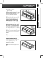
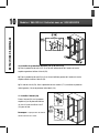
8. Install Back Panels
(8, 9 and 10)
1) Attach bottom back panel (10 ) onto
both left and right side panels (1-A2
and 2-A2) and bottom panel (4).
2) Attach both middle back panels (9)
above bottom back panel (10) the
same way. Place the groove of the
middle back panel (9) onto the top
edge of the bottom back panel (10).
3) Line up all the screw holes. use 24
pcs screw F (41) to secure each back
panel’s four sides to back of cabinet
left and right side panels (1-A and 2-A).
4) Using 13 pcs press knob (63), press
into the other holes to attach all back
panels.
Note: Do not fully tighten screw F (41) before
the press knobs (63) are secured.
9. Install Levelling Feet (6-1)
Install levelling feet (6-1) into the four
corners of bottom panel (4). Use
wrench (25) to tighten.
Note: Rotate/stand cabinet upright after this
step.

headline bars
continuation tabs
notes
warnings
headline bars
continuation tabs
notes
warnings
model no. 062-3582-8 | contact us 1-800-689-9928
10
headline bars
continuation tabs
notes
warnings
headline bars
continuation tabs
notes
warnings
model no. 068-0010-6 | contact us 1-800-689-9928
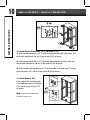
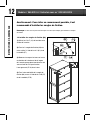
10. Install Corner Protections (15-2, 16-2 and 17-2)
1) Attach corner protection A (15-2) onto the cabinet bottom right side corner and
the top left side corner, and use 10 pcs screw N (54) to secure.
2) Attach corner protection B (16-2) onto the cabinet bottom left side corner and
the top right side corner, and use 10 pcs screw N (54) to secure.
3) Attach middle corner protection (17-2) to the middle of left side panel (1-A) and
right side panel (2-A), and use 8 pcs screw N (54) to secure.
11. Install Magnet (23)
Place magnet (23) onto top panel
(3) and bottom panel (4) facing the
front, and use 4 pcs screw F (41)
to secure.
Note: The black plate of the magnet
should be facing the front.
ASSEMBLY INSTRUCTIONS

11
12. Install Middle Shelves (5)
1) Choose the desired height for each
middle shelf (5) inside cabinet. Place
the hooks (34) into the four side hook
slots of the cabinet body, and make
sure they are at the same height.
2) Place each middle shelf (5) into the
cabinet, and push it down onto the
hooks (34).
13. Install Left and Right Doors
(6-A and 7-A)
1) Attach left door (6-A) to left side
panel (1-A), and use 5 pcs screw F
(41) to secure. Use 6 pcs press knob
(63), 1 pc of screw F (41) at the top
side, 3 pcs of screw F (41) in the
middle, and 1 pc of screw F (41) at the
bottom. Press 6 pcs press knob (63)
into the other holes to further secure
the door panels.
Note: The screw holes on the door hinge have
tolerance, enabling the door to be adjusted and
centred in the door frame. Place top, middle and
bottom screws first. Don't tighten screws
completely — this may save time by avoiding
having to make slight adjustments for levelling
door panels later.
2) Install right door (7-A) the same
way.
#41
#63
ASSEMBLY INSTRUCTIONS

12
headline bars
continuation tabs
notes
warnings
headline bars
continuation tabs
notes
warnings
model no. 068-0010-6 | contact us 1-800-689-9928
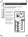
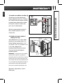
Warning: To prevent possible tipping, it is suggested that
the mounting straps be installed.
Note: A power drill and bit (not included) are necessary to install the mounting straps.
14. Install Mounting Strap (60)
1) Remove 2 pcs screw F (41) from the
top of cabinet back corners.
2) Attach 2 pcs mounting strap (60) to
the back corners, using screw O (61)
and washer (27) to secure.
3) Measure and mark holes on the wall
according to the cabinet height and
width, drill two holes in the wall with a
5/16" drill bit, and insert the wall
anchor (55-A) into the hole.
4) Attach the other end of the
mounting strap (60) to the wall using
screw M (55) and washer (27-B).
ASSEMBLY INSTRUCTIONS
headline bars
continuation tabs
notes
warnings
headline bars
continuation tabs
notes
warnings
model no. 062-3582-8 | contact us 1-800-689-9928

13
This Mastercraft® product carries a one (1) year warranty from the date of the original
retail purchase, against defects in material and workmanship. Subject to the condi-
tions and limitations described below, this product, if returned to us with proof of
purchase within the stated warranty period and if covered under this warranty, will be
repaired or replaced (with the same model, or one of equal value or specification), at
our discretion. We will bear the cost of any repair or replacement and any costs of
labour relating thereto.
These warranties are subject to the following conditions and limitations:
a. a bill of sale verifying the purchase and purchase date must be provided
b. this warranty will not apply to any product or part thereof which is worn or broken
or which has become inoperative due to abuse, misuse, accidental damage, neglect or
lack of proper installation, operation or maintenance (as outlined in the applicable
owner's manual or operating instructions) or which is being used for industrial, profes-
sional, commercial or rental purposes;
c. this warranty will not apply to normal wear and tear or to expendable parts or acces-
sories that may be supplied with the product which are expected to become inopera-
tive or unusable after a reasonable period of use;
d. this warranty will not apply to routine maintenance and consumable items such as,
but not limited to, fuel, lubricants, vacuum bags, blades, belts, sandpaper, bits, fluids,
tune-ups or adjustments;
e. this warranty will not apply where damage is caused by repairs made or attempted
by others (i.e., persons not authorized by the manufacturer);
f. this warranty will not apply to any product that was sold to the original purchaser as
a reconditioned or refurbished product (unless otherwise specified in writing);
g. this warranty will not apply to any product or part thereof if any part from another
manufacturer is installed therein or any repairs or alterations have been made or
attempted by unauthorized persons;
h. this warranty will not apply to normal deterioration of the exterior finish, such as, but
not limited to, scratches, dents, paint chips, or to any corrosion or discolouring by heat,
abrasive and chemical cleaners; and
i. this warranty will not apply to component parts sold by and identified as the product
of another compay, which shall be covered under the product manufacturer's warran-
ty, if any.
WARRANTY

headline bars
continuation tabs
notes
warnings
Additional Limitations
This warranty applies only to the original purchaser and may not be
transferred. Neither the retailer not the manufacturer shall be liable for
any other expense, loss or damage, including, without limitation, any
indirect, incidental, consequential or exemplary damages arising in
connection with the sale, use or inability to use this product.
Notice to Consumer
This warranty gives you specific legal rights, and you may have other
rights, which may vary from province to province. The provisions
contained in this warranty are not intended to limit, modify, take away
from, disclaim or exclude any statutory warranties set forth in any applica-
ble provincial or federal legislation.
Made in China
Imported by
Mastercraft Canada Toronto, Canada M4S 2B8

continuation tabs
IMPORTANT :
Veuillez lire attentivement ce guide avant d’assembler
et d’utiliser cette armoire haute et le conserver à titre de référence.
GUIDE
D’UTILISATION
ARMOIRE HAUTE
Modèle nº 068-0010-6

headline bars
continuation tabs
notes
warnings
headline bars
continuation tabs
notes
warnings
model no. 062-3582-8 | contact us 1-800-689-9928

TABLE DES MATIÈRES
2
3
4
6
Sécurité
Liste des pièces
Vue éclatée
Instructions d’assemblage
Garantie
13
REMARQUE :
Si des pièces sont manquantes ou endommagées, ou si vous avez des questions,
veuillez contacter notre service de soutien téléphonique sans frais au 1 800 689-9928.
CONSERVEZ CES INSTRUCTIONS
Le présent guide d’utilisation contient un mode d’emploi et des
consignes de sécurité importants. Lisez et respectez toutes les
instructions lorsque vous utilisez cet article.
1
TABLE DES MATIÈRES

CONSERVEZ CES INSTRUCTIONS
Le présent guide d’utilisation contient un mode d’emploi et des
consignes de sécurité importants. Lisez et respectez toutes les
instructions lorsque vous utilisez cet article.
2
headline bars
continuation tabs
notes
warnings
headline bars
continuation tabs
notes
warnings
Modèle n° 068-0010-6 | Contactez-nous au 1 800 689-9928
• Pour réduire les risques de blessures graves, lisez les consignes de
sécurité suivantes avant d’assembler et d’utiliser l’armoire.
• Cette armoire est conçue pour un usage domestique, à l’intérieur
seulement.
• L’armoire doit être placée sur une surface plane.
• Tout assemblage ou entretien de l’armoire doit être effectué par des
adultes seulement.
• Demandez à d’autres personnes de vous aider à assembler et
déplacer l'armoire.
• Vérifiez périodiquement le serrage de tous les écrous et boulons.
Au besoin, resserrez-les.
• Utilisez un chiffon doux légèrement humide pour nettoyer l’armoire.
• Ne vous tenez pas debout sur l’armoire et ne l’utilisez pas comme
échafaudage.
• Ne dépassez pas la limite de poids spécifiée pour cette armoire.
Charge maximale des tablettes du milieu : 100 lb (45 kg).
Charge maximale du panneau inférieur : 200 lb (91 kg).
Charge maximale de l’armoire : 500 lb (227.3 kg).
SÉCURITÉ
headline bars
continuation tabs
notes
warnings
headline bars
continuation tabs
notes
warnings
model no. 062-3582-8 | contact us 1-800-689-9928
La page est en cours de chargement...
La page est en cours de chargement...
La page est en cours de chargement...
La page est en cours de chargement...
La page est en cours de chargement...
La page est en cours de chargement...
La page est en cours de chargement...
La page est en cours de chargement...
La page est en cours de chargement...
La page est en cours de chargement...
La page est en cours de chargement...
La page est en cours de chargement...
-
 1
1
-
 2
2
-
 3
3
-
 4
4
-
 5
5
-
 6
6
-
 7
7
-
 8
8
-
 9
9
-
 10
10
-
 11
11
-
 12
12
-
 13
13
-
 14
14
-
 15
15
-
 16
16
-
 17
17
-
 18
18
-
 19
19
-
 20
20
-
 21
21
-
 22
22
-
 23
23
-
 24
24
-
 25
25
-
 26
26
-
 27
27
-
 28
28
-
 29
29
-
 30
30
-
 31
31
-
 32
32


MasterCraft 2-Door Tall Cabinet Le manuel du propriétaire
- Taper
- Le manuel du propriétaire
dans d''autres langues
Documents connexes
Autres documents
-
 Canadian Tire Branded MotoMaster 400 Lumen Flexible USB Rechargeable LED Worklight Le manuel du propriétaire
-
Kohler K-9928-0 Guide d'installation
-
Schumacher Motomaster 011-1962-8 – CT051 Simple Series Onboard Battery Charger Le manuel du propriétaire
-
 Champion Power Equipment 055-0216-8-100687 Manuel de l’opérateur
-
-
-
-

