MasterCraft 3-Gallon Electric Le manuel du propriétaire
- Catégorie
- Compresseurs d'air
- Taper
- Le manuel du propriétaire

headline bars
tion tabs
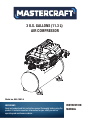
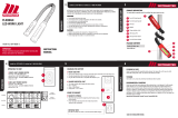
INSTRUCTION
MANUAL
IMPORTANT:
Read and understand this instruction manual thoroughly before using the
product. It contains important information for your safety as well as
operating and maintenance advice.
3 U.S. GALLONS (11.3 L)
AIR COMPRESSOR
Model no. 058-1892-4

headline bars
continuation tabs
notes
warnings
3
T
NOTE:
If any parts are missing or damaged, or if you have any questions, please call our toll-free helpline
at 1-800-689-9928.
SAVE THESE INSTRUCTIONS
Keep this instruction manual for future use. Should this product be passed on to a third party,
then this instruction manual must be included.
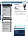
TABLE OF CONTENTS
TECHNICAL SPECIFICATIONS 4
SAFETY GUIDELINES 5
KEY PARTS DIAGRAM 8
KEY PARTS LIST 9
INTENDED USE 10
ASSEMBLY 12
OPERATING INSTRUCTIONS 14
MAINTENANCE 18
TROUBLESHOOTING 20
EXPLODED VIEW 22
PARTS LIST 23
WARRANTY 24
headline bars
continuation tabs
notes
warnings
TABLE OF CONTENTS

headline bars
continuation tabs
notes
warnings
headline bars
continuation tabs
notes
warnings
headline bars
continuation tabs
notes
warnings
headline bars
continuation tabs
notes
warnings
headline bars
continuation tabs
notes
warnings
4 5
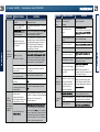
TECHNICAL SPECIFICATIONS
SAFETY GUIDELINES
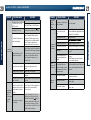
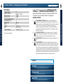
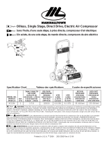
TECHNICAL SPECIFICATIONS
*CFM: Cubic feet per minute.
1.5
3.0
135
105
3 U.S. GALLONS (11.3 L)
OIL-LESS
UMC
120 V, 60 Hz, 12 A
24 lb 11 oz (11.2 kg)
SJT 16 AWG/72" (1.83 m)
2.2
RUNNING HP
TANK SIZE
AIR DELIVERY (CFM*) @ 40 PSI
AIR DELIVERY (CFM*) @ 90 PSI
MAXIMUM PRESSURE (PSI)
PUMP DESIGN
MOTOR
POWER
WEIGHT
POWER CORD
This manual contains information that relates to PROTECTING PERSONAL SAFETY
and PREVENTING EQUIPMENT PROBLEMS.
carefully and understand it thoroughly before using the product. The symbols listed
below are used to indicate this information.
IMPORTANT!
Installation, operation or maintenance information that is important but not hazard related.
It is very important to read this manual
CAUTION!
Potential hazard that may result in moderate injury or damage to equipment.
WARNING!
Potential hazard that could result in serious injury or loss of life.
DANGER!
Potential hazard that will result in serious injury or loss of life.
Safety Advice
model no. 058-1892-4 | contact us 1-800-689-9928
CUT-IN PRESSURE (PSI)
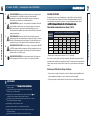
1.
RISK OF FIRE OR EXPLOSION.
2.
RISK OF ELECTRIC SHOCK. Do not expose to rain. Store indoors. Hazardous voltage.
Disconnect from power source before servicing. Compressor must be grounded. Do not
use grounding adaptors.
3.
K
4. RISK OF BURSTING.
Check the maximum pressure rating in the manual or identification
5. Do not adjust the pressure switch or safety valve for any reason. They
RISK OF BURSTING.
Do not spray a flammable or combustible liquid or paint
pilot lights or in a confined area. The spray area must be well-ventilated.
Keep compressor at least 20' (6 m) away from spray area. Do not carry and operate the
compressor or any other electrical device near the spray area. Never smoke when spraying.
Use a minimum of 25' (7.6 m) of hose to connect a spray gun to the compressor.
near sparks, flames,
RIS OF PERSONAL INJURY. Never spray compressed air or material at self or others.
.
label. The compressor outlet pressure must be regulated so that it does not exceed the
maximum pressure rating. Relieve all pressure in the hose before removing or attaching
accessories. Make sure the regulator is adjusted so that the compressor outlet pressure is
set lower than the maximum operating pressure of the spray gun or tool. Before starting the
compressor, pull the ring on the safety valve to make sure the valve moves freely (see diagram
on page 19). Drain water from tank after each use. Do not weld or repair tank.
have been preset at the factory for this compressor’s maximum pressure. Tampering
with the pressure switch or the safety valve
may cause personal injury or property damage.

headline bars
continuation tabs
notes
warnings
headline bars
continuation tabs
notes
warnings
6 7
model no. 058-1892-4 | contact us 1-800-689-9928
SAFETY GUIDELINES
SPECIFIC SAFETY GUIDELINES FOR THE SLIDING WET TILE SAW
SAFETY GUIDELINES
6. RISK OF BURNS. The pump and the manifold generate high temperatures. In order to
avoid burns or other injuries, do not touch the pump, the manifold or the transfer tube
while the compressor is running. Allow the parts to cool down before handling or
servicing. Keep children away from the compressor at all the times.
7.
Be certain to read all labels when you are spraying paints or
toxic materials, and follow all safety instructions. Use a respirator mask if there is a
chance of inhaling anything you are spraying. Also, NEVER directly inhale the air
produced by a compressor.
8. Wear ANSI Z87.1 or CSA Z94.3 approved safety goggles when
using an air compressor. Do not point any nozzle or sprayer toward a person or any
part of the body. Serious injury may occur if the spray penetrates the skin.
BREATHING RISK.
RISK OF EYE INJURY.
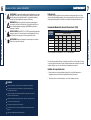
Recommended Minimum Wire Gauge for Extension Cords* (120 V)
* Based on limiting the line voltage drop to 5 V at 150% of the rated amperes.
The smaller the gauge number of the wire, the greater the capacity of the cord. For example, a 14-gauge
cord can carry a higher current than a 16-gauge cord. When using more than one extension cord to make
up the total length, be sure each cord contains at least the minimum wire size required.
Guidelines for using extension cords
•
•
Ensure your extension cord is properly wired and in good electrical condition. Always replace a
damaged extension cord or have it repaired by a qualified technician before using it.
Protect your extension cords from sharp objects, excess heat, and damp or wet areas.
WARNING!
Pull the pressure safety valve ring every day in order to ensure that the valve is functioning properly.
The compressor must be located in a well-ventilated area for cooling and must be a minimum of 12"
(31 cm) away from the nearest wall.
Protect the air hose and the power cord from damage and puncture. Inspect them for weak or worn spots
every week, and replace them if necessary.
Always wear hearing protection when using an air compressor. Failure to do so may result in hearing loss.
Do not carry the compressor while it is running.
Do not operate the compressor if it is not in a stable position.
Do not operate the compressor on a rooftop or an elevated position that could allow the unit to fall or be
tipped over.
Always replace a damaged gauge before operating the unit again.
Extension cords
As the distance from the supply outlet increases, you must use a heavier gauge extension cord. Using
extension cords with inadequately sized wire causes a serious drop in voltage, resulting in loss of power
and possible product damage. Refer to the table here to determine the required minimum wire size.
9. RISK TO HEARING. Always wear hearing protection when using an air compressor.
Failure to do so may result in hearing loss.
CORD SIZE IN AWG (AMERICAN WIRE GAUGE)
Extension cord length
25' (7.6 m) 50' (15 m) 75' (23 m) 100' (30 m) 150' (46 m) 200' (60 m)
0 – 5 16 16 16 14 12
5.1 – 8 16 16 14 12 —
8.1 – 12 14 14 12 10 —
12.1 – 15 12 12 10 10 —
15.1 – 20 10 10 10 —
12
10
—
—
— —
AMPERE
RATING

headline bars
continuation tabs
notes
warnings
headline bars
continuation tabs
notes
warnings
8 9
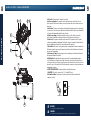
KEY PARTS DIAGRAM
KEY PARTS LIST
WARNING!
Do not exceed the tool’s maximum working pressure.
WARNING!
Do not attempt to open the drain valve when there is more than 10 PSI of air pressure in the tank.
Plug
Grounding pin
Grounded
outlets
model no. | contact us 1-800-689-9928058-1892-4
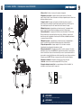
B. Air Pressure Regulator: The regulator is used to adjust the pressure inside the line to the tool
that is being used. Turn the knob clockwise to increase the pressure and counter-clockwise to decrease
the pressure
C. Safety Valve: This valve is used to prevent system failure by draining pressure from the system when
it reaches a preset level if the pressure switch has not shut down the motor. It will pop open automatically,
or it can be activated manually by pulling the ring on the valve.
D. Tank Pressure Gauge: The gauge measures the pressure level of the air that is stored in the
tank. It cannot be adjusted by the operator and it does not indicate the pressure inside the line.
E. Power Cord: This compressor should be used on a nominal 120 V grounded circuit. Use a power
cord that is equipped with a grounding plug. Verify that the compressor is plugged into an outlet that has
the same conguration as the plug. Do not use an adaptor with this compressor.
F. Electric Motor: The motor is used to power the pump. It is equipped with a thermal overload protector.
If the motor overheats for any reason, the thermal overload protector will shut it down in order to prevent
the motor from being damaged.
I. OUTLET PRESSURE GAUGE: The gauge measures the regulated outlet pressure.
H. On/Off Switch: This switch turns the compressor on and off. It is operated manually and when
it is in the ON position, it allows the motor to start if the pressure in the air tank is below the factory set
cut-in pressure and causes the motor to stop if the pressure in the air tank reaches the factory set cut-out
pressure. Be sure to set this switch to the OFF position when the compressor is not being used and before
unplugging the compressor.
J. AIR OUTLET: The outlet is connected to the 1/4” (6.4 mm) NPT air hose.
K. Air Tank Drain Valve: The drain valve is used to remove moisture from the air tank after the
compressor is shut off.
G. Air Compressor Pump: The pump compresses the air and discharges it into the tank via the piston
that moves up and down in the cylinder.
F
G
K
B
HE
J
C
A
D
I
A. Air Tank: The tank is where the compressed air is stored.

headline bars
continuation tabs
notes
warnings
headline bars
continuation tabs
notes
warnings
10 11
INTENDED USE
INTENDED USE
WARNING!
This air compressor is not designed for continuous operation or unlimited commercial operations
and must be used in dry areas only. This air compressor is intended to be used in maximum
30-minute intervals and should rest for 30 minutes before used again. Do not exceed the
maximum working time.
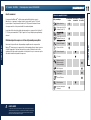
Air Tool
Tool Compatibility Chart
Operates Tool
Continously
Not
Recommended
Operates Tool
Intermittently
Finishing Nailer (16 gauge)
Framing Nailer
Flooring Nailer
Die Grinder/Angle
Grinder/Air Ratchet
Cut-Off Tools
DIY Paint Sprayers
Brad Nailer (18 gauge)
3-in-1 Brad/Finishing/Stapler
Impact Wrench
Drill/Hammer/Chisel/Shears
Sander/Polisher
Grease/Caulking Gun
Before you start
This Mastercraft® Air Compressor is ideal for a wide range of applications, from fastening to greasing and
engine cleaning. The 3-gallon (11.3 L) design provides optimum pressure. It features a 1.5 HP induction
motor for quiet operation and a cast-iron, oil-free pump for long-lasting, reliable performance.
The procedures described in this manual are solely for this 3-gallon (11.3 L) air compressor at a maximum
of P=135 PSI. The device has been designed/constructed for household use only.
Compatible compressor and air tool: proper usage and operation
Always ensure the use of appropriately matched air tools with your Mastercraft® Air Compressor. Be sure
that the air compressor being used can supply the appropriate volume, pressure and delivery rate of air to
the tool(s) without running continuously. Using tools or combinations of tools that, together or separately,
require more than the air compressor can deliver will void the air compressor guarantee/warranty .
model no. 058-1892-4 | contact us 1-800-689-9928

headline bars
continuation tabs
notes
warnings
headline bars
continuation tabs
notes
warnings
12 13
ASSEMBLY
ASSEMBLY
Assembly
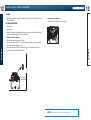
1. Unpack the air compressor unit. Inspect the unit for damage. If the unit has been damaged, contact the
retailer immediately.
THE CARTON SHOULD CONTAIN:
• Air compressor
• Owner’s manual
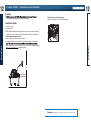
12" (31 cm)
2. Check the air compressor’s identification label to ensure that you have purchased the intended model
and that it has the required pressure rating for its intended use.
3. Positioning of the air compressor:
• Position the air compressor near an electrical outlet.
• The compressor must be at least 12" (31 cm) from any wall or obstruction, in a clean, well-ventilated
area to ensure sufficient airflow and cooling.
• Place the air compressor on the floor or a hard, level surface. The air compressor must be level to
ensure proper drainage of the moisture in the tank.
4. Connect air hose to compressor
• Connect the air hose to the compressor’s air outlet (J).
NOTE: ¼" (6.4 mm) NPT air hose is required for connecting to the air compressor.
Wall
model no. 058-1892-4 | contact us 1-800-689-9928

headline bars
continuation tabs
notes
warnings
headline bars
continuation tabs
notes
warnings
14 15
OPERA
OPERATING INSTRUCTIONS
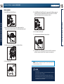
Break-in procedure
1.
2.
3.
Turn the air pressure regulator knob (B) counter-clockwise until it stops.
4. Plug in the power cord (E). NOTE: A circuit breaker is recommended.
If the air compressor is connected to a circuit protected by a
dual element time delay fuses (type “T” only).
fuse, use
OPERATING INSTRUCTIONS
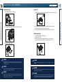
5. Set the ON/OFF switch (H) to the OFF position. The compressor will start. Run the compressor for
30 minutes. If it fails, turn it off immediately and call the toll-free helpline at 1-800-689-9928.
Please note that breaking-in the unit is only required prior to first use.
6. After 30 minutes, turn off the switch.
7. Close the tank drain valve (K) by turning it clockwise direction.
8. Set the ON/OFF switch to the ON (H) position. The air receiver will fill to cut-out pressure
and then the compressor’s motor will stop. The compressor is now ready for use.
CAUTION!
Use a dedicated circuit.
For best performance and reliable starting, the air compressor should be plugged into a dedicated circuit,
as close as
possible to the fuse box or circuit breaker.
The compressor will use the full capacity of a typical 15 A household circuit. If any other electrical
devices are drawing from the compressor’s circuit, the air compressor may fail to start. Low voltage
or an overloaded circuit can result in sluggish starting that causes the motor thermal overload protector
or circuit breaker to trip, especially in cold conditions.
model no. 058-1892-4 | contact us 1-800-689-9928
Set the ON/OFF switch (H) to the OFF position.
Open the tank drain valve (K) by turning it counter-clockwise to permit the air
to escape and prevent air pressure build-up in the air tank during the break-in period.

headline bars
continuation tabs
notes
warnings
headline bars
continuation tabs
notes
warnings
16 17
OPERATING INSTRUCTIONS
OPERATING INSTRUCTIONS
WARNING!
Risk of bursting. Too much air pressure causes a hazardous risk of bursting. Check the manufacturer’s
maximum pressure rating for air tools and accessories. The regulator outlet pressure must never exceed
the maximum pressure rating.
If the pump has been transported or turned upside down (even partially), allow the pump to sit in a normal,
upright position for approximately 10 minutes before starting.
High temperatures are generated by the electric motor and the pump. To prevent burns or other injuries,
DO NOT touch the air compressor while it is running. Allow it to cool before handling or servicing. Keep
children away from the air compressor at all times.
WARNING!
WARNING!
CAUTION!
Escaping air and moisture can propel debris that may cause eye injury. Wear safety goggles when opening the
drain valve.
WARNING!
To avoid personal injury, always shut off and unplug the unit, and relieve all air pressure from the system before
performing any service on the air compressor.
Risk of unsafe operation. Unit cycles automatically when power is on. When performing maintenance, you may be
exposed to voltage sources, compressed air or moving parts. Personal injuries can occur. Before performing any
maintenance or repair, disconnect power source from the compressor and bleed off all air pressure.
WARNING!
Before each start-up
1. Set the ON/OFF switch (H) to the OFF position.
2. Turn the air pressure regulator knob (B) counter-clockwise until it stops.
3. Attach hose (J) and accessories.
How to start
1. Close the tank drain valve (K) by turning in a clockwise direction. Plug in the power cord (E).
2. Set the ON/OFF switch to the ON (H) position and allow the tank pressure to build.
Motor will stop when tank pressure reaches cut-out pressure.
3. Turn the air pressure regulator knob clockwise until desired pressure is reached.
Shut down procedure
1. Set the ON/OFF switch (H) to the OFF position.
2. Unplug the power cord (E).
3.
model no. 058-1892-4 | contact us 1-800-689-9928
Reduce the pressure in the tank through the outlet hose. You can also pull the
pressure relief valve ring (C) and keep it open to relieve pressure in the tank.

headline bars
continuation tabs
notes
warnings
headline bars
continuation tabs
notes
warnings
18 19
MAINTENANCE
Unplug the power cord(E).
6.
MAINTENANCE
ITEM DESCRIPTION/REASON SERVICE
INTERVAL
Drain
the tank
Daily
Clean
the air
lter warm, soapy water. Allow to dry thoroughly.
Weekly
Test for
leaks
Check that all connections are tight. Small leaks in the tank, hoses,
connections or transfer tubes will substantially reduce the air compressor
and tool performance. Spray a small amount of soapy water around the
area of suspected leaks with a spray bottle. If bubbles appear, repair,
replace or re-seal the faulty component. Do not overtighten any
connections.
Monthly
Storage
Before storing the air compressor, do the following:
• Drain all moisture from the tank (see "To drain tank" in the
Maintenance section of this manual for the correct procedure).
• Use an air blow gun to clean all dust and debris from the compressor.
• Disconnect and wind up the power cord.
• Drain all moisture from the tank.
• Pull the pressure safety valve to release all pressure from the tank.
• Cover the entire unit to protect it from moisture and dust.
• Store the air compressor in a clean and dry location.
• In cold weather, store the compressor in a warm building when it is
not in use. This will reduce problems related to starting the motor and
the freezing of water condensation.
Prior to
storing
Through normal operation of your air compressor, condensation water
will accumulate in the tank. To prevent corrosion of the tank from the
inside, condensation must be drained at the end of every workday.
• Set the ON/OFF switch to the OFF position.
• Unplug the power cord.
• Turn air pressure regulator knob counter-clockwise to set the outlet
pressure to zero.
• Pull and hold ring on safety valve, allowing air to bleed from the
tank until air pressure is minimized.
• Place suitable container under unit to catch water.
• Slightly tilt unit and turn drain valve counter-clockwise to open.
• After the water has been drained, close the drain valve (clockwise).
The air compressor can now be stored.
Note: Allow unit to cool before draining tank. Drain valve becomes hot
during operation.
Check
the valve
Pull/activate the safety valve daily to ensure that it is operating properly
and to clear the valve of any possible obstructions. Daily
To check safety valve
• Before starting compressor, pull the ring on the safety valve (C) to
make sure that the safety valve operates freely. If the valve is stuck or
does not operate smoothly, contact a trained service technician.
To drain tank
1. Set the ON/OFF switch (H) to the OFF (O) position.
2.
3.
Turn air pressure regulator knob (B) counter-clockwise to set the outlet pressure to zero.
4.
Pull and hold ring on the safety valve (C), allowing air to bleed from the tank until air pressure
is minimized.
5.
Place suitable container under unit to catch water.
Slightly tilt unit and turn drain valve (K) counter-clockwise to open.
7. After the water has been drained, close the drain valve (K) (clockwise). The air compressor can now
be stored.
NOTE: Allow unit to cool before draining tank. Drain valve (K) becomes hot during operation.
NOTE: Troubleshooting problems may have similar causes and solutions.
Disconnect the electrical plug and disconnect any tools from air supply before attempting any adjustment.
NOTE:
If any of the following symptoms appears while operating the product, stop using the product immediately,
or serious personal injury could result.
WARNING!
Disconnect the electrical plug and disconnect any tools from air supply before attempting any adjustment.
WARNING!
model no. 058-1892-4 | contact us 1-800-689-9928

headline bars
continuation tabs
notes
warnings
headline bars
continuation tabs
notes
warnings
20 21
TROUBLESHOOTING
TROUBLESHOOTING
model no. 058-1892-4 | contact us 1-800-689-9928
The motor will
not run or start.
The power cord is not plugged in. Plug the power cord into a grounded outlet.
The ON/OFF switch is in the
OFF (O) position. Set the ON/OFF switch to the ON (I) position.
The extension cord is the wrong
wire gauge or is too long. 7 for the proper wire gauge and cord length.
The motor’s thermal overload
protection has tripped.
Turn the air compressor off, unplug the
Check extension cord information page
power cord and wait until the motor has
cooled down. Plug in the power cord only
after the motor has cooled down, and wait
at least 15 minutes to make sure the
thermal overload protector has recovered.
A fuse has blown or a circuit
breaker has been tripped.
Replace the fuse or reset the circuit breaker.
Verify that the fuse has the proper amperage.
Check for low voltage conditions. Disconnect
any other electrical appliances from the
circuit or operate the compressor on a
dedicated circuit.
The air tank pressure exceeds
the preset pressure switch limit.
The motor will start automatically when the
tank pressure drops below the cut-in
pressure.
The safety valve is stuck open. Clean or replace the safety valve.
Electrical connections are loose.
Have the compressor serviced by a qualified
technician.
The motor, capacitor or safety
valve is defective.
Have the compressor serviced by a qualified
technician.
The pressure switch does not
shut off the motor when the air
compressor reaches the cut-out
pressure and the safety valve
activates.
Set the ON/OFF switch to the OFF position.
If the motor does not shut off, unplug the air
compressor. If the pressure switch is
defective, replace it.
The compressor’s capacity
is not enough.
Check air requirements of the accessory
that is being used. If it is higher than the
CFM (Cubic Feet per Minute, page 4)
and pressure supplied by the compressor, a
larger capacity air compressor is needed.
Most accessories are rated at 25% of actual
CFM while running continuously.
PROBLEM POSSIBLE CAUSES SOLUTIONS
The motor runs
continuously
when the
pressure switch
is in the ON
position.
PROBLEM POSSIBLE CAUSES
SOLUTIONS
The regulator
does not
regulate the
pressure.
The regulator or its internal parts
are dirty or damaged. Replace the regulator.
The pressure is
low or there is
not enough air.
There is a leak at one of the
fittings.
Check the fittings with soapy water. Tighten
or reseal leaking fittings (apply plumber's tape
on threads). Do not overtighten.
The tank drain valve is open. Close the drain valve.
Prolonged excessive use of air.
The air intake is restricted.
Decrease the amount of air used.
There is a hole in the air hose.
Replace the tank immediately. Do not attempt
to repair it.
Check for worn parts and replace them if
necessary.
CAUTION: Always replace a damaged gauge
before operating the unit again.
The tank leaks.
The check valve/pressure relief
valve/pressure regulating valve
is leaking.
Check the air hose and replace it if necessary.
There is
moisture in the
discharge air.
There is condensation in the air
tank caused by a high level of
atmospheric humidity or because
the air compressor has not been
running long enough.
Drain the air tank after each use. Drain the air
tank more often in humid weather and use an
air line filter.
The
compressor
overheats.
The ventilation is inadequate. Relocate the compressor to an area with cool,
dry and well-circulated air.
Cooling surfaces are dirty. Clean all cooling surfaces on the pump and the
motor thoroughly.
The check valve is leaking. Replace worn parts and reassemble using new
plumber's tape.

headline bars
continuation tabs
notes
warnings
headline bars
continuation tabs
notes
warnings
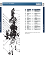
No. Description Qty.
No. Description Qty.
22 23
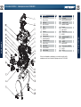
EXPLODED VIEW
TSIL STRAP
1
2
3
4
5
6
7
8
9
10
11
12
13
14
If any parts are missing or damaged, or if you have any questions, please call our toll-free
helpline at 1-800-689-9928.
19
20
21
22
101
102
103
104
105
106
107
108
15
16
17
18
Upper handle
Lower handle
Top shroud
Mufer tube
Motor
Windshield
Pressure switch
Cord clamp
Bottom shroud
Power cord
Rocker switch
Check valve
Air tank
Rubber foot
Drain valve
Quick coupler
Pressure regulating valve
Safety valve
1
1
1
1
1
1
1
1
1
1
1
1
1
4
1
1
1
1
Control panel
Pressure gauge
Metal hose
Shock pad
Screw M5x6
Screw M6x14
Lock washer Ø5
Hexagon socket bolt M8x35
Screw M5x12
Screw ST4.2
Flat washer Ø8
Screw ST3.9
1
2
1
3
2
2
3
4
1
11
2
3
model no. 058-1892-4 | contact us 1-800-689-9928

headline bars
continuation tabs
notes
warnings
headline bars
continuation tabs
notes
warnings
24 25
WARRANTY
WARRANTY
These warranties are subject to the following conditions and limitations:
A. A bill of sale verifying the purchase and purchase date must be provided;
B. This warranty will not apply to any product or part thereof which is worn or broken or which has
become inoperative due to abuse, misuse, accidental damage, neglect or lack of proper installation,
operation or maintenance (as outlined in the applicable owner’s manual or operating instructions) or
which is being used for industrial, professional, commercial or rental purposes;
C. This warranty will not apply to normal wear and tear or to expendable parts or accessories that may
be supplied with the product which are expected to become inoperative or unusable after a
reasonable period of use;
D. This warranty will not apply to routine maintenance and consumable items such as, but not limited to,
fuel, lubricants, vacuum bags, blades, belts, sandpaper, bits, fluids, tune-ups or adjustments;
E. This warranty will not apply where damage is caused by repairs made or attempted by others (i.e.,
persons not authorized by the manufacturer);
F. This warranty will not apply to any product that was sold to the original purchaser as a reconditioned
or refurbished product (unless otherwise specified in writing);
G. This warranty will not apply to any product or part thereof if any part from another manufacturer is
installed therein or any repairs or alterations have been made or attempted by unauthorized persons;
H. This warranty will not apply to normal deterioration of the exterior finish, such as, but not limited to,
scratches, dents, paint chips, or to any corrosion or discolouring by heat, abrasive and chemical
cleaners; and
I. This warranty will not apply to component parts sold by and identified as the product of another
company, which shall be covered under the product manufacturer’s warranty, if any.
Additional Limitations
This warranty applies only to the original purchaser and may not be transferred. Neither the retailer
nor the
manufacturer shall be liable for any other expense, loss or damage, including, without limitation, any
indirect,
incidental, consequential or exemplary damages arising
in connection with the sale, use or inability
to use this product.
Notice to Consumer
This warranty gives you specific legal rights, and you may have other rights, which may vary from province
to province. The provisions contained in this warranty are not intended to limit, modify, take away from,
disclaim or exclude any statutory warranties set forth in any applicable provincial or federal
legislation.
This Mastercraft product is guaranteed for a period of three (3) years from the date of original retail purchase
against defects in workmanship and materials, except for the following component:
Component A: Accessories, which are guaranteed for a period of one (1) year from the date of original retail
purchase against defects in workmanship and materials.
Subject to the conditions and limitations described below, this product, if returned to us with proof of
purchase within the stated warranty period and if covered under this warranty, will be repaired or replaced
repair or replacement and any costs of labour relating thereto.
(with the same model, or one of equal value or specication), at our option. We will bear the cost of any
Made in China
Imported by Mastercraft Canada Toronto, Canada M4S 2B8
model no. 058-1892-4 | contact us 1-800-689-9928
®

headline bars
continuation tabs
GUIDE
D’UTILISATION
IMPORTANT :
Veuillez lire et comprendre entièrement ce guide d'utilisation avant
d'utiliser cet article. ll contient des informations importantes pour votre
sécurité ainsi que des conseils sur son fonctionnement et son entretien.
3 GALLONS US (11,3 L)
Modèle nº 058-1892-4
COMPRESSEUR D’AIR

headline bars
continuation tabs
notes
warnings
headline bars
continuation tabs
notes
warnings
3
TABLE DES MATIÈRES
REMARQUE :
Si des pièces sont manquantes ou endommagées, ou si vous avez des questions, veuillez composer le
1 800 689-9928.
CONSERVEZ CES INSTRUCTIONS
Conservez ce guide pour toute référence ultérieure. Si vous cédez cet article à une tierce partie,
veuillez également lui donner ce guide d utilisation.
TABLE DES MATIÈRES
FICHE TECHNIQUE 4
CONSIGNES DE SÉCURITÉ 5
SCHÉMA DES PIÈCES CLÉS 8
LISTE DES PIÈCES CLÉS 9
USAGE PRÉVU 10
ASSEMBLAGE 12
CONSIGNES D’UTILISATION 14
ENTRETIEN 18
DÉPANNAGE 20
VUE ÉCLATÉE 22
23
GARANTIE
LISTE DES PIÈCES
24
N° de modèle : 058-9315-2 I Communiquez avec nous au 1 800 689-9928

headline bars
continuation tabs
notes
warnings
headline bars
continuation tabs
notes
warnings
headline bars
continuation tabs
notes
warnings
headline bars
continuation tabs
notes
warnings
headline bars
continuation tabs
notes
warnings
4 5
FICHE TECHNIQUE
CONSIGNES DE SÉCURITÉ
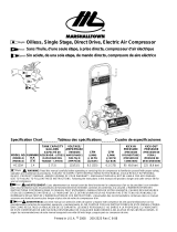
FICHE TECHNIQUE
1,5 HP
3,0 PI³/MIN
135
105
PUISSANCE EN MARCHE
DIMENSION DU RÉSERVOIR
3 GALLONS US (11,3 LITRES)
DÉBIT D'AIR À 40 LB/PO²
DÉBIT D'AIR À 90 LB/PO²
PRESSION MAXIMALE (LB/PO²)
MODÈLE DE POMPE SANS HUILE
MOTEUR UMC
PUISSANCE 120 V, 60 Hz, 12 A
POIDS 24 lb 11 oz (11,2 kg)
CORDON D’ALIMENTATION
* pi³/min : pieds cubes par minute.
SJT 16 AWG / 72 po (1,83 m)
2,2 PI³/MIN
IMPORTANT!
Renseignements importants sur le fonctionnement, l'installation et l'entretien mais non liés au danger.
ATTENTION!
Danger pouvant
entraîner
des blessures légères ou des dommages matériels.
AVERTISSEMENT!
Danger pouvant entraîner des blessures graves ou mortelles.
DANGER!
Danger potentiel qui entraînera inévitablement des blessures graves ou mortelles.
Ce guide contient des renseignements relatifs à la PROTECTION DE LA SÉCURITÉ
PERSONNELLE et à la PRÉVENTION DES PROBLÈMES D'ÉQUIPEMENT. Il est très
important de lire attentivement ce guide et de le compremdre avant d'utiliser l'article.
Les symboles ci-dessous sont utilisés pour indiquer ces renseignements.
CONSIGNES DE SÉCURITÉ
N° de modèle : 058-1892-4 I Communiquez avec nous au 1 800 689-9928
PRESSION D'ENCLENCHEMENT (LB/PO²)
1.
RISQUE D'INCENDIE OU D'EXPLOSION.
à au moins 20 pi (6 m) de la zone à pulvériser. Ne transportez pas et n'utilisez pas le
compresseur ou tout autre appareil électrique près de la zone de pulvérisation. Ne fumez
jamais en pulvérisant. Employez un tuyau d'au moins 25 pi (7,6 m) pour brancher un pistolet
pulvérisateur au compresseur.
2.
RISQUE DE CHOC ÉLECTRIQUE. N’exposez pas l’appareil à la pluie ou à l’eau. Rangez à
l'intérieur. Tension dangereuse. Débranchez de la source d'alimentation avant l'entretien. Le
compresseur doit être mis à la terre. N'utilisez pas d'adaptateurs de mise à la terre.
3. RISQUE DE BLESSURES. Ne dirigez jamais un jet d'air ou de matériau comprimé vers soi ou
autrui.
4. RISQUE D'ÉCLATEMENT.
l'étiquette de l'appareil. La pression de sortie du compresseur doit être réglée de manière à ne
pas excéder la pression maximale. Libérez toute pression se trouvant dans le tuyau avant d'y
fixer ou d’y retirer un accessoire. Assurez-vous que le régulateur de pression soit réglé de sorte
que la pression sortante soit inférieure à la pression maximale de fonctionnement du pistolet ou
de l'outil à pulvériser. Avant de démarrer le compresseur, tirez l'anneau se trouvant sur la soupape
de sûreté pour vous assurer qu'elle bouge librement (voir schéma à la page 19). Videz l'eau du
réservoir après chaque utilisation. Ne soudez pas et ne réparez pas le réservoir.
dans tout espace confiné. La zone de pulvérisation doit être bien aérée. Gardez le compresseur
Ne pulvérisez pas de liquide inammable ou
combustible ni de la peinture à proximité d'étincelles, de ammes, d'une lampe témoin, ni
Vériez la pression nominale maximale dans le manuel ou sur

headline bars
continuation tabs
notes
warnings
headline bars
continuation tabs
notes
warnings
6 7
CONSIGNES DE SÉCURITÉ
SPECIFIC SAFETY GUIDELINES FOR THE SLIDING WET TILE SAW
CONSIGNES DE SÉCURITÉ
AVERTISSEMENT!
Tirez l’anneau de la soupape de sûret
fonctionne correctement.
Le compresseur doit être situé dans un endroit bien ventilé pour se refroidir et doit être à un
minimum de 12 po (31 cm) du mur le plus près .
Protégez le tuyau à air et le cordon d’alimentation contre les dommage et la perforation. V toutes
les semaines s'ils ont des points faibles ou d’usure et remplacez-les au besoin.
Portez toujours des protecteurs auditifs lorsque vous utilisez un compresseur d'air. Le non-respect de
cette consigne pourrait entraîner une perte auditive.
Ne transportez pas le compresseur lorsqu’il est en marche.
Ne faites pas fonctionner le compresseur s'il n'est pas dans une position stable.
Ne faites pas fonctionner le compresseur sur un toit ou dans une position élevée qui pourrait faire
tomberou basculer l’appareil.
Remplacez toujours un manomètre endommagé avant de remettre l'appareil en marche.
RALLONGES ÉLECTRIQUES
tension importante ainsi qu'une perte de puissance, ce qui risque d'endommager l'appareil. Veuillez
* Déterminé de façon à limiter la chute de tension à 5 V, à 150 % de l'intensité.
Plus le numéro de calibre est petit, plus la rallonge est puissante. Par exemple, une rallonge de calibre 14
peut transporter un courant plus élevé qu'un rallonge de calibre 16. Lorsque vous devez raccorder plusieurs
requis.
Directives pour l'utilisation de rallonges électriques
•
•
Assurez-vous que la rallonge est bien branchée et en bon état. Remplacez toujours immédiatement une
rallonge endommagée ou demandez à ce qu’elle soit réparée par un technicien qualié.
Protégez votre rallonge des objets pointus, de la chaleur excessive et des endroits humides ou mouillés.
Plus l'appareil est loin de la source d'alimentation, plus le calibre des ls de la rallonge à utiliser doit
Calibre minimal recommandé pour les rallonges* (120 V)
être élevé. L'utilisation d'une rallonge dont les ls sont de calibre insufsant entraînera une chute de
rallonges, assurez-vous que le calibre des ls de chacune d’elles est égal ou supérieur au calibre minimal
N° de modèle : 058-1892-4 I Communiquez avec nous au 1 800 689-9928
CALIBRE DE LA RALLONGE (CALIBRAGE AMÉRICAIN NORMALISÉ DES FILS)
Longueur de la rallonge
25 pi (7,6 m) 50 pi (15 m) 75 pi (23 m) 100 pi (30 m) 150 pi (46 m) 200 pi (60 m)
0 – 5 16 16 16 14 12
5,1 – 8 16 16 14 12 —
8,1 – 12 14 14 12 10 —
12,1 – 15 12 12 10 10 —
15,1 – 20 10 10 10 —
12
10
—
—
— —
INTENSITÉ
NOMINALE
5. RISQUE D'ÉCLATEMENT. N'ajustez pas l'interrupteur de pression ni la soupape de sûreté
sous aucun prétexte. Ils ont été préréglés en usine pour la pression maximale
correspondant à ce compresseur. Altérer l'interrupteur de pression ou la soupape de
sûreté pourrait causer des blessures ou des dommages matériels.
6. RISQUE DE BRÛLURE.
d'éviter des brûlures et autres blessures, ne touchez pas à la pompe, au collecteur ni au
tube de transfert lorsque le compresseur est en marche. Attendez que les pièces se
refroidissent avant de les manipuler ou de procéder à l'entretien. Gardez les enfants loin du
compresseur en tout temps.
7.
8.
RISQUE D'INHALATION. Assurez-vous de bien lire toutes les étiquettes lorsque vous
pulvérisez de la peinture ou des matières toxiques et conformez-vous à toutes les consignes
de sécurité. Portez un masque de protection respiratoire s'il y a un risque d'inhaler ce que
vous pulvérisez. De plus, n'inhalez jamais directement l'air produit par un compresseur.
RISQUE DE BLESSURES AUX YEUX. Portez des lunettes de sécurité approuvées ANSI Z87.1
ou CSA Z94.3 quand vous utilisez un compresseur d’air. Ne pointez jamais une buse ou un
pulvérisateur en direction de quelqu'un ou de toute partie du corps. Des blessures graves
peuvent se produire si le jet pénètre la peau.
9. RISQUE DE PERTE D'AUDITION. Portez toujours des protecteurs d'oreilles lorsque vous
utilisez un compresseur d’air. Dans le cas contraire, il y a risque de perte d’audition.
La pompe et le collecteur génèrent des températures élevées. An

headline bars
continuation tabs
notes
warnings
headline bars
continuation tabs
notes
warnings
8 9
SCHÉMA DES PIÈCES CLÉS
LISTE DES PIÈCES CLÉS
AVERTISSEMENT!
Ne dépassez pas la limite de pression maximale de l'appareil.
AVERTISSEMENT!
N'essayez pas d'ouvrir la soupape de sûreté lorsqu'il y a plus de 10 lb/po² de pression d'air dans le réservoir.
Fiche
Broche de mise à la terre
Prises de courant
avec mise à la terre
A. Réservoir d'air : C'est dans ce réservoir que l'air comprimé est emmagasiné.
B. Régulateur de pression d'air: Le régulateur est utilisé pour ajuster la pression à l'intérieur du
conduit à l'outil qui est utilisé. Tournez le bouton dans le sens horaire pour augmenter la pression et dans le sens
antihoraire pour diminuer la pression.
C. Soupape de sûreté : Cette soupape sert à empêcher une défaillance du système en évacuant la
pression lorsque son niveau atteint un seuil pré-déterminé, quand le manostat n'a pas éteint le moteur. Elle
s'ouvre automatiquement ou peut être activée manuellement en tirant l'anneau sur la soupape.
D. Manomètre du réservoir : Le manomètre mesure le niveau de pression de l'air emmagasiné dans le
réservoir. Il ne peut être réglé par l'utilisateur et n'indique pas la pression à l'intérieur du tuyau.
E. Cordon d'alimentation : Ce compresseur doit être utilisé sur un circuit nominal de 120 V mis à la terre.
Utilisez un cordon de mise à la terre muni d'une che de mise à la terre. Vériez que le compresseur soit
branché à une prise dont la conguration est la même que la che. N'utilisez pas d'adaptateur pour brancher
ce compresseur à une prise différente.
H. Interrupteur marche/arrêt : Cet interrupteur met en marche et en arrêt le compresseur. ll est actionné
manuellement et lorsqu’il est en position MARCHE (ON), il permet au moteur de démarrer si la pression dans le
réservoir d’air est inférieure à la pression d’enclenchement réglée en usine et il permet au moteur d’arrêter si
la pression dans le réservoir d’air atteint la pression de déclenchement réglée en usine. Assurez-vous de placer
l’interrupteur en position ARRÊT (OFF) lorsque le compresseur n’est pas utilisé et avant de le débrancher.
I. Manomètre de refoulement : Le manomètre sert à mesurer la pression de sortie régulée.
F. Manomètre du réservoir : Le manomètre mesure le niveau de pression de l'air emmagasiné dans le
réservoir. Il ne peut être réglé par l'utilisateur et n'indique pas la pression à l'intérieur du tuyau.
J. Sortie d'air : la sortie d'air est connectée à un tuyau d'air NPT de 1/4 po (6,4 mm).
G. Pompe du compresseur d’air : La pompe comprime l'air et le refoule dans le réservoir par
l'intermédiaire du piston se déplaçant de haut en bas dans le cylindre.
K. Soupape de drainage du réservoir d'air : La soupape de drainage sert à libérer l'humidité de l'air
contenu dans le réservoir après avoir arrêté le compresseur.
N° de modèle : 058-1892-4 I Communiquez avec nous au 1 800 689-9928
F
G
K
B
HE
J
C
A
D
I

headline bars
continuation tabs
notes
warnings
headline bars
continuation tabs
notes
warnings
10 11
USAGE PRÉVU
USAGE PRÉVU
Avant de commencer
Ce compresseur d’air MastercraftMD est idéal pour une grande variété d’applications, comme la
la pression optimale. ll comporte un moteur à induction de 1,5 HP pour un fonctionnement silencieux
xation de pièces, le graissage et le nettoyage de moteur. Son réserviur de 3 gallons (11,3 L) fournit
et une pompe sans huile en fonte pour une durabilité et un rendement optimaux.
Les procédures décrites dans le présent guide sont uniquement pour ce compresseur d’air de 3 gallons US
(11,3 L) d'une pression maximale de 135 lb/po². L'appareil a été conçu et fabriqué pour usage domestique
seulement.
Utilisation adéquate du compresseur et d'un outil pneumatique compatibles
Assurez-vous de toujours utiliser des outils pneumatiques compatibles aves votre compresseur d'air
MastercraftMD. Assurez-vous que le compresseur d’air en fonctionnement peut fournir le volume, la pression
et la débit d’air appropriés á l'outil sans fonctionner de façon continue. L'utilisation d'un outil ou d'une
combinaison d'outils qui, ensemble ou séparément, nécessitent plus de force que le comresseur ne peut en
offrir entraîera l'annulation de la garantie du compresseur.
AVERTISSEMENT!
Ce compresseur n'est pas conçu pour fonctionner en continu ou pour des usages commerciaux
illimités et ne doit servir qu'en milieu sec. Ce compresseur d’air est destiné à être utilisé dans des
intervalles de 30 minutes au plus et doit reposer pendant 30 minutes avant d'être réutilisé. Ne
dépassez pas le temps limite d'utilisation de l'appareil.
Outils pneumatiques
Tableau de compatibilité d’outils
Fonctionnement
continu
Utilisation
déconseillée
Fonctionnement
intermittent
Réglage de pression
(calibre 16)
Cloueuse de charpente
Cloueuse de parquet
Meuleuse à matrices
Meuleuse angulaire
Cliquet pneumatique
Cloueuse pour clous à tête
de diamant (calibre 18)
Cloueuse pour clous à tête
de diamant/cloueuse de
Cloueuse de toiture
Clé à chocs
Pistolet de graissage/de
calfeutrage
Outil à tronçonner
Pistolet à peinture
Perceuse/Mateau/
Ciseau/Cisailles
Ponceuse/Polisseuse
N° de modèle : 058-1892-4 I Communiquez avec nous au 1 800 689-9928

headline bars
continuation tabs
notes
warnings
headline bars
continuation tabs
notes
warnings
12 13
ASSEMBLAGE
ASSEMBLAGE
Remarque : ll faut un tuyau à air de ¼ po (6,4 mm) NPT pour la connexion au compresseur d’air.
Assemblage
1.
a été endommagé, communiquez avec le détaillant immédiatement.
La boîte devrait contenir :
• Un compresseur d’air
• Un guide d’utilisation
2.
le modèle prévu et que ce dernier possède la pression nominale requise pour son usage prévu.
3. Positionnement du compresseur d'air :
• Placez le compresseur d'air près d’une prise électrique.
• Le compresseur doit être à au moins 12 po (31 cm) de tout mur ou obstacle, dans un endroit
• Placez le compresseur d'air sur le sol ou une surface dure et de niveau. Le compresseur d’air doit
'humidité du réservoir.
4. Raccorder le tuyau à air au compresseur
• Raccordez le tuyau à air à la sortie d 'air (J) du compresseur.
N° de modèle : 058-1892-4 I Communiquez avec nous au 1 800 689-9928
12 po (31 cm)
mur
Vériez l’étiquette d’identication du compresseur d’air pour vous assurer que vous avez acheté
La page est en cours de chargement...
La page est en cours de chargement...
La page est en cours de chargement...
La page est en cours de chargement...
La page est en cours de chargement...
La page est en cours de chargement...
-
 1
1
-
 2
2
-
 3
3
-
 4
4
-
 5
5
-
 6
6
-
 7
7
-
 8
8
-
 9
9
-
 10
10
-
 11
11
-
 12
12
-
 13
13
-
 14
14
-
 15
15
-
 16
16
-
 17
17
-
 18
18
-
 19
19
-
 20
20
-
 21
21
-
 22
22
-
 23
23
-
 24
24
-
 25
25
-
 26
26


MasterCraft 3-Gallon Electric Le manuel du propriétaire
- Catégorie
- Compresseurs d'air
- Taper
- Le manuel du propriétaire
dans d''autres langues
Documents connexes
Autres documents
-
 Canadian Tire Branded MotoMaster 400 Lumen Flexible USB Rechargeable LED Worklight Le manuel du propriétaire
-
Maximum 10-Gallon Quiet Cabinet Le manuel du propriétaire
-
-
 Marshalltown Company DUOFLEX HC125A Mode d'emploi
-
 Marshalltown Company DUOFLEX HC125A Manuel utilisateur
-
Porter-Cable PXCMLC1683066 Manuel utilisateur
-
-
Industrial Air IL1682066.MN Manuel utilisateur
-
Craftsman 921.16473 Le manuel du propriétaire
-
 Sanborn Mfg P1682066.MN Manuel utilisateur


