Samlexpower BGW 400 Le manuel du propriétaire
- Taper
- Le manuel du propriétaire

DESCRIPTION
The Battery Guard Waterproof BGW400 (hereafter
referred to as the BGW) is an intelligent, user-
programmable, fully waterproof battery guard.
The BGW has additional options for a remote off
switch and an alarm output for connecting a buzzer,
LED strip or relay. To ensure low losses, the BGW is
provided with two threaded rod and nut connections;
input+ and output+. The other connections (Minus-,
Remote Off-, Cong-input and Status/alarm output)
are connected via 6.3 mm faston connectors.
The BGW is equipped with a bright status LED
displaying the different functional stages. The BGW
features an “automatic board system detection”,
this enables to automatically detect if the BGW is
connected to a 12 V or a 24 V system.
INSTALLATION
Install the BGW on a cooling (metal) surface allowing
to dissipate the heat generated. Use a maximum
cable length of 50 cm between the battery and the
BGW will ensure accurate monitoring the battery
voltage.
Please note!
• The product may only be installed by qualied
electricians who are fully aware of the require-
ments for working with high battery voltages.
• The use of poor/ bad connection material and/or
wires that are too thin can damage the BGW.
• A short circuit between the battery’s positive and
negative terminals can cause serious damage to
the system.
• Always use fuses of the correct value.
• Use a 1.5 mm2 cable with 5A fuse for the
BGW400 from the battery (-) to the BGW for the
negative (–) connection. Use this connection only
for the BGW!
• In case of high inductive loads, always use a
suppressor diode from OUT+ to min (–). Position it
as close as possible to the load.
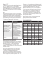
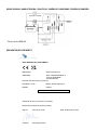
WIRING DIAGRAM (please see last page)
OPERATION
Input voltage protection
The input voltage protection values (undervoltage
threshold, undervoltage reset, overvoltage threshold
and overvoltage reset) can be set by the user.
Please see “CONFIGURE/Programming” how to
set these values.
Undervoltage
If the BGW’s input voltage drops below the
undervoltage threshold for 15 seconds, the status/
alarm output will turn on. The LED will also indicate
undervoltage. The BGW will shut down one minute
later and the alarm output and LED will turn off.
When the BGW’s input voltage exceeds the reset
threshold for 5 seconds, the BGW will turn back on,
and the LED will indicate that the BGW is active again.
Overvoltage
The BGW will shut down if the input voltage exceeds
the overvoltage threshold for 0.5 seconds.
The status/alarm output and LED will ash/switch
with a frequency of 1 Hz.
Overcurrent protection
The current through the BGW is constantly monitored.
If an excessive current ows through the BGW for
too long, the BGW will shut down to prevent damage
to both the BGW and the connected equipment.
The BGW will turn on again after 1 minute.
Temperature protection
The BGW will shut down immediately if its
temperature exceeds 85 °C. The LED will indicate
a fault. The BGW will turn on again after 1 minute if
the temperature has dropped below 75 °C.
Ground Loss protection
The BGW will shut down if it detects that the minus
(–) is disconnected on the supply (battery) side.
The LED will indicate a fault. The BGW will turn on
again after 1 minute.
OWNERS MANUAL EN
Battery Guard Waterproof BGW400

Remote off
A switch can be installed between the OFF input and
the minus (–) to manually disable the BGW output.
The BGW will shut down immediately when the
connection is made. The BGW will turn on when
the connection has been disconnected.
LED
The LED has two functions. One is to indicate the
BGW’s status. The different stages are explaned in
the LED STATUS below. The other is to congure/
programme the BGW. This operation is described in
the section “CONFIGURE/Programming”.
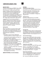
LED STATUS STAGE EXPLAINED
Led is on. BGW has enabled
(switched on) the output.
Two short blinks (then off
for a longer period).
BGW is disabled because
the remote off has been
activated.
One blink (1 second on
and 1 second off).
Undervoltage or
overvoltage detected.
Three short blinks (then off
for a longer period).
BGW has been shut down
for one minute due to one
of the following causes:
Ground loss, temperature
protection, current
protection, low output
voltage.
LED is off. BGW has been shut down
due to undervoltage.
CONFIGURE/PROGRAMMING
To enter the congure/programming mode, a
connection has be made between the CONFIG
input and the Minus (–). The LED will blink one
time when the connection has been made for
approx. 2 seconds. Once this is done, the
connection has to be disconnected.
The same connection can be made briey (short) again
to set the correct position from the programming
table. The LED will light up as feedback.
At that point, program position #1 is selected.
The user can briey (short) make the connection
again to select programme position #2, etc., etc..
If no connection is made for approx. 4 seconds,
the LED will display the set state again.
(Example: programme position #4 is set by a user,
the LED will blink 4 times)
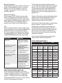
Two types of settings are available. Positions 1
through 10 set the undervoltage threshold and reset
values. Positions 11 and 12 set the overvoltage
threshold and reset values. These settings must be
selected individually.
The programmed positions are also retained when
the battery voltage is disconnected.
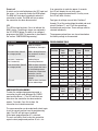
PROGRAMMING TABLE
12V 24V
UNDERVOLTAGE (V)
Position Thres-
hold
Reset Thres-
hold
Reset
1* 10.5 12 21 24
2 10 11.5 20 23
3 9.5 11.5 19 23
4 11.25 13.25 22.5 26.5
5 11.5 13.8 23 27.6
6 10.5 12.8 21 25.6
7 11.5 12.8 23 25.6
8 11.8 12.8 23.6 25.6
9 12 13 24 26
10 10 13.2 20 26.4
OVERVOLTAGE (V)
Position Thres-
hold
Reset Thres-
hold
Reset
11* 16 15.8 32 31.6
12 15.4 15.2 30.8 31.4
* Factory default

GEBRUIKSAANWIJZING NL
OMSCHRIJVING
De Battery Guard Waterproof BGW400 (hierna BGW
genoemd) is een intelligente, door de gebruiker
programmeerbare, volledig waterdichte batterij-
bewaker. De BGW heeft extra mogelijkheden voor
een uitschakelaar en een alarmuitgang voor het
aansluiten van een zoemer, ledstrip of relais.
Om lage verliezen te garanderen is de BGW voorzien
van twee draad- en moerverbindingen; ingang+ en
uitgang+. De overige aansluitingen (Minus-, Remote
Off-, Cong-input en Status/alarm output) worden
aangesloten via 6,3 mm faston connectoren.
De BGW is uitgerust met een heldere status-LED
die de verschillende functionele stadia weergeeft.
De BGW is voorzien van een “automatic board
system detection”, waardoor automatisch kan
worden gedetecteerd of de BGW is aangesloten
op een 12 V- of een 24 V-systeem.
INSTALLATIE
Monteer de BGW op een koelend (metalen) opper-
vlakte zodat deze de ontwikkelde warmte kwijt
kan. Gebruik een maximale kabellengte van 50 cm
tussen de accu en de BGW voor een nauwkeurige
bewaking van de accuspanning.
Let op!
• Het product mag alleen door vakbekwame
installateurs/monteurs, die op de hoogte zijn van
de voorschriften voor het werken met hoge accu
spanningen, worden aangesloten.
• Bij gebruik van slecht aansluitmateriaal en/of te
dunne kabels kan de BGW beschadigen.
• Kortsluiting tussen de plus en min aansluiting van
de accu kan uw systeem beschadigen.
• Gebruik altijd zekeringen (met de juiste waarde).
• Gebruik een 1,5 mm2 kabel met 5A zekering voor
de BGW400 van de accu (-) naar de BGW
negatieve (–) aansluiting. Gebruik deze aansluiting
alleen voor de BGW!
• Gebruik bij hoge inductieve belastingen altijd een
blusdiode van OUT+ naar min (–). Plaats deze zo
dicht mogelijk bij de belasting.
AANSLUITSCHEMA (zie laatste bladzijde)
WERKING
Ingangsspanningsbeveiliging
De waarden van de ingangsspaningsbeveiliging -
onderspanning drempel, onderspanning reset,
overspanning drempel en overspanning reset -
zijn door de gebruiker instelbaar. Hoe dit te
doen is te lezen in het onderdeel “Congureren/
Programmeren”.
Onderspanning
Wanneer de ingangsspanning van de BGW
15 seconden onder de onderspanning drempel-
waarde is, zal de status/alarmuitgang inschakelen.
Ook zal de led weergeven dat er onderspanning
is. Één minuut daarna zal de BGW uitschakelen.
Ook zullen de status alarmuitgang en de led
uitschakelen. Zodra de ingangsspanning van de
BGW 5 seconden boven de resetwaarde is, zal
de BGW inschakelen. De led zal nu ook weer
weergeven dat de BGW is ingeschakeld.
Overspanning
De BGW zal uitschakelen indien de ingangsspaning
van de BGW 0,5 seconden boven de overspanning
drempelwaarde komt. De status/alarmuitgang en LED
knipperen/schakelen met een frequentie van 1 Hz.
Overstroombeveiliging
De stroom door de BGW wordt continue gemeten.
Wanneer er te lange tijd een te grote stroom door
de BGW loopt, zal de BGW uitschakelen om bescha-
digingen aan zowel de BGW als de aange sloten
apparatuur te voorkomen. Na 1 minuut zal de BGW
weer inschakelen.
Temperatuur beveiliging
Wanneer de temperatuur van de BGW hoger wordt
dan 85 °C, zal de BGW direct uitschakelen.
De led zal weergeven dat er een “probleem” is.
Na 1 minuut zal de BGW weer inschakelen indien
de temperatuur onder de 75 °C is gezakt.
Ground Loss beveiliging
Zodra de BGW detecteert dat aan de accu kant de
min (–) is losgekoppeld zal de BGW uitschakelen.
De led zal weergeven dat er een “probleem” is.
Na 1 minuut zal de BGW weer inschakelen.

Remote “OFF”
Er kan een schakelaar worden geïnstalleerd tussen
de “OFF”-ingang en de min (–) om de BGW-
uitgang handmatig uit te schakelen. De BGW wordt
direct uitgeschakeld als de verbinding tot stand is
gebracht. De BGW gaat weer aan als de verbinding
is verbroken.
LED
De led heeft twee functies. De ene is het aangeven
in welke status de BGW zich bevind. De verschillende
mogelijkheden worden hieronder bij LED STATUS
bescheven. De andere functie is het programmeren
van de BGW. Deze werking wordt in het onderdeel
“Congureren/Programmeren” beschreven.
LED STATUS FASE UITLEG
Led is aan. BGW is aan en uitgang is
ingeschakeld.
Led knippert 2x kort,
daarna langer uit.
BGW is uitgeschakeld
doordat de OFF remote is
geactiveerd.
Led knippert 1x (1,0 sec.
aan en 1,0 sec uit).
Er is onderspanning of
overspanning.
Led knippert 3x kort,
daarna langer uit.
BGW is één minuut uit
door één van de volgende
oorzaken: Ground Loss,
temperatuurbeveiliging,
stroombeveiliging,
lage uitgangspanning.
Led is uit. BGW is uit door
onderspanning.
CONFIGUREREN/PROGRAMMEREN
Om de programmeer modus op te starten moet er
een verbinding gemaakt worden tussen de CONFIG
ingang en de minus (–). Nadat de verbinding
± 2 seconden gemaakt is, zal de led 1 maal
knipperen. Zodra dit gebeurd is, moet de verbinding
verbroken worden.
Om het juiste positienummer in te stellen moet
dezelfde verbinding weer kort gemaakt worden
– de led zal als terugkoppeling oplichten.
Op dat moment is programma positie #1 gekozen.
Wanneer de gebruiker nogmaals kort de verbinding
maakt, is programma positie #2 gekozen, etc., etc..
Wanneer er ±4 seconden geen verbinding gemaakt
is, zal de led de ingestelde stand nogmaals weergeven.
(Voorbeeld: programma positie #4 is door een
gebruiker ingesteld, de led zal 4 maal knipperen.)
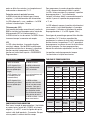
Er zijn twee type instellingen die gemaakt kunnen
worden. Positie 1 t/m 10 stellen de drempel- en
resetwaarden voor onderspanning in. Positie 11
en 12 stellen de drempel- en resetwaarden voor
overspanning in. Deze instellingen moeten los van
elkaar gemaakt worden.
Bij het loshalen van de accuspanning blijven de
geprogrammeerde posities behouden.
PROGRAMMEERTABEL
12V 24V
ONDERSPANNING (V)
Positie Drempel Reset Drempel Reset
1* 10,5 12 21 24
2 10 11,5 20 23
3 9,5 11,5 19 23
4 11,25 13,25 22,5 26,5
5 11,5 13,8 23 27,6
6 10,5 12,8 21 25,6
7 11,5 12,8 23 25,6
8 11,8 12,8 23,6 25,6
9 12 13 24 26
10 10 13,2 20 26,4
OVERSPANNING (V)
Positie Drempel Reset Drempel Reset
11* 16 15,8 32 31,6
12 15,4 15,2 30,8 31,4
* Fabrieksinstellingen

BESCHREIBUNG
Der Battery Guard Waterproof BGW400 (nachstehend
„BGW“ genannt) ist ein intelligenter, benutzer-
programmierbarer, komplett Batteriewächter.
Der BGW hat Erweiterungsmöglichkeiten wie einen
Aus-Schalter und einen Alarm-Ausgang, an den
ein Summer, eine LED-Leiste oder ein Relais
angeschlossen werden kann. Um geringe Verluste
zu gewährleisten, ist das BGW mit zwei Anschluss-
bolzen ausgestattet: Eingang+ und Ausgang+.
Die übrigen Anschlüsse (Minus-, Remote Off-,
Cong-Eingang und Status/Alarm-Ausgang) werden
über 6,3 mm Faston stecker angeschlossen.
Der BGW ist außerdem mit einer gut ablesbaren
LED-Zustandsanzeige ausgestattet, woran der
Benutzer den Betriebszustand des BGW ablesen
kann. Außerdem ist der BGW mit einer „automatischen
Platinensystem-Erkennung“ ausgestattet, sodass
der BGW automatisch erkennt, ob er an ein 12 V-
oder 24 V-System angeschlossen ist.
INSTALLATION
Der BGW sollte auf einer kühlenden Unterlage
(aus Metall) montiert werden, damit die entstehende
Wärme abgeleitet werden kann. Verwenden Sie eine
maximale Kabellänge von 50 cm zwischen der
Batterie und dem BGW, um eine genaue Über-
wachung der Batteriespannung zu gewährleisten.
Achtung!
• Das Produkt darf nur von fachkundigen
Installateuren/Monteuren angeschlossen werden,
die mit den Vorschriften für die Arbeit mit hohen
Akkuspannungen vertraut sind.
• Bei Nutzung von schlechten Anschlussmaterialien
und/oder zu dünnen kabel kann der BGW
beschädigt werden.
• Ein Kurzschluss zwischen dem Plus- und Minusan-
schluss des Akkus kann Ihr System beschädigen.
• Immer Sicherungen (mit dem richtigen
Nennstromwert) verwenden.
• Verwenden Sie für den negativen (–) Anschluss
ein 1,5 mm2 Kabel mit 5A Sicherung für das
BGW400 von der Batterie (-) zum BGW.
Diesen Anschluss nur für die BGW verwenden!
• Bei hohen induktiven Lasten ist immer eine
Löschdiode zwischen OUT+ und Minus (-) zu
verwenden. Diese ist so nah wie möglich an der
Belastung anzubringen.
SCHALTPLAN (SIEHE LETZTE SEITE)
FUNKTIONSWEISE
Betriebsspannungsschutz
Die Werte für den Betriebsspannungsschutz –
Schwellwert für die Unterspannung, Wiedereinschal-
tung nach Unterspannung, Schwellwert für die
Überspannung und Wiedereinschaltung nach
Überspannung – können vom Benutzer eingestellt
werden. Wie das geht, wird im Kapitel „Kongurieren/
Programmierung“ beschrieben.
Unterspannung
Wenn die Betriebsspannung des BGW 15 Sekunden
lang den Grenzwert für die Unterspannung
unterschreitet, wird der Status/Alarm-Ausgang
aktiviert. Die LED zeigt auch Unterspannung an.
Nach einer Minute schaltet sich der BGW ab.
Auch der Alarm-Ausgang und die LED schalten
sich ab. Sobald die Betriebsspannung des BGW
5 Sekunden lang über dem Reset-Wert liegt, schaltet
sich der BGW wieder ein. Die LED zeigt nun auch
wieder an, dass der BGW eingeschaltet ist.
Überspannung
Der BGW schaltet sich aus, falls die Betriebsspannung
des BGW 0,5 Sekunden über dem Schwellwertfür
die Überspannung liegt. Außerdem zeigt der Status/
Alarm-Ausgang (mit einer Frequenz von 1 Hz) an,
dass eine Überspannung erkannt wurde. Diese
Informationen werden auch über die LED angezeigt.
Überstromschutz
Der durch den BGW ießende Strom wird ständig
gemessen. Wenn zu lange ein zu hoher Strom
durch den BGW ießt, schaltet sich der BGW ab, um
Schäden am BGW und dem angeschlossenen Gerät
zu vermeiden. Nach 1 Minute schaltet sich der BGW
wieder ein.
Temperaturschutz
Wenn die Temperatur des BGW über 85 °C ansteigt,
schaltet sich der BGW sofort aus. Die LED zeigt dann
an, dass ein „Problem“ vorliegt. Nach 1 Minute schaltet
sich der BGW wieder ein, wenn die Temperatur unter
75 °C gesunken ist.
GEBRAUCHSANWEISUNG DE

Masseschlussschutz
Sobald der BGW erkennt, dass der Minus-Anschluss (–)
von der Zufuhrseite getrennt wurde, schaltet der
BGW sich aus. Die LED zeigt dann an, dass ein
„Problem“ vorliegt. Nach 1 Minute schaltet sich
der BGW wieder ein.
Remote-OFF Eingang
Durch Anschluss eines Schalters zwischen dem
Remote OFF-Eingang und dem Minus-Anschluss
(–) kann der BGW-Ausgang manuell ausgeschaltet
werden. Wenn ein Kontakt hergestellt wird, schaltet
sich der BGW sofort aus. Wenn dieser Kontakt
getrennt wird, schaltet sich der BGW wieder ein.
LED
Die LED hat zwei Funktionen. Erstens zeigt sie den
Stand des BGW an. Die verschiedenen Möglichkeiten
werden LED-STATUS nachstehend beschrieben.
Die zweite Funktion ist die Kongurieren/Program-
mierung des BGW. Dieses Funktion wird im Kapital
„KONFIGURIEREN/Programmierung“ beschrieben.
LED-STATUS ERKLÄREN
LED ist an. BGW hat den Ausgang
freigegeben (eingeschal-
tet).
LED blinkt 2x kurz (dann
längere Zeit aus).
Der BGW wurde durch
Aktivierung der
Remote-OFF Funktion
ausgeschaltet.
LED blinkt 1x (1 Sekunde
an und 1 Sekunde aus).
Es liegt eine Über- oder
Unterspannung vor.
LED blinkt 3x kurz (dann
längere Zeit aus).
Der BGW bleibt aufgrund
einer der folgenden Urs-
achen eine Minute abge-
schaltet: Masseschluss-
schutz, Temperaturschutz,
Stromschutz, niedrige
Ausgangsspannung.
LED ist aus. Der BGW hat sich
aufgrund von Unterspann-
ung abgeschaltet.
KONFIGURIEREN/PROGRAMMIERUNG
Um den Programmierungsmodus zu aktivieren,
muss eine Verbindung zwischen Programmeingang
“CONFIG” und Minus-Anschluss (–) hergestellt
werden. ± 2 Sekunden nach der Herstellung der
Verbindung blinkt die LED einmal auf. Gleich danach
muss die Verbindung getrennt werden.
Zum Einstellen der korrekten Positionsnummer
muss die gleiche Verbindung erneut kurz hergestellt
werden – die LED leuchtet als Rückmeldung auf.
In diesem Moment wurde Programmposition Nr. 1
gewählt. Wenn der Nutzer noch einmal kurz eine
Verbindung herstellt, wird Programmposition Nr. 2
gewählt, usw.
Sobald ±4 Sekunden lang keine Verbindung besteht,
zeigt die LED erneut den eingestellten Status an.
(Beispiel: Wenn vom Benutzer Programm Nr. 4
eingestellt wurde, blinkt die LED vier Mal.)
Zwei Arten von Einstellungen können vorgenommen
werden: Position 1 bis einschl. 10 dient zur
Einstellung der Schwellwerte und der Werte für
die Rücksetzung nach Unterspannung. Position 11
und 12 dient zur Einstellung der Schwellwerte und
Werte für die Rücksetzung nach Überspannung.
Diese Einstellungen müssen getrennt voneinander
vorgenommen werden.
Beim Trennen der Batteriespannung werden die
programmierten Positionen beibehalten.
PROGRAMMIERUNGSTABELLE
12V 24V
UNTERSPANNUNG (V)
Position Schwell-
wert
Rückset-
zung
Schwell-
wert
Rückset-
zung
1* 10,5 12 21 24
2 10 11,5 20 23
3 9,5 11,5 19 23
4 11,25 13,25 22,5 26,5
5 11,5 13,8 23 27,6
6 10,5 12,8 21 25,6
7 11,5 12,8 23 25,6
8 11,8 12,8 23,6 25,6
9 12 13 24 26
10 10 13,2 20 26,4
ÜBERSPANNUNG (V)
Position Schwell-
wert
Rückset-
zung
Schwell-
wert
Rückset-
zung
11* 16 15,8 32 31,6
12 15,4 15,2 30,8 31,4
* Werkseinstellung

DESCRIPTION
Le Battery Guard Waterproof BGW400 (ci après
nommé BGW) est un système de surveillance
de batterie intelligent et entièrement étanche,
programmable par l’utilisateur. Il est possible
d’ajouter un interrupteur au BGW et une sortie
d’alarme sur laquelle brancher un vibreur sonore,
une bande LED ou un relais. Pour garantir des
pertes les plus faibles possibles, le BGW comporte
une connexion par deux boulons ; Entrée+ et
sortie+. Les autres connexions(min (MINUS), télé
alimentation (OFF), alimentation programmable
(CONFIG) et sortie d’alarme (STATUS) ) sont réalisées
par le biais de connecteurs faston de 6,3 mm
distincts. Le BGW est de plus doté d’une LED d’état
indiquant son mode de fonctionnement. Le BGW
possède également une « détection automatique
de système » permettant au BGW de déterminer
automatiquement s’il est raccordé à un système
12 V, ou 24 V.
SCHÉMA
Installez le BGW sur une surface de refroidissement
en métal, an de permettre l’évacuation du surplus
de chaleur. Utiliser une longueur de câble maximale
de 50 cm entre la batterie et le BGW assurera une
surveillance précise de la tension de la batterie.
Attention !
• Le produit ne peut être installé que par des
installateurs/monteurs qualiés et informés des
prescriptions en matière de fonctionnement de
dispositifs à haute tension.
• L’utilisation de matériaux de raccordement
inappropriés et/ou de ls électriques de trop
petite section peut endommager le BGW.
• Un court-circuit entre la borne négative et la
borne positive de la batterie peut endommager
votre système.
• Utilisez toujours des fusibles (de puissance
adéquate).
• Utilisez un câble de 1,5 mm2 avec un fusible 5A
pour le BGW400 de la batterie (-) au BGW pour la
connexion négative (–). Utilisez cette connexion
uniquement pour le BGW !
• En cas de charges d’induction élevées, toujours
monter une diode de suppression de tension
transitoire congurée de la borne de sortie OUT+
vers la borne de pôle négatif (–). Placer cette
diode le plus proche possible de la charge.
SCHÉMA DES CONNEXIONS (Veuillez consulter
la dernière page)
MODE DE FONCTIONNEMENT
Protection contre la surtension d’alimentation
L’utilisateur peut programmer les valeurs de
protection contre la surtension d’alimentation :
le seuil de sous-tension, la réinitialisation de
la sous-tension, le seuil de surtension et la
réinitialisation de surtension. La procédure à ces
ns est abordée dans la partie « CONFIGURER/
Programmation ».
Sous-tension
La sortie d’alarme est activée lorsque la tension
d’alimentation du BGW passe pendant 15 secondes
sous la valeur minimale de sous-tension. La LED
indique également la sous-tension. Une minute plus
tard, le BGW s’éteint, ainsi que la sortie d’alarme
et la LED. Le BGW s’active lorsque la tension
d’alimentation reste pendant 5 seconde au-dessus
de la valeur de réinitialisation. À ce moment-là,
la LED indique également que le BGW est activé.
Surtension
Le BGW s’éteint lorsque sa tension d’alimentation
dépasse la valeur seuil de surtension pendant
0,5 seconde De plus, la sortie d’alarme (STATUS)
indique la présence de surtension (à une fréquence
de 1 Hz). Cette information est également
communiquée par la LED.
Protection contre la surcharge
L’électricité qui passe par le BGW est constamment
mesurée. Si une surtension est constatée
durablement dans le BGW, ce dernier s’éteint pour
sa propre protection et la protection de l’appareil
branché sur le BGW. Le BGW s’allume à nouveau
après 1 minute.
Protection contre la surchauffe
Le BGW s’éteint immédiatement lorsque sa
température dépasse 85 °C. La LED indique qu’il
y a un « problème ». Le BGW s’allume à nouveau
MODE D’EMPLOI FR

après un délai d’une minute si sa température est
redescendue en-dessous de 75 °C.
Protection contre la perte de la masse
Le BGW s’éteint dès qu’il détecte que la borne
négative (–) a été déconnectée côté alimentation.
La LED indique qu’il y a un « problème ». Le BGW
s’allume à nouveau après 1 minute.
Télécommande (OFF)
Il est possible de couper manuellement la sortie du
BGW en installant un interrupteur entre l’entrée de
télécommande (OFF) et la borne négative (–).
Le BGW s’éteint en cas de contact. Le BGW s’allume
à nouveau lorsque la connexion est coupée.
LED
La LED a deux fonctions. La première fonction
consiste à indiquer l’état du BGW. Les différentes
possibilités sont décrites ci-dessous. La deuxième
fonction consiste à programmer le BGW. Cette
fonction est traitée dans la partie « CONFIGURER/
Programmation ».
ÉTAT DE LA LED RAISON
La LED est allumée. Le BGW est activé.
La LED clignote 2 fois
brièvement (puis éteint
pour une période plus
longue).
Le BGW est désactivé,
car la télécommande
(OFF) est activée.
La LED clignote 1 fois
(1 seconde allumé et
1 seconde éteint).
Il y a soit surtension, soit
sous-tension.
La LED clignote 3 fois
brièvement (puis éteint
pour une période plus
longue).
Le BGW est éteint
pendant une minute du
fait de l'une des causes
suivantes : Perte par la
terre, protection thermi-
que, protection contre
les variations de courant,
faible tension de sortie.
LED éteinte. Le BGW est éteint à cause
d'une sous-tension.
CONFIGURER/PROGRAMMATION
Pour lancer le mode de programmation, il faut établir
un contact entre l’entrée de « CONFIG» et la borne
négative (–) La LED 1 se met à clignoter dès qu’un
contact a été établi pendant ± 2 secondes. Dès que
cela se produit, le contact doit être rompu.
Pour programmer le numéro de position adéquat,
il faut à nouveau brièvement rétablir le contact.
La LED s’allume en retour. À ce moment, la position
de programmation n° 1 est sélectionnée.
Lorsque l’utilisateur établit à nouveau brièvement le
contact, il passe à la position de programmation
n° 2, etc.
La LED indique à nouveau la position sélectionnée si
aucun contact n’a été établi pendant ±4 secondes
(par exemple : l’utilisateur a sélectionné la position
de programmation n° 4, la LED clignote 4 fois.)
Deux types de paramétrages peuvent être effectués.
Les positions 1 à 10 incluse, permettent de
programmer les valeurs de seuil et de réinitialisation
de sous-tension. Les positions 11 et 12, permettent
de programmer les valeurs de seuil et de réinitialisa-
tion de surtension. Ces deux programmations
doivent être effectuées séparément l’une de l’autre.
Les positions restent programmées lorsque
l’accumulateur n’est plus sous tension.
TABLEAU DE PROGRAMMATION
12V 24V
SOUS-TENSION (V)
Position Seuil Réinitia-
lisation
Seuil Réinitia-
lisation
1* 10,5 12 21 24
2 10 11,5 20 23
3 9,5 11,5 19 23
4 11,25 13,25 22,5 26,5
5 11,5 13,8 23 27,6
6 10,5 12,8 21 25,6
7 11,5 12,8 23 25,6
8 11,8 12,8 23,6 25,6
9 12 13 24 26
10 10 13,2 20 26,4
SURTENSION (V)
Position Seuil Réinitia-
lisation
Seuil Réinitia-
lisation
11* 16 15,8 32 31,6
12 15,4 15,2 30,8 31,4
* Paramètres par défaut

DESCRIPCIÓN
El protector de batería a prueba de agua BGW400
(en lo sucesivo, BGW) es un protector de batería
inteligente, programable por el usuario y
completamente impermeable. El BGW tiene
opciones adicionales para un interruptor de apagado
remoto y una salida de alarma para conectar un
zumbador, una tira de LED o un relé. Para garantizar
bajas pérdidas, el BGW está provisto de dos
conexiones de varilla roscada y tuerca; entrada+ y
salida+. Las otras conexiones (Minus-, Remote Off-,
Cong-input y Status/alarm output) se conectan a
través de conectores Faston de 6,3 mm. El BGW
está equipado con un LED de estado brillante que
muestra las diferentes etapas funcionales. El BGW
cuenta con una “detección automática del sistema
de placa”, que permite detectar automáticamente si
el BGW está conectado a un sistema de 12 V o 24 V.
INSTALACIÓN
Instale el BGW sobre una supercie fría (metálica)
para que pueda ir enfriándose. Para la alimentación
del BGW, utilice un cable con una longitud máxima
de 50 cm. Esta es la única manera de garantizar una
tensión exacta.
¡Atención!
• El producto debe ser instalado únicamente por
mecánicos/instaladores profesionales que estén
familiarizados con la normativa para trabajos con
altas tensiones de batería.
• El uso de materiales de conexión inadecuados y/o
de un cableado demasiado no podría ocasionar
daños en el BGW.
• Un cortocircuito en la conexión de polo positivo y
negativo de la batería podría dañar su sistema.
• Utilice siempre fusibles (del valor correcto).
• Para la conexión (–) min, utilice un cable de
1,5 mm2 con fusible de 5A para el BGW400
conectado directamente desde la batería al BGW.
¡Utilice esta conexión solo para BGW!
• Para cargas inductivas elevadas, siempre debe
utilizar un diodo de enfriamiento de salida+ a
menos (–). Posiciónelo lo más cerca posible de
la carga.
ESQUEMA DE CONEXIÓN (Por favor vea la última
página)
FUNCIONAMIENTO
Protección de la tensión entrada
El usuario puede congurar los valores de la
protección de la tensión de entrada, umbral
de subtensión, reseteo de subtensión, umbral
de sobretensión y reseteo de sobretensión.
Para hacer esto, consulte el apartado «CONFIGURAR/
Programación».
Subtensión
Cuando la tensión de entrada del BGW esté
debajo del valor umbral de subtensión durante
15 segundos, se activará la salida de estado/
alarma (STATUS). Además, el LED indicará que
hay subtensión. Un minuto después, el BGW se
desactivará. También se desactivarán la salida
de alarma y el LED. Tan pronto como la tensión
de entrada del BGW esté por encima del valor de
reseteo durante 5 segundos, volverá a encenderse
el BGW. El LED indicará de nuevo que el BGW está
activado.
Sobretensión
El BGW se apagará tan pronto como la tensión de
entrada del BGW esté por encima del valor umbral
de sobretensión durante 0,5 segundos. La salida
de estado/alarma (STATUS) también indicará (con
una frecuencia de 1Hz) que se ha detectado una
sobretensión. Esta información también se indicará
por medio del LED.
Control de sobrecorriente
Se mide constantemente la corriente que pasa por
el BGW. Si pasa demasiada corriente por el BGW
durante demasiado tiempo, este se desactivará
a n de impedir que se dañe tanto el BGW como
cualquier otro dispositivo que esté conectado.
Después de 1 minuto, el BGW volverá a activarse.
Control de temperatura
Si la temperatura del BGW supera los 85 °C, este
se apagará automáticamente. El LED mostrará un
mensaje de que existe un «problema». Después de
1 minuto, el BGW volverá a activarse si se ha enfriado
a una temperatura por debajo de los 75 °C.
MANUAL DEL PROPIETARIO ES

Control de pérdida de suelo
Tan pronto como el BGW detecte que en el lateral
de alimentación el min (–) está suelto, el BGW se
desactivará. El LED mostrará un mensaje de que
existe un «problema». Después de 1 minuto, el BGW
volverá a activarse.
Apagado Remoto
Al conectar un interruptor entre la entrada del
remote (OFF) y el min(–), es posible desactivar
la salida BGW, manualmente. Al establecer esta
conexión, el BGW se desactivará automáticamente.
Al eliminarse esta conexión, el BGW volverá a
activarse.
LED
El LED tiene dos funciones. La primera es indicar
en qué estado se encuentra el BGW. Las diferentes
posibilidades se describen a continuación.
La segunda función es la programación del BGW.
Esta función se describe en el apartado
«CONFIGURAR/Programación».
ESTADO DEL LED EXPLICANDO
El LED está encendido. El BGW se ha desactivado.
El LED parpadea
brevemente dos veces
(luego apagado por un
período más largo).
EL BGW se ha desactivado
debido a que el remote
(OFF) está activado.
El LED parpadea una vez
(luego apagado por un
período más largo).
Existe subtensión o
sobretensión.
El LED parpadea tres
veces (luego apagado por
un período más largo).
El BGW se apaga durante
un minuto por uno de
los siguientes motivos:
Pérdida de suelo, control
de temperatura, seguridad
de corriente, baja tensión
de salida.
El LED se ha apagado. EL BGW se ha apagado
debido a subtensión.
CONFIGURAR/PROGRAMACIÓN
Para iniciar el modo de congurar/programación,
debe establecerse una conexión entre la entrada de
«CONFIG» y el min (–). Una vez se haya establecido
la conexión durante ± 2 segundos, el LED
parpadeará una vez.Tan pronto como esto ocurra,
deberá interrumpirse la conexión.
A n de ajustar el número de posición correcto,
deberá cortarse de nuevo la misma conexión;
el LED se encenderá como retroalimentación.
En ese momento se elige la posición de programa
núm. 1. Tan pronto como el usuario vuelva a cortar
la conexión, se seleccionará la posición de programa
n.º 2, etc.
Tan pronto como deje de establecerse una conexión
durante unos 4 segundos, el LED volverá a indicar
la posición programada. (Por ejemplo, si un usuario
congura la posición de programa n.º 4, el LED
parpadeará 4 veces.)
Pueden realizarse dos tipos de conguración.
Las posiciones del 1 al 10 conguran los valores
umbral y de reseteo para la subtensión.
Las posiciones del 11 al 12 conguran los valores
umbral y de reseteo para la sobretensión. Estas dos
conguraciones deben realizarse por separado.
Al desconectar la tensión de la batería, se mantienen
las posiciones programadas.
TABLA DE PROGRAMACIÓN
12V 24V
SUBTENSIÓN (V)
Posición Umbral Reseteo Umbral Reseteo
1* 10,5 12 21 24
2 10 11,5 20 23
3 9,5 11,5 19 23
4 11,25 13,25 22,5 26,5
5 11,5 13,8 23 27,6
6 10,5 12,8 21 25,6
7 11,5 12,8 23 25,6
8 11,8 12,8 23,6 25,6
9 12 13 24 26
10 10 13,2 20 26,4
SOBRETENSIÓN (V)
Posición Umbral Reseteo Umbral Reseteo
11* 16 15,8 32 31,6
12 15,4 15,2 30,8 31,4
* Conguración de fábrica

TECHNICAL DATA
BGW400
ELECTRICAL
Input voltage range 6 … 35 V
Maximum continuous output current (@25 °C) 400 A
Peak current (@25 °C) 2,000 A (±0.6 sec)
Voltage drop 50 mV @ 400 A
Current Output active 3.2 mA
Consumption Output inactive 3.2 mA
Voltage accuracy 2%
Current accuracy 20%
Maximum status/alarm output load 100 mA
INPUT & OUTPUT CONNECTOIN
Minimum wire diameter 120 mm2
Bolt size M10
Cable lugs Cable lugs must match the cable diameter used.
FASTON CONNECTIONS
Minimum wire diameter 1.5 mm2
Faston plug 6.3 mm
MECHANICAL
Mounting hole (Ø) 4.5 mm
Distance between mounting holes (centre to centre) ± 1 mm 190.0 mm & 71.5 mm
Weight 1040 g
Dimensions (H*W*L) ± 1 mm 87.5*52.5*206.0 mm
IP Code IP66
Housing material PU552
Housing colour Black
Cooling concept Convection and conduction.
GENERAL
Operational ambient temperature -10 °C ... +40 °C
Storage temperature -25 °C ... +85 °C
Operational air humidity Up to 95%, non-condensing.
Galvanic insulation No
Remote contact switch-off Yes
PROTECTION
Overcurrent/Short circuit Yes (after 1 minute restart).
Overheating, shutdown Above 85 °C (after 1 minute restart).
Polarity protection Yes, with fuse in the minus (-) line.

DECLARATION OF CONFORMITY
IMPORTER : Samlex Europe B.V.
ADDRESS : ARIS VAN BROEKWEG 15
1507 BA ZAANDAM
The Netherlands
Declares that the following products:
PRODUCT TYPE : Battery Guard Waterproof
BRAND : Samlex
Standards to which conformity is declared:
EN 61000-6-2:2005, EN 61000-6-3:2007
Signed : Marcel van Veen Date: 20 November 2023
Authority : Managing Director
BGW-400
WIRING DIAGRAM / AANSLUITSCHEMA / SCHALTPLAN / SCHÉMA DES CONNEXIONS / ESQUEMA DE CONEXIÓN
DECLARATION OF CONFORMITY
FUSE*
* 5A fuse for the BGW400
-
 1
1
-
 2
2
-
 3
3
-
 4
4
-
 5
5
-
 6
6
-
 7
7
-
 8
8
-
 9
9
-
 10
10
-
 11
11
-
 12
12


Samlexpower BGW 400 Le manuel du propriétaire
- Taper
- Le manuel du propriétaire
dans d''autres langues
- English: Samlexpower BGW 400 Owner's manual
- español: Samlexpower BGW 400 El manual del propietario
- Deutsch: Samlexpower BGW 400 Bedienungsanleitung
- Nederlands: Samlexpower BGW 400 de handleiding