Lifetime 90602 Le manuel du propriétaire
- Taper
- Le manuel du propriétaire

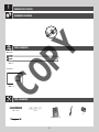
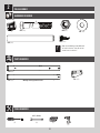
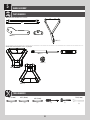
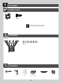
TOOLS REQUIRED TABLE OF CONTENTS
(x2) (x2) (x2) (x2) (x2)
(x1)
(x1)
1/2" (13 mm) 9/16" (14 mm) 11/16" (18 mm) 3/4" (19 mm) 1/2" (13 mm)
Icon Legend................................2
Notices....................................3
Ground Preparation.....................4
Pole Assembly.............................8
Backboard to Rim Assembly......11
Backboard to Pole Assembly.......16
Parts Identifi er..........................i-iv
Handle Assembly......................23
Final Assembly..........................32
Maintenance Instructions..........36
Warning Sticker........................37
Registration........................38
Warranty................................39
(x1)
(x1)
30” Rebar
Cement Mix
Level
(x1)
1/2" (13 mm)
(x1)
(x1)
(x3)
(x1)
CONTACT LIFETIME CUSTOMER SERVICE:
Call: 1-800-225-3865
7:00 am–5:00 pm (Monday–Friday) MST
and 9:00 am–1:00 pm Saturday MST
QUESTIONS?
Model Number: 90602
Product ID:
For Customer Service in Mainland
Europe and the United Kingdom,
E-mail: [email protected]
Live Chat:
www.lifetime.com
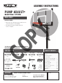
PUMP ADJUST
®
BASKETBALL SYSTEM
BEFORE ASSEMBLY:
• Before you start, decide how you would like to fi ll
your base (sand is recommended).
• Assembly should take 3 people about 3-4
hours to complete.
ASSEMBLY INSTRUCTIONS
MODEL 90602
Save this instruction in the event that the manufacturer has
to be contacted for replacement parts.
COPY

2
• Indicates the parts to be used for a section.
• Indicates special heed should be taken when reading.
• Indicates the hardware to be used for a section.
• Indicates the tools to be used for a section.
• Indicates no hardware required for a specifi c page.
• Indicates no parts required for a specifi c section.
• Indicates to use/not to use an electric drill for a specifi c step.
ICON LEGEND
• Indicates the use of a Centerlock Nut. A Nut with this marking will require some effort to tighten.
This hardware was designed with this feature in order to prevent loosening later.
1184987 C
10/25/2019
COPY

3
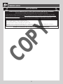
WARNINGS & NOTICES
Most injuries are caused by misuse and/or not following instructions. Use caution when using this product.
To ensure safety, do not attempt to assemble this product without following the instructions carefully. Check entire box and inside all packing
material for parts and/or additional instruction material. Before beginning assembly, read the instructions and identify parts using the hardware
identifi er and parts list in this document. Proper and complete assembly, use and supervision are essential for proper operation and to reduce the
risk of accident or injury. A high probability of serious injury exists if this product is not installed, maintained, and operated properly.
FAILURE TO FOLLOW THESE WARNINGS MAY RESULT IN SERIOUS INJURY OR PROPERTY DAMAGE AND WILL VOID WARRANTY.
Owner must ensure that all players know and follow these rules for safe operation of the system.
• If using a ladder during assembly, use extreme caution.
• Three capable adults are recommended for this operation.
• Check base daily for leakage. Leaks will cause system to fall.
• Assemble the pole sections properly. Failure to do so could cause the pole sections to separate during play or transport.
• Minimum operational height is 6 ft 6 in (1.98m) to the bottom of the backboard.
SAFETY INSTRUCTIONS
COPY

4
1
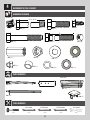
Metal Parts
TOOLS REQUIRED
PARTS REQUIRED
HARDWARE REQUIRED
(1)
(1)
ALE (x1)
30" Rebar
Level
BGW (x1)
Paper Parts
(1)
640 lb / 291 kg
GROUND PREPARATION
COPY

5
TOOLS AND HARDWARE REQUIRED
X SECTION 1 (CONTINUED)
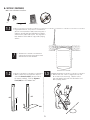
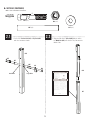
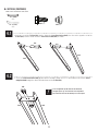
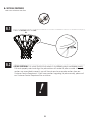
1.1
• A Ground Sleeve is available as an alternative to
cementing the Pole into the ground. Please contact
Customer Service for more information.
!
• Dig a round hole 24" deep and 21" in diameter. If
you live in an area where frost heaves may pose a
problem, consult your local building inspector to
determine the proper hole depth. The edge of the
hole should be fl ush with the edge of the playing
surface.
(1)
(1)
1.2
• Make a mark 16 inches from the dimpled
end of the Bottom Pole (ALE) (do not scratch
the powder coating). Slide the Alignment
Frame (BGW) over the Bottom Pole.
1.3
• Mix the concrete. Save 1/2 bag of concrete mix
to use later in the assembly. Pour the mixed
concrete into the hole until it is fi lled to the level
of the playing surface.
640 lb / 291 kg
(1)
ALE
16”
ALE
BGW

6
TOOLS AND HARDWARE REQUIRED
X SECTION 1 (CONTINUED)
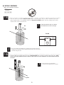
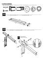
• Slide the dimpled end of the Bottom Pole (ALE) into the cement up to the 16-inch mark. Position the pole next
to the playing surface. For regulation courts, the Alignment Frame (BGW) should cross the playing surface at the
middle of the scored measurements.
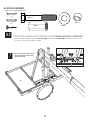
1.4
• Use a Level to make sure the Bottom Pole is standing vertical. Form the cement into a
downward slope away from the pole to allow water runoff. Failure to do so may result in
premature rusting of the Pole.
• If the pole is buried too deep or too shallow,
the rim will not to be at the correct height.
• Do not continue the assembly until the
concrete has been allowed to set for 1-4 hours.
!
!
!
30" Rebar
Playing
Surface
ALE
TOP VIEW
BGW
ALE
• Insert the 30" rebar (not included) inside the Bottom Pole (ALE) so it is about 15" from the top of the pole. Check
the pole several times within the fi rst hour to make sure that all sides are vertical and that the 16-inch mark remains level with
the surface.
1.5
Rebar

7
TOOLS AND HARDWARE REQUIRED
X SECTION 1 (CONTINUED)
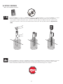
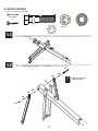
• Mix the remaining 1/2 bag of concrete. Fill the Bottom Pole (ALE) with concrete until it reaches the top of the
rebar (about 15" from the top of the pole). Tamp the concrete down in the Bottom Pole with a broom handle
to remove air pockets. Clean all concrete off the outside of the pole. You may now remove the Alignment Frame
(BGW).
Stop assembly now. Do not continue the assembly until the concrete has been allowed to set for at least 72 hours (3 days). In humid
climates or wet weather, allow more time for the concrete to cure. Do not proceed until the curing process is complete.
1.6
15”

8
POLE ASSEMBLY
2
BCO
Metal Parts
Hardware Bag
TOOLS REQUIRED
PARTS REQUIRED
HARDWARE REQUIRED
(1)
(1)
9/16" (14 mm)
(1)
(2)
• Warning Sticker applied to this Pole
CMV (x2)*
AAA (x2)
AAF (x2)
ANF (x2)
ANE (x2)
5”
• Only one Self-Drilling Screw (CMV) will
be used in Section 2. Save the second
Screw for use in Section 5.
ALH (x1)
ALF (x1)
ALL (x1)
!

9
TOOLS AND HARDWARE REQUIRED
X SECTION 2 (CONTINUED)
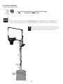
• Secure the Pole Bracket (ALL) to Top Pole (ALH)
with the hardware shown.
2.1
ANE (x2)
ANF (x2)
ALH
ANF
ANE
ALL
AAA
AAF
Large Holes
Small Holes
AAA (x2)
9/16" (14 mm)
(2)
5”
AAF (x2)
ALH
ALF
• Align the hole in the Top Pole (ALH) with the slot in
the Middle Pole (ALF) and slide the Top Pole over the
Middle Pole.
2.2
FAUTE DE NE PAS SUIVRE CES AVERTISSEMENTS, VOUS RISQUEZ DE CAUSER
DES BLESSURES GRAVES ET/OU DES DOMMAGES À L’ÉQUIPEMENT.
Le propriétaire doit s’assurer que tous les joueurs con-
naissent et appliquent les règles suivantes afin d’utiliser
l’équipement en toute sécurité.
SI NO SE OBEDECEN ESTAS ADVERTENCIAS PUEDEN PRODUCIRSE
GRAVES LESIONES Y/O DAÑOS A LA PROPIEDAD.
El propietario del sistema debe asegurarse de que todos
los jugadores conozcan y respeten estas reglas para que el
sistema se use en forma segura.
WARNING
FAILURE TO FOLLOW THESE WARNINGS MAY RESULT IN SERIOUS INJURY
AND/OR PROPERTY DAMAGE.
Owners must ensure that all players know and follow these
rules for safe operation of the system.
• Only hang from the Rim briefly to regain balance or avoid
injuring others. Release the Rim as soon as safely possible.
• During play, especially when performing dunk type activities,
keep player’s face away from the Backboard, Rim, and Net.
Serious injury could occur if teeth/face come in contact with
the Backboard, Rim, or Net. Player should wear a mouth
guard during play.
• Do not slide, climb, or play on Base or Pole.
• When adjusting height or moving system, keep hands and
fingers away from moving parts.
• Do not allow children to move or adjust system.
• Do not wear jewelry (rings, watches, necklaces, etc.) during
play. Objects may entangle in Net.
• Keep water and organic material away from Pole Base. Grass,
litter, etc. could cause corrosion and/or deterioration.
• Never play on damaged equipment.
• Once a month check Pole and all metal parts for signs of
corrosion (rust, pitting, chipping). Completely remove rust and
repaint with exterior enamel. If rust has penetrated any steel
part, replace that part immediately.
• Check system before each use for proper ballast, loose
hardware, excessive wear, instability, and signs of corrosion
and repair before use.
• Do not use the system to lift or hoist anything. The
mechanism is designed to lift only the weight of the
Backboard and Rim. Do not hang anything from the Handle,
Rim, Backboard, or Lifter Arms as this will damage the
system and void the warranty.
• Ne vous suspendez pas à l’anneau plus que nécessaire pour
retrouver votre équilibre ou éviter de blesser les autres joueurs.
Relâchez l’anneau aussitôt que possible.
• Lors d’un match, particulièrement dans le cas des smashs, le
visage du joueur ne doit pas faire face au panneau, à l’anneau, ni au
filet. Le joueur risque de graves blessures si ses dents ou son visage
entrent en contact avec le panneau, l’anneau, ou le filet. Les joueurs
doivent toujours porter un protège-dents lorsqu’ils jouent.
• Ne glissez pas, ne grimpez pas, et ne jouez pas sur la base ou le
poteau.
• Lorsque vous ajustez la hauteur ou lorsque vous déplacez
l’équipement, gardez vos mains et doigts loin des pièces mobiles.
• Ne permettez pas aux enfants de déplacer ou d’ajuster
l’équipement.
• Ne portez pas de bijoux (bagues, montres, colliers, etc.) lorsque
vous jouez. Ces objets pourraient s’accrocher au filet.
•Gardez de l’eau et de la matiére organique loin de la base. Le
gazon, les déchets, etc. pourraient provoquer la corrosion et/ou la
détérioration.
• Une fois par mois, vérifiez que le Poteau et toutes les pièces en
métal ne montrent pas de signes de corrosion (rouille, piqûres,
écaillage). Enlevez toute la rouille et repeignez complètement avec
une peinture pour extérieur. Si la rouille a pénétré une des pièces en
acier, vous devrez remplacer immédiatement la pièce en question.
• A chaque fois que vous allez utiliser l’équipement, vérifiez d’abord
l’équilibre, la possibilité de pièces desserrées ou usées, la stabilité
de l’équipement et tout signe de corrosion ou réparation nécessaire
avant utilisation.
• Ne jouez jamais avec un équipement endommagé.
• N’utilisez pas l’équipement pour lever ou soulever quoique ce soit.
Son mécanisme a été conçu uniquement pour soutenir le poids du
panneau et de l’anneau. N’accrochez rien au manche, à l’anneau,
au panneau ni aux leviers sous peine d’endommager l’équipement
et d’annuler la garantie.
• Cuélguese del aro sólo en forma breve, para recuperar el equilibrio
o evitar lesionar a otros jugadores. Suéltese del aro lo más pronto
que pueda hacerlo con seguridad.
• Durante el juego, especialmente al embocar violentamente de
alto, la cara de los jugadores debe mantenerse alejada del tablero,
el aro y la red. Pueden producirse lesiones graves si los dientes o la
cara entran en contacto con el tablero, el aro o la red. Los jugadores
deben usar un protector bucal durante el juego.
• No se deslice, no trepe ni juegue sobre la base o el pos te.
•Mantenga las manos y los dedos alejados de las piezas movibles
cuando regule la altura o desplace el sistema.
• No deje que los niños regulen ni desplacen el sistema.
• No use joyas (anillos, relojes, collares o gargantillas, etc.) durante el
juego. Estos objetos pueden engancharse en la red.
• Guarde aqua y materia orgánica. Cé sped, basura,etc., prodrian
causar corrosión et/o deterioros.
• Controle el poste y todas las piezas metálicas una vez al mes
en busca de signos visibles de corrosión (oxidación, picaduras,
escamado). Elimine todo rastro de óxido y vuelva a pintar con
esmalte para exteriores. Si el óxido ha penetrado cualquier pieza de
acero, reemplace esa pieza de inmediato.
• Inspeccione el sistema antes de cada uso para verific ar que esté
adecuadamente contrapesado, que los elementos de fijación no
estén flojos, que no haya desgaste excesivo, inestabilidad ni signos
de corrosión. Si encuentra irregularidades, repárelas antes de usar
el sistema.
• Nunca juegue con un equipo dañado.
•No use el sistema para levantar ningún objeto. El mecanismo está
diseñado para elevar solamente el peso del tablero con el aro. No
cuelgue nada de la agarradera, el aro, el tablero ni los brazos de
elevación, ya que esto puede dañar el sistema y anular la garantía.
www.lifetime.com
# 1176611
ADVERTENCIAAVERTISSEMENT
Lifetime Products, Inc., Clearfield, UT 84016
1-800-225-3865
7/12/2016

10
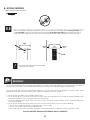
TOOLS AND HARDWARE REQUIRED
X SECTION 2 (CONTINUED)
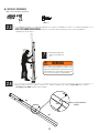
2.3
• Do not hit your feet with the Pole
sections, as serious injury could
occur.
(1)
• THIS STEP CANNOT BE REVERSED! Strike the end of the Pole Assembly on a piece of scrap wood or
cardboard fi ve to six times.
6x
!
(1)
CMV (x1)
CMV
ALH
ALH
ALF
1" up from bottom of
Top Pole
• After the Poles have been seated, measure up 1" from the bottom center of the Top Pole (ALH) and insert one
Self-Tapping Screw (CMV) into the Pole as shown.
2.4
WARNING
The Poles must be seated together! Even if the Poles cover
the slots before seating, they must be struck on a hard
surface five to six times! Failure to seat the Poles correctly
could allow the Poles to separate during use, which could
lead to serious personal injuries or property damage.

11
BACKBOARD TO RIM ASSEMBLY
3
BCS
Hardware Bag
PARTS REQUIRED
HARDWARE REQUIRED
AJI (x1)
Metal Parts
ANK (x4)
ABK (x4)
ADX (x2)
BGZ (x1)
ANL (x1)
5 9/16”
AAX (x1)
ANO (x1)
ABD (x4)
ANM (x2)
ABB (x2)
ANN (x2)
ANJ (x4)
AMB (x1)
AMA (x1)
BGY (x1)
AMC (x1)
AMK (x1)
ALY (x1)
BPZ (x1)
BQA (x1)
ALX (x1)
TOOLS REQUIRED
1/2" (13 mm) 9/16" (14 mm) 3/4" (19 mm)
(x1)
(x2) (x2) (x2)

12
X SECTION 3 (CONTINUED)
TOOLS AND HARDWARE REQUIRED
ANJ (x2)
ABD (x2)
ABK (x2)
3.1
• The Glass Backboard will break if the Rim
Spacer (BGY) is not installed as shown in this
step. This may result in personal injury or
property damage.
!
ANJ
ANJ
ABD
ABD
AMB
AMC
BGY
AJI
ABK
ABK
• Lay the Backboard (AJI) face up with the Rim holes exposed over the edge of a table. Place the Rim Impact Spacer
(BGY) in the Backboard. Add the Left and Right Rim Housings (AMC & AMB) on top of the Rim Impact Spacer and slide
the hardware shown into place.
9/16" (14 mm)
(x2)

13
X SECTION 3 (CONTINUED)
TOOLS AND HARDWARE REQUIRED
3.2
3.3
• Secure the Rim Adapter Plate (ALY) to the Backboard (AJI) by using the hardware as shown.
• Slide the end of the Rim Pin (BPZ) into the Rim (ALX) and through the Eye Bolt (BQA) in the location indicated. Attach
the Rim to the Rim Housing using the hardware shown, making sure the Nylon Washers (ANK) rest between the Rim
and the Rim Housing.
ANJ (x2)
ABD (x2)
ABK (x2)
ABD
ABD
ANJ
ANJ
ALY
ABK
ABK
AJI
BPZ
BQA
ALX
ANK
ANK
ANL
AAX
5 9/16”
ANL (x1)
AAX (x1)
ANK (x2)
1/2" (13 mm)
(x2)
3/4" (19 mm)
(x2)

14
X SECTION 3 (CONTINUED)
TOOLS AND HARDWARE REQUIRED
ANM (x2)
ABB (x2)
ALX
BQA
AMK
ANK (x2)
ANM
ANM
ABB
ABB
3.4
• Slide the Spring Holder Clevis (AMK) onto the Eye Bolt (BQA) and secure with the hardware shown.
ANK
ANK
9/16" (14 mm)
(x2)

15
X SECTION 3 (CONTINUED)
TOOLS AND HARDWARE REQUIRED
3.5
3.6
• Slide the Compression Spring (BGZ) onto the Eye Bolt (BQA), and secure with the hardware shown. Tighten the 3/8” Zinc
Nuts (ANN) to adjust Rim tension.
• Attach the Rim Cover Plate (AMA) to the Rim with the hardware shown.
BQA
ANN
ANN
ANN (x2)
ANO
BGZ (x1)
ANO (x1)
BGZ
ADX (x2)
AMA
ADX
ADX
(x1)
9/16" (14 mm)
(x2)

16
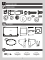
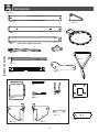
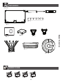
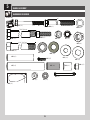
Metal Parts
Hardware Bag
TOOLS REQUIRED
PARTS REQUIRED
HARDWARE REQUIRED
BACKBOARD TO POLE ASSEMBLY
4
(x1) (x2)
(x1) (x1)
1/2" (13 mm)
1/2" (13 mm)
3/4" (19 mm)
11/16" (18 mm)
(x1)
BCR
AAD (x1)
ANQ (x2) AQD (x1)
ANU (x2)
AQB (x2)
ANS (x8)
AAN (x2)
AAX (x4)
7 1/16” (18 cm)
5”
ANP (x1)
AOR (x6)
ABP (x2)
ANK (x4)
AQC (x2)
BGP (x2)
BGO (x2)
BLC (x1)
ANZ (x2)
ABN (x4)
ALM (x1)
Plastic Parts

17
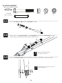
X SECTION 4 (CONTINUED)
TOOLS AND HARDWARE REQUIRED
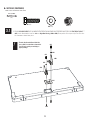
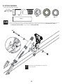
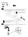
4.1
• Insert one end of the Tie Plate (BLC) into the slot on the Lower Extension Arm (BGP), then iInsert the opposite end of the
Tie Plate (BLC) into the slot on the other Lower Extension Arm (BGP) as shown.
• Do not overtighten the Cap Nut. If the end of the Bolt breaks
through the plastic cap, call our Customer Service Department.
Exposed threads on the end of the Bolt may cause serious injuries.
!
1/2” (13mm)
(x1)
1/2” (13 mm)
(x1)
BLC
BLC
BGP
BGP
AQB
AAN
BGP
BGP
BLC
AQB (x2)
AAN (x2)
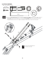
4.2
• Secure the Lower Extension Arms (BGP) together with the hardware shown. Use a 1/2” Socket Wrench to screw the Thread-
Cutting Bolts (AQB) through the Lower Extension Arms and the Tie Plate (BLC).

18
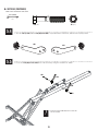
X SECTION 4 (CONTINUED)
TOOLS AND HARDWARE REQUIRED
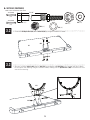
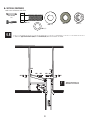
4.3
TOOLS AND HARDWARE REQUIRED / HERRAMIENTAS Y ACCESORIOS REQUERIDOS / OUTILS ET ACCESSOIRES REQUIS
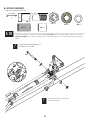
• Insert the Extension Arm Caps (AQC) into the ends of the Lower Extension Arms (BGP) as shown.
X SECTION 4 (CONTINUED)
• Place the Top Pole (ALH) to the Lower Extension Arms (BGP) and secure them with the hardware shown.
4.4
BGP
BGP
AQC
AQC
BGP
AAX
AAD
AOR
AOR
ANZ
ANZ ANZ
ANZ
ALH
• Tighten the Nut until it is
fl ush with the end of the Bolt.
!
AAX (x1)
AAD (x1)
7 1/16” (18 cm)
3/4" (19 mm)
(x2)
ANZ (x2)
AOR (x2)

19
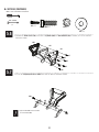
X SECTION 4 (CONTINUED)
TOOLS AND HARDWARE REQUIRED
AAX (x1)
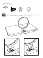
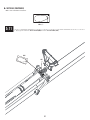
4.6
• Attach the Upper Extension Arms (BGO) to the Top Pole (ALH) with the hardware as shown.
3/4" (19 mm)
(x2)
5”
BGO
BGO
AQD
AAX
ANK
ABN
ABN
ANK
AQD (x1)
ANK (x2)
• Tighten the Nut until it is fl ush
with the end of the Bolt.
!
ABN (x2)
(x1)
4.5
• Insert the Pole Cap (ALM) into the Top Pole as shown. Line up the Pole Cap stirrups with the holes in the top of the Pole.
ALM

20
X SECTION 4 (CONTINUED)
TOOLS AND HARDWARE REQUIRED
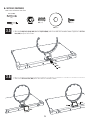
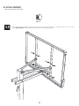
4.7
ANP (x1)
ABP (x2)
AOR (x2)
ANQ (x2)
BGP BGP
AJI
ANQ
ANQ
AOR
AOR
ANP
ABP
ABP
ABP
AOR
AOR
ANQ ANQ
ANP
3/4" (19 mm)
(x2)
11/16" (18 mm)
(x1)
• Rest the Rim on cardboard to prevent scratching, then secure the Lower Extension Arms (BGP) to the Backboard (AJI)
with the hardware shown. Thread the Nut Coupler (ANP) onto one of the Hex Bolts (ANQ), then onto the other. Center
the coupler between the two Bolts as shown.
• Make sure the Poly Spacers (ABP) positioned
between the Lower Extension Arms and the
Backboard do not bulge.
!
(x1)
La page charge ...
La page charge ...
La page charge ...
La page charge ...
La page charge ...
La page charge ...
La page charge ...
La page charge ...
La page charge ...
La page charge ...
La page charge ...
La page charge ...
La page charge ...
La page charge ...
La page charge ...
La page charge ...
La page charge ...
La page charge ...
La page charge ...
La page charge ...
La page charge ...
La page charge ...
La page charge ...
La page charge ...
-
 1
1
-
 2
2
-
 3
3
-
 4
4
-
 5
5
-
 6
6
-
 7
7
-
 8
8
-
 9
9
-
 10
10
-
 11
11
-
 12
12
-
 13
13
-
 14
14
-
 15
15
-
 16
16
-
 17
17
-
 18
18
-
 19
19
-
 20
20
-
 21
21
-
 22
22
-
 23
23
-
 24
24
-
 25
25
-
 26
26
-
 27
27
-
 28
28
-
 29
29
-
 30
30
-
 31
31
-
 32
32
-
 33
33
-
 34
34
-
 35
35
-
 36
36
-
 37
37
-
 38
38
-
 39
39
-
 40
40
-
 41
41
-
 42
42
-
 43
43
-
 44
44


Lifetime 90602 Le manuel du propriétaire
- Taper
- Le manuel du propriétaire
dans d''autres langues
- English: Lifetime 90602 Owner's manual
Documents connexes
-
Lifetime 90602 Le manuel du propriétaire
-
Lifetime 71281 Le manuel du propriétaire
-
-
-
-
-
-
-
-