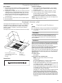
Jenn-Air JXI8742DS Manuel utilisateur
- Catégorie
- Hottes
- Taper
- Manuel utilisateur
Ce manuel convient également à

JENN-AIR
®
36" (91.4 CM) AND 42" (106.7 CM)
ISLAND CANOPY RANGE HOOD
HOTTE DE CUISINIÈRE JENN-AIR
®
POUR ÎLOT DE 36" (91,4 CM) ET 42" (106,7 CM)
Installation Instructions and Use & Care Guide
For questions about features, operation/performance, parts, accessories, or service in the U.S.A., call:
1-800-JENNAIR (1-800-536-6247) or visit our website at www.jennair.com.
In Canada, call: 1-800-JENNAIR (1-800-536-6247), or visit our website at www.jennair.ca.
Instructions d’installation et Guide d’utilisation et d’entretien
Au Canada, pour assistance, installation ou service, composez le 1-800-JENNAIR (1-800-536-6247) ou visitez notre site web à
www.jennair.ca.
Table of Contents/Table des matières ............ 2
IMPORTANT: READ AND SAVE THESE INSTRUCTIONS.
FOR RESIDENTIAL USE ONLY.
IMPORTANT : LIRE ET CONSERVER CES INSTRUCTIONS.
POUR UTILISATION RÉSIDENTIELLE UNIQUEMENT.
2846/W10640310B

2
TABLE OF CONTENTS
RANGE HOOD SAFETY .................................................................3
INSTALLATION REQUIREMENTS ................................................5
Tools and Parts ............................................................................5
Location Requirements................................................................5
Venting Requirements..................................................................6
Electrical Requirements ...............................................................7
INSTALLATION INSTRUCTIONS ..................................................8
Prepare Location..........................................................................8
Install Range Hood.......................................................................9
Make Electrical Connection .......................................................11
Complete Installation .................................................................13
RANGE HOOD USE......................................................................13
Controls and Features................................................................13
RANGE HOOD CARE ...................................................................14
Cleaning......................................................................................14
WIRING DIAGRAM ......................................................................16
ASSISTANCE OR SERVICE.........................................................17
In the U.S.A. ...............................................................................17
In Canada ...................................................................................17
Accessories................................................................................17
WARRANTY ..................................................................................18
TABLE DES MATIÈRES
SÉCURITÉ DE LA HOTTE DE CUISINIÈRE................................19
EXIGENCES D'INSTALLATION...................................................21
Outils et pièces...........................................................................21
Exigences d’emplacement.........................................................21
Exigences concernant l'évacuation ...........................................22
Spécifications électriques ..........................................................23
INSTRUCTIONS D’INSTALLATION.............................................24
Préparation de l’emplacement...................................................24
Installation de la hotte ................................................................26
Raccordement électrique...........................................................28
Achever l’installation ..................................................................29
UTILISATION DE LA HOTTE .......................................................30
Commandes et caractéristiques................................................30
ENTRETIEN DE LA HOTTE..........................................................31
Nettoyage ...................................................................................31
SCHÉMA DE CÂBLAGE ..............................................................33
ASSISTANCE OU SERVICE.........................................................34
Au Canada..................................................................................34
Accessoires ................................................................................34
GARANTIE.....................................................................................35

3
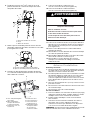
RANGE HOOD SAFETY
You can be killed or seriously injured if you don't immediately
You
can be killed or seriously injured if you don't
follow
All safety messages will tell you what the potential hazard is, tell you how to reduce the chance of injury, and tell you what can
happen if the instructions are not followed.
Your safety and the safety of others are very important.
We have provided many important safety messages in this manual and on your appliance. Always read and obey all safety
messages.
This is the safety alert symbol.
This symbol alerts you to potential hazards that can kill or hurt you and others.
All safety messages will follow the safety alert symbol and either the word “DANGER” or “WARNING.”
These words mean:
follow instructions.
instructions.
DANGER
WARNING
State of California Proposition 65 Warnings:
WARNING: This product contains one or more chemicals known to the State of California to cause cancer.
WARNING: This product contains one or more chemicals known to the State of California to cause birth defects or other
reproductive harm.

4
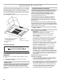
IMPORTANT SAFETY INSTRUCTIONS
READ AND SAVE THESE INSTRUCTIONS

5
INSTALLATION REQUIREMENTS
Tools and Parts
Gather the required tools and parts before starting installation.
Read and follow the instructions provided with any tools
listed here.
Tools needed:
■ Level
■ Drill with 1¼" (3.0 cm), ½" (12.7 mm) and ³⁄₁₆" (5.0 mm)
drill bits
■ Pencil
■ Tape measure or ruler
■ Pliers
■ Caulking gun and weatherproof caulking compound
■ Vent clamps
■ Jigsaw or keyhole saw
■ Flat-blade screwdriver
■ Metal snips
■ Phillips screwdriver
■ ½" (13 mm) socket and driver with 24" (61 cm) of extensions
■ T20
®†
TORX
®
bit or driver
Parts needed:
■ Home power supply
■ ½" (12.7 mm) UL listed or CSA approved strain reliefs
For vented installations, you will also need:
■ 1 wall or roof cap
■ Metal vent system
For non-vented (recirculating) installations, you will
also need:
■ Chimney Kit Recirculation for non-vented (recirculating)
installations only. See “Assistance or Service” section
to order.
■ Charcoal Filter Part Number W10272069. See “Assistance
or Service” section to order.
Parts supplied:
Remove parts from packages. Check that all parts are included.
■ Hood canopy assembly with ventilator and lights installed
■ Mounting boss/damper/6" (15.2 cm) round flexible metal duct
7" (17.8 cm) long (not expanded)
■ Filter - installed in hood canopy
■ (4) 8 x 80 mm hanger bolts (T20
®
TORX
®
drive)
■ (4) 8 mm x ½" (13 mm) hex nuts
■ (4) 5 x 13 mm mounting screws (T20
®
TORX
®
drive)
■ Mounting template
■ Upper chimney cover
■ Lower chimney cover
■ ½" (13 mm) special nut tightening tool
■ Vent clamp for 6" (15.2 cm) duct
■ (2) 3.5 x 9.5 mm screws used for supporting the lower
chimney (located inside canopy behind filters).
Location Requirements
IMPORTANT: Observe all governing codes and ordinances.
Have a qualified technician install the range hood. It is the
installer's responsibility to comply with installation clearances
specified on the model/serial/rating plate. The model/serial/
rating plate is located behind the left filter on the rear wall of
the vent hood.
Canopy hood location should be away from strong draft areas,
such as windows, doors and strong heating vents.
Cabinet opening dimensions that are shown must be used. Given
dimensions provide minimum clearance.
This range hood is recommended for use with cooktops with a
maximum total rating of 78,000 BTUs or less.
Grounded electrical outlet is required. See “Electrical
Requirements” section.
Because of the size and weight of this island hood, the chimney
support must be securely attached to the ceiling.
■ The chimney support must be attached to joists. If this is not
possible, you must build a support structure behind the
plaster or drywall. The support structure must be able to
support 100 lbs (45.4 kg).
The range hood is factory set for venting through the roof or wall.
For non-vented (recirculating) Installation see “Non-vented
(recirculating) Installations” in “Install Range Hood” section.
Chimney Kit Recirculation and Charcoal Filter Kit Part Number
W10272069 are available from your dealer or an authorized parts
distributor. See “Assistance or Service” section to order.
All openings in ceiling and wall where range hood will be installed
must be sealed.
For Mobile Home Installations:
The installation of this range hood must conform to the
Manufactured Home Construction Safety Standards, Title 24
CFR, Part 328 (formerly the Federal Standard for Mobile Home
Construction and Safety, Title 24, HUD, Part 280) or when such
standard is not applicable, the standard for Manufactured Home
Installation 1982 (Manufactured Home Sites, Communities and
Setups) ANSI A225.1/NFPA 501A, or latest edition, or with local
codes.
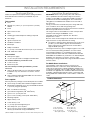
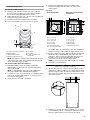
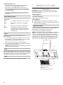
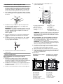
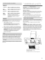
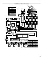
Product Dimensions
†®T20 and TORX are registered trademarks of Acument Intellectual Properties, LLC.
A. 13" (33.0 cm)
B. 11¼" (28.6 cm)
C. 28" (71 cm) min.
45¼" (115 cm) max
D. 2
³⁄₈
" (6.0 cm)
E. 24" (61.0 cm)
F. 36" (91.4 cm)
or 42" (106.7 cm)
B
A
C
D
E
F

6
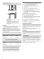
Installation Dimensions
IMPORTANT:
Minimum distance “C”: 24" (61.0 cm) from electric cooking
surface, 30" (76.2 cm) from gas cooking surface
Suggested maximum distance “C”: 36" (91.4 cm)
NOTE: For best performance of the Auto Sense feature, the
range hood should be installed at 24" (61.0 cm) from an electric
cooking surface and 30" (76.2 cm) from a gas cooking surface.
The chimneys can be adjusted for different ceiling heights.
See the following chart.
*NOTE: The range hood chimneys are adjustable and designed
to meet varying ceiling or soffit heights depending on the
distance “C” between the bottom of the range hood and
the cooking surface. For higher ceilings from 10' (3.05 m),
a Stainless Steel Chimney Extension Kit is available from
your dealer or an authorized parts distributor. The chimney
extension replaces the upper chimney shipped with the
range hood. See “Assistance or Service” section to order.
Venting Requirements
■ Vent system must terminate to the outside, except
for non-vented (recirculating) installations.
■ Do not terminate the vent system in an attic or other
enclosed area.
■ Do not use 4" (10.2 cm) laundry-type wall caps.
■ Use metal vent only. Rigid metal vent is recommended.
Do not use plastic or metal foil vent.
■ The vent system must have a damper. If the roof or wall
cap has a damper, do not use the damper supplied with
the range hood.
For the most efficient and quiet operation:
■ Use a straight run or as few elbows as possible.
■ Use no more than three 90° elbows.
■ Make sure there is a minimum of 24" (61.0 cm) of straight
vent between the elbows if more than 1 elbow is used.
■ Do not install 2 elbows together.
■ Use vent clamps to seal all joints in the vent system.
■ Use caulking to seal exterior wall or roof opening around
the cap.
■ The size of the vent should be uniform.
Cold Weather Installations:
An additional back draft damper should be installed to minimize
backward cold air flow and a thermal break should be installed
to minimize conduction of outside temperatures as part of the
vent system. The damper should be on the cold air side of the
thermal break.
The break should be as close as possible to where the vent
system enters the heated portion of the house.
Makeup Air:
Local building codes may require the use of makeup air systems
when using ventilation systems greater than specified CFM of
air movement. The specified CFM varies from locale to locale.
Consult your HVAC professional for specific requirements in
your area.
Venting Methods
This island hood is factory set for venting through the roof.
A 6" (15.2 cm) round vent system is needed for installation (not
included). The hood exhaust opening is 6" (15.2 cm) round.
A 6" to 8" (15.2 cm to 20.3 cm) vent adapter is available for 8"
(20.3 cm) vent systems. See the “Assistance or Service” section
to order.
Vent system can terminate either through the roof or wall.
To vent through a wall, a 90° elbow is needed.
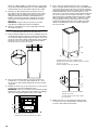
A. Countertop height
B. Hood height from ceiling to bottom of the range
hood: E-A-C=B
C. Hood height: 24" (61.0 cm) min. from electric
cooking surface, 30" (76.2 cm) min. from gas
cooking surface, suggested 36" (91.2 cm) max.
D. Chimney assembly height: D = B-2
³⁄₈
" (6.0 cm)
E. Ceiling height
Vented Installations
Min. ceiling height Max. ceiling height
Electric cooking
surface
7' 6" (2.3 m) 10' (3.04 m)
Gas cooking
surface
8' (2.45 m) 10' (3.04 m)
Non-vented (recirculating) Installations
Min. ceiling height Max. ceiling height
Electric cooking
surface
7' 6" (2.3 m) 10' (3.04 m)
Gas cooking
surface
8' (2.45 m) 10' (3.04 m)
E
A
B
C
D

7
For Non-Vented (recirculating) Installations:
If it is not possible to vent cooking fumes and vapors to the
outside, the hood can be used in the non-vented (recirculating)
version, fitting a charcoal filter and the deflector. Fumes and
vapors are recycled through the upper chimney cover louvers.
To order charcoal filter and recirculation kit, see “Accessories”
in the “Assistance or Service” section.
NOTE: Wall venting can be an option for 2-story homes.
Calculating Vent System Length
To calculate the length of the system you need, add the
equivalent feet (meters) for each vent piece used in the system.
Maximum equivalent vent length is 35 ft (10.7 m).
Example Vent System:
The following example falls within the maximum vent length of
35 ft (10.7 m).
Electrical Requirements
Observe all governing codes and ordinances.
Ensure that the electrical installation is adequate and in
conformance with National Electrical Code, ANSI/NFPA 70
(latest edition), or CSA Standards C22.1-94, Canadian
Electrical Code, Part 1 and C22.2 No. 0-M91 (latest edition)
and all local codes and ordinances.
If codes permit and a separate ground wire is used, it is
recommended that a qualified electrician determine that
the ground path is adequate.
A copy of the above code standards can be obtained from:
National Fire Protection Association
1 Batterymarch Park
Quincy, MA 02169-7471
CSA International
8501 East Pleasant Valley Road
Cleveland, OH 44131-5575
■ A 120 volt, 60 Hz., AC only, 15-amp, fused electrical
circuit is required.
■ If the house has aluminum wiring, follow the
procedure below:
1. Connect a section of solid copper wire to the
pigtail leads.
2. Connect the aluminum wiring to the added section
of copper wire using special connectors and/or tools
designed and UL listed for joining copper to aluminum.
Follow the electrical connector manufacturer's recommended
procedure. Aluminum/copper connection must conform with
local codes and industry accepted wiring practices.
■ Wire sizes and connections must conform with the rating of
the appliance as specified on the model/serial/rating plate.
The model/serial/rating plate is located behind the filter on
the rear wall of the range hood.
■ Wire sizes must conform to the requirements of the National
Electrical Code, ANSI/NFPA 70 (latest edition), or CSA
Standards C22. 1-94, Canadian Electrical Code, Part 1
and C22.2 No. 0-M91 (latest edition) and all local codes
and ordinances.
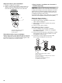
Non-vented (recirculating) Roof Venting
A. Deflector
B. 6" (15.2 cm) round vent
A. Roof cap
B. 6" (15.2 cm) round vent
Vent piece 6" (15.2 cm) round
45° elbow 2.5 ft
(0.8 m)
90° elbow 5.0 ft
(1.5 m)
B
A
B
A
1 - 90° elbow = 5.0 ft (1.5 m)
1 - wall cap = 0.0 ft (0.0 m)
8 ft (2.4 m) straight = 8.0 ft (2.4 m)
System length = 13 ft (3.9 m)
90 elbow
6 ft (1.8 m)
2 ft
(0.6 m)
Wall cap

8
INSTALLATION INSTRUCTIONS
Prepare Location
■ It is recommended that the vent system be installed before
the range hood is installed.
■ Before making cutouts, make sure there is proper clearance
within the ceiling for exhaust vent.
■ Range hood is to be installed 24" (61.0 cm) min. for electric
cooking surfaces, 30" (76.2 cm) min. for gas cooking
surfaces, to a suggested maximum of 36" (91.4 cm) above
the cooking surface.
1. Disconnect power.
2. Determine which venting method to use: roof or non-vented.
3. Select a flat surface for assembling the range hood. Place
covering over that surface.
4. Using 2 or more people, lift range hood onto covered surface.
5. Remove the motor from the canopy assembly (see the “Motor
Removal” section in this section).
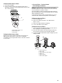
Motor Removal
To remove motor:
1. Remove the filter cover and metal grease filter (see the “Metal
Grease Filters” section in the Range Hood Care section).
2. Disconnect the blower motor wiring at the 9 pin connector.
3. Locate the special ½" (13 mm) tool inside the range hood
blower housing in the left front corner behind the insulation
pad. Use it to loosen the 4 nuts located inside the blower
housing that mounts the motor to the module top cover.
4. Grasp the motor plate and slide the motor toward the
back of the module housing to the large openings in
the keyhole slots.
5. Remove the motor from the range hood.
Range Hood Mounting Screws Installation
1. Determine and mark the centerline on the ceiling where the
range hood will be installed, considering the requirements for
ceiling support structures. See the “Location Requirements”
section. Make sure the range hood is centered over the
cooking surface.
2.
Tape template in place on the ceiling at the marked centerline.
Align the front of the template with the front of the cooktop.
3. Use a pencil to mark the mounting screws, wire access and
duct hole locations on the ceiling.
NOTE: Mounting hole locations must be into the ceiling
support structure. The mounting structure in the ceiling must
be able to support 100 lbs (45.4 kg).
Remove the template.
4. Drill (4) ³⁄₁₆" (4.8 mm) pilot holes at the marked locations on
the ceiling for installing the hanger bolts.
5. Using a T20
®
Torx
®
bit and driver, install the (4) 8 x 80 mm
hanger bolts into the pilot holes. Leave approximately ¾"
(2 cm) protruding down from the ceiling.
6. Screw the nuts on the hanger bolts, but do not tighten.
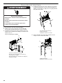
A. Special ½" (13 mm) tool
B. Motor assembly
C. Keyhole slots (large opening) (4)
D. ½" (13 mm) motor mounting nuts (4)
E. Motor plate
F. Module top cover
WARNING
Excessive Weight Hazard
Use two or more people to move and install
range hood.
Failure to do so can result in back or other injury.
B
F
E
D
C
A
A. Blower housing
B. Keyhole slots (4)
C. Motor assembly
D. Motor plate
A
B
D
C
³⁄₄"
(2 cm)

9
Complete Preparation
For Vented installations only:
1. Determine and make all necessary cuts in the ceiling for
the vent system. Install the vent system before installing
the hood. See “Venting Requirements” section.
2. Using a jigsaw or keyhole saw , cut a 6½" (16.5 cm) diameter
hole in the ceiling for the vent duct.
3. Install the vent duct through the hole in the ceiling.
4. Connect the flexible vent section to the vent system.
NOTE: Mounting boss handle must be parallel with the front
of the range hood to align the mounting studs with the half
slots in the module top cover plate.
For Vented and Non-Vented installations:
1. Expand the flexible section of vent duct (supplied) to
approximately 12" (30.5 cm) to 24" (61.0 cm) depending
on the ceiling height.
NOTE: For ceiling heights above 9' (2.7 m), additional 6"
(15.2 cm) round duct (not supplied) will be required.
2. Loosen the four nuts on the mounting boss. (The back flange
of each nut should be approximately ³⁄₁₆" [5 mm] from the
face of the mounting boss.)
3. Secure all connections with vent clamps.
4. Determine the required location in the ceiling for the
home power supply cable and drill a 1¼" (3.2 cm) hole
at this location.
Top View:
Use flexible wiring. Crosshatch is the open area available for
wiring access in the ceiling within the upper chimney area.
5. Run the home power supply cable according to the National
Electrical Code or CSA Standards and local codes and
ordinances. There must be enough flexible wiring from the
fused disconnect (or circuit breaker) box to make the
connection in the hood’s electrical terminal box.
NOTE: Do not reconnect power until installation is complete.
6. Use caulk to seal all openings.
Install Range Hood
1. Slip the upper chimney cover over the assembled vent duct
and electrical outlet and slide it to the ceiling. Align the large
end of the keyhole slots in the top of the upper chimney cover
up over the nuts and then slide it into the smaller slot section
on the keyhole slots.
2. Using the ½" (13 mm) special tool (supplied) or a ½" (13 mm)
socket and driver with 24" of extensions, tighten the nuts to
fasten the upper chimney cover section to the ceiling.
A. 6" (15.2 cm) flexible metal duct
B. Mounting boss
C. Mounting boss handle
D. Mounting studs and nuts (4)
E.
³⁄₁₆
" (5 mm)
F. Ve nt c lam p
G. 6" (15.2 cm) round vent
system duct
A
B
C
D
E
F
G
Vented Installation: Non-vented (recirculating)
Installation:
A. 1
¹¹⁄₁₆
" (4.3 cm)
B. 1
¹³⁄₁₆
" (4.8 cm)
C. 9
⁷⁄₈
" (24.9 cm)
D.
⁵⁄₈
" (1.5 cm)
E. Electrical box
F. Front of range hood
G. 6" (15.2 cm) round duct
A. 7" (17.8 cm)
B. 1½" (3.8 cm)
C.
⁵⁄₈
" (1.5 cm)
D. Air deflector
E. Electrical box
F. Front of range hood
A
B
C
D
F
E
G
A
B
C
D
F
E

10
3. Locate and remove the (2) 4 x 13 mm service screws inside
the range hood blower housing.
NOTE: These are be used to hold the lower chimney cover
up while assembling the range hood canopy to the upper
chimney cover.
4. Slide the lower chimney cover up over the upper chimney
cover until its bottom edge is above the holes on the upper
chimney cover front and back. While holding the lower
chimney cover, install the 4 x 13 mm service screws in
each side of the upper chimney cover. Leave approximately
¹⁄₈" (3 mm) between the head of the screw and the upper
chimney cover. Lower the lower chimney cover to rest on the
top of the screws. These screws will hold the lower chimney
cover up while assembling the range hood canopy to the
upper chimney cover.
5. Move the range hood to its mounting location and
connect the power supply. See the “Make Electrical
Connections” section.
6. Lift the range hood canopy into the approximate
recommended height for the cooktop type and install a
minimum of (4) 5 x 12 mm screws (D) (2 each side) through
the slots in the upper chimney cover and into the mounted
threaded fasteners (F) of the range hood canopy.
7. Adjust the range hood to the desired height. Level the
range hood and tighten the screws using a T20
®
Torx
®
bit.
See “Installation Dimensions” in the “Location Requirements”
section.
NOTE: Final height must be between the recommended
minimum and maximum dimension. The mounted threaded
fasteners (F) are for height adjustments during installation for
approved minimum and maximum distance between the
bottom of the range hood and the top of the cooking surface.
8. Reach inside the range hood cavity and grasp the handle of
the mounting boss. Pull down to align nuts through cutout
holes in the module top cover. Push back into half-slots to
assemble. Tighten (4) nuts using the ½" (13 mm) special tool
or ½" socket and driver with extension.
A. 4 x 13 mm service screws (2)
B. Inside area of range hood blower housing
A. Lower chimney cover (front)
B. Bottom edge of lower chimney cover
C. 4 x 13 mm screws
D. Upper chimney cover
A. Lower chimney cover
B. 4 x 13 mm screws
C. Upper chimney cover
D.
¹⁄₈
" (3.2 mm)
A
B
A
D
C
B
B
A
C
D
A. Ceiling
B. Lower chimney cover
C. Upper chimney cover
D. Mounting screws (4)
E. Range hood canopy
assembly
F. Range hood canopy
mounted thread fasteners
B
A
C
D
E
F

11
9. Push up and hold the lower chimney cover, and remove the
(2) 4 x 13 mm screws. Slide the lower chimney cover down
onto the top of the range hood canopy.
10. Replace (2) 4 x 13 mm service screws into storage area
inside range hood blower housing.
11. Go to “Complete Installation” section.
Make Electrical Connection
1. Disconnect power.
2. Remove the (2) screws from the top of the electrical box
cover and set the screws and cover aside.
3. Using a T20
®
Torx
®
driver, remove the (4) screws from the wire
protector race panel and set the part and screws aside.
Do not damage the wiring.
4. Using a T20
®
Torx
®
driver, remove the (2) screws inside the
electrical box holding the module plate and the (6) other
screws around the perimeter of the module plate.
A. Lower chimney cover
B. 4 x 13 mm screw (2)
C. Upper chimney cover
D. Range hood canopy assembly
A. 4 x 13 mm service screws (2)
B. Inside area of range hood blower housing
C
A
D
B
A
B
WARNING
Electrical Shock Hazard
Disconnect power before servicing.
Replace all parts and panels before operating.
Failure to do so can result in death or electrical shock.
A. Electrical box cover
B. Screws - electrical box cover (2)
C. Wire protector race
D. Screws - wire protector race (4)
E. Electrical wiring
A. Screws - module top assembly (8)
B. Module plate assembly
C. Range hood module
A
B
C
D
E
A
B
C

12
5. Lift module plate assembly from top of range hood module
and position it to rest on top of the module.
6. Using a T20
®
Torx
®
driver, remove (2) screws from the
electrical connection box on the bottom of the module
plate assembly.
7. Remove knockout labeled “Elec IN” from the module top
plate, and install UL listed or CSA approved strain relief.
8. Run the flexible 3 wire home power supply cable from
the ceiling through the strain relief and into the electrical
connection box.
9. Use UL listed wire connectors and connect the
black wires together.
10. Use UL listed wire connectors and connect the
white wires together.
11. Connect the green (or bare) ground wire from the home
power supply cable to the green (or green/yellow) ground
wire in the electrical box using a UL listed wire connector.
12. Tighten strain relief to secure the home power supply cable.
13. Reassemble the electrical connection box cover
on the bottom of the module plate assembly.
14. Reassemble the module plate assembly to the top of the
range hood module and tighten the (8) assembly screws.
15. Reaassemble the electrical box cover and wire race to the
front of the range hood module.
A. Module plate assembly
B. Range hood module
A. Electrical connection box cover
B. Screws (2)
C. Electrical connection box
A. Bottom of module top plate
B. Elec IN knockout
A
B
C
A
B
A
B
A. UL listed or CSA approved
strain relief
B. 3-wire flexible home power
supply cable
C. Green, bare or yellow/green
wires
D. Black wires
E. White wires
F. UL listed wire connectors (3)
G. 3-wire flexible power cable
from electrical box
A
B
G
C
D
E
F
WARNING
Electrical Shock Hazard
Electrically ground blower.
Connect ground wire to green and yellow ground wire
in terminal box.
Failure to do so can result in death or electrical shock.

13
Complete Installation
Reinstall Motor:
1. Place the motor into the blower module housing positioning
it with the large keyholes in motor mounting plate towards
the back of the canopy.
2. Grasping the motor plate, push the motor up into the blower
module housing. Locate the large keyholes over the motor
mounting nuts, push up against the module top cover and
pull the motor forward to lock into the small keyholes slots.
3. Use the special ½" (13 mm) tool and tighten the (4) nuts to
secure the motor.
4. Reconnect 9 pin connector from motor to electrical power.
5. Reconnect power.
Complete Installation:
1. For non-vented (recirculating) installations only, install the
charcoal filters over the metal mesh filter. See the “Range
Hood Care” section.
2. Install metal filters. See the “Range Hood Care” section.
3. Check the operation of the range hood blower and light.
See the “Range Hood Use” section.
If range hood does not operate, check to see whether a
circuit breaker has tripped or a household fuse has blown.
NOTE: To get the most efficient use from your new range hood,
read the “Range Hood Use” section.
RANGE HOOD USE
The range hood is designed to remove smoke, cooking vapors
and odors from the cooktop area. For best results, start the
hood before cooking and allow it to operate several minutes
after the cooking is complete to clear all smoke and odors
from the kitchen.
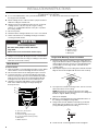
The range hood controls are located on the front of the canopy.
Control Panel
Controls and Features
NOTES:
■ To activate the controls, press and release the desired button.
■ The control feature button will be lit when a control feature
is turned On.
Sleep Mode
The range hood automatically enters Sleep Mode when not
in use. After 10 minutes of no range hood activity, all of the
control button lights will turn Off. To deactivate Sleep Mode,
press any button.
Auto Sense
Auto Sense allows the range hood fan to turn on automatically
when it senses heat higher than its allowable temperature limit.
When Auto Sense is On, the fan speed will increase or decrease
based on the temperature Auto Sense is measuring.
Auto Sense can be manually increased by pressing a higher fan
speed. The fan will run at the selected speed for 10 minutes
before returning to the speed selected for Auto Sense.
If Auto Sense is On, the Auto button light will turn Off and go into
Sleep Mode when the vent hood is not in use. If the vent hood is
turned On by the consumer or by Auto Sense, the Auto button
light will turn On.
To set Auto Sense:
Press AUTO.
To Select Auto Sense Cooktop Type:
NOTE: The range hood is factory-set for the gas
cooktop mode.
Press and hold AUTO for 5 seconds to switch between
the gas cooktop and electric cooktop modes.
The Auto button light will flash 5 times when the range hood
is changed to the electric cooktop mode. Auto Sense is now
set to work with electric cooktops and ranges.
The Auto button light will flash 3 times when the range hood
is changed to the gas cooktop mode. Auto Sense is now set
to work with gas cooktops and ranges.
Changing the cooktop type will change the temperature limit
for Auto Sense to turn On. When the range hood senses
a high enough temperature, the fan will start automatically.
When the temperature drops below the set temperature limit,
the fan will stop automatically. The Auto button light will turn
Off after the range hood enters Sleep Mode, but Auto Sense
is still active.
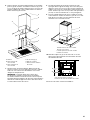
A. Louver holes (non-vented
[recirculating] installations only)
B. Chimney covers
C. Lamps
D. Filter door
E. Canopy
F. Co ntr ol p ane l
A
C
D
E
F
B
Auto Low
Med
Hi Boost Filter Light

14
To Deactivate Auto Sense:
If the Auto button is lit, press AUTO once to deactivate
Auto Sense. The Auto button light will turn Off.
If Auto Sense is in Sleep Mode, press AUTO once to
deactivate Sleep Mode and turn the Auto button light On.
Press AUTO again to deactivate Auto Sense and turn Off
the Auto button light.
Auto Sense will automatically turn off after 2 hours of no
activation of the Auto Sense system. To reset Auto Sense,
press AUTO.
Manual Vent Functions
Timer
The range hood can be set to automatically turn off
after 15 minutes.
1. Press and hold the desired fan speed button for 2 seconds.
The fan will run on the chosen speed for 15 minutes and the
fan speed button light will flash continuously.
After 15 minutes, the fan will turn Off automatically.
2. Press the desired fan speed button again while the fan timer
is running to cancel the fan timer.
NOTE: Changing the fan speed or turning Auto Sense On will
also cancel the 15-minute timer.
Filter
The Filter button lights up when it is time to replace or clean the
filter. The button will be lit only when the fan is On. Press FILTER
after replacing the filter to turn the Filter button light Off. See the
“Cleaning” section for how to replace or clean the filter.
Light
Press LIGHT to turn the range hood lights On and Off.
RANGE HOOD CARE
Cleaning
IMPORTANT: Clean the hood and grease filters frequently
according to the following instructions. Replace grease filters
before operating hood.
Exterior Surfaces:
To avoid damage to the exterior surface, do not use steel wool or
soap-filled scouring pads.
Always wipe dry to avoid water marks.
Cleaning Method:
■ Liquid detergent soap and water, or all-purpose cleanser
■ Wipe with damp soft cloth or nonabrasive sponge, then rinse
with clean water and wipe dry.
Metal Grease Filters
The filter should be washed frequently. Place the metal filter in
the dishwasher or hot detergent solution to clean.
Let the filter dry thoroughly before replacing it.
NOTE: The metal grease filter is located behind the center metal
filter cover. The panel is magnetically secured along the front
and has a tab along the back to hold the filter cover in place.
To access the grease filter, grasp the panel on the front corners
and pull down. This releases the panel from the magnets and
allows the panel to swing down. Pull the alignment tab on the
filter cover out of the alignment slot on the range to remove.
Fan Speeds
Low Press LOW to turn the fan on at Low speed.
Med Press MED to turn the fan on at Medium
speed.
Hi Press HI to turn the fan on at High speed.
Boost Press BOOST to turn the fan on at the
highest speed. Boost will automatically turn
Off after 10 minutes and the fan will switch
to High speed.
A. Slot for filter cover alignment
B. Filter cover magnets
C. Filter cover
D. Tab on filter cover for alignment
A
B
C
D

15
To Remove Metal Grease Filters:
1. Turn off fan and lights.
2. Remove the filter holder frame and grease filter using a
flat-blade screwdriver to turn the grease filter release screws
90° counterclockwise.
To Replace Metal Grease Filter:
Replace grease filter and filter holder frame into range hood.
Align the grease filter release screw and use a flat-blade
screwdriver to turn the grease filter release screws 90° clockwise
to lock in place.
Charcoal Filters - For Non-Vented
(recirculating) Installations
NOTE: After approximately 3 years of use the charcoal filter
should be replaced. To order a replacement Charcoal Filter Kit,
see the “Assistance or Service” section.
The charcoal filters can be cleaned and reactivated. Clean the
filter in the dishwasher using normal detergent and choosing the
highest temperature setting.
To reactivate the filter, the filter should be dried in an oven for
10 minutes with a maximum temperature of 210°F (100°C).
To Remove Charcoal Filters:
1. Turn fan and lights off.
2. Remove the metal grease filters. See “Metal Grease
Filters” section.
3. Remove the upper and side lock springs.
4. Clean or discard the charcoal filter.
To Replace Charcoal Filters:
1. For non-vented (recirculating installations) install charcoal
filter, wrapping it around the grease filter.
2. Place the charcoal filter mat around the grease filter and
fix it in place by using the cap lock springs provided.
3. Position the upper cap and fix it in place using the cap lock
spring provided.
A. Grease filter release screw
B. Filter holder frame
C. Grease filter
C
B
A
A. Charcoal filter mat
B. Grease filter
C. Charcoal filter side lock springs
D. Upper cap
E. Cap lock spring
F. Grease filter support

16
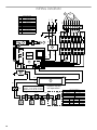
WIRING DIAGRAM
Additional lamp only
in 4 lamps version
Fuse
RL2
RL4
RL1
FT1
FT2
FT6 FT4
FT5FT3
L
N
1
BK
BK
BK
BK - 1
BK
BK
YL/
GN
YL/
GN
WH
WH
WH
WH - 2
YL
BR
BK - 3
BR
BR
BU
WH -
BU - 5
BU
BU
RD
RD - 4
RD
RD
GY
GY - 3
Motor Specifications
3.7 A
120 VAC
Blue - Red
Blue - Black
Frequency
Power Supply
Wattage Rating
14.90 Ohm
9.92 Ohm
22.00 Ohm
Amperage
Motor Speed/Resistance
18.40 Ohm
420 W
Blue - Gray
60 Hz
Blue - White
Component Layout
Description
Num.
E.M.I. Filter
User Interface
Main Board
Light Driver
Capacitor
LED Lamp
6
5
4
3
2
1
L
N
C
1
3
2
4
Temperature Sensor
Surge Protector
Motor
9
8
7
BK
YL/
GN
WH
YL
BR
BU
RD
GY
BK
YL/
GN
WH
YL
BR
BU
RD
GY
BK
BU
RD
BU
2 Speed
4 Speed
3 Speed
1 Speed
120 VAC
120 VAC
120 VAC
120 VAC
120 VAC
Not
used
Not
used
12 VDC
12 VDC12 VDC
12 VDC
12 VDC
BK
YL/
GN
WH
YL
BR
BU
RD
GY
SEL0099388
23
1
23
1
4
23
1
4
1
2
3
4
5
6
7
8
M
9
6 66
23
1
4 23
1
4

17
ASSISTANCE OR SERVICE
If you need service:
Please refer to the warranty page in this manual.
If you need replacement parts:
If you need to order replacement parts, we recommend that
you use only factory specified parts. Factory specified parts
will fit right and work right because they are made with the
same precision used to build every new appliance.
To locate factory specified replacement parts in your area, call
the following customer assistance telephone number or your
nearest designated service center.
In the U.S.A.
Call Jenn-Air Customer eXperience Center toll free:
1-800-JENNAIR (1-800-536-6247) or visit our website at
www.jennair.com.
Our consultants provide assistance with:
■ Scheduling of service. Jenn-Air
®
appliances designated
service technicians are trained to fulfill the product
warranty and provide after-warranty service anywhere
in the United States.
■ Features and specifications on our full line of appliances.
■ Referrals to local Jenn-Air
®
appliance dealers.
■ Installation information.
■ Use and maintenance procedures.
■ Accessory and repair parts sales.
■ Specialized customer assistance (Spanish speaking,
hearing impaired, limited vision, etc.).
For further assistance:
If you need further assistance, you can write to Jenn-Air
®
Appliances with any questions or concerns at:
Jenn-Air Brand Home Appliances
Customer eXperience Center
553 Benson Road
Benton Harbor, MI 49022-2692
Please include a daytime phone number in your correspondence.
In Canada
Call the Whirlpool Canada LP Customer eXperience Centre toll
free at 1-800-JENNAIR (1-800-536-6247) or visit our website at
www.jennair.ca.
Our consultants provide assistance with:
■ Scheduling of service. Jenn-Air
®
appliances designated
service technicians are trained to fulfill the product warranty
and provide after-warranty service anywhere in Canada.
■ Features and specifications on our full line of appliances.
■ Referrals to local Jenn-Air
®
appliance dealers.
■ Installation information.
■ Use and maintenance procedures.
■ Accessory and repair parts sales.
For further assistance:
If you need further assistance, you can write to Jenn-Air
®
Appliances with any questions or concerns at:
Jenn-Air Brand Home Appliances
Customer eXperience Centre
200 - 6750 Century Ave.
Mississauga, Ontario L5N 0B7
Please include a daytime phone number in your correspondence.
Accessories
Charcoal Filter Kit
(for non-vented installations only)
Order Part Number W10272069
Chimney Kit Recirculation
(for 7' 9" [2.36 m] to 9' 8" [2.95 m] ceilings)
(for non-vented installations only)
Order Part Number W10646865
Chimney Extension Kit - (vented)
(for 10' 2" [3.1 m] to 12' [3.66 m] ceilings)
Order Part Number W10646863
Chimney Extension Kit - (vented)
(for 9' 1" [2.77 m] to 11' [3.35 m] ceilings)
Order Part Number W10685946
Chimney Extension Kit - (recirculating)
(for 10' 2" [3.1 m] to 12' [3.66 m] ceilings)
(for non-vented installations)
Order Part Number W10685947
Chimney Extension Kit - (recirculating)
(for 9' 1" [2.77 m] to 11' [3.35 m] ceilings)
(for non-vented installations)
Order Part Number W10646866
6" (15.2 cm) Makeup Air Kit
(consult local building codes)
Order Part Number W10446915
Vent Duct Adapter 6" to 8" (15.2 cm to 20.3 cm)
(for 8" [20.3 cm] duct installations)
Order Part Number W10685950

18
12/14
JENN-AIR
®
MAJOR APPLIANCE
LIMITED WARRANTY
ATTACH YOUR RECEIPT HERE. PROOF OF PURCHASE IS REQUIRED
TO OBTAIN WARRANTY SERVICE.
Please have the following information available when you call the
Customer eXperience Center:
■ Name, address and telephone number
■ Model number and serial number
■ A clear, detailed description of the problem
■ Proof of purchase including dealer or retailer name and address
IF YOU NEED SERVICE:
1. Before contacting us to arrange service, please determine whether your product requires repair. Some
questions can be addressed without service. Please take a few minutes to review the Troubleshooting or
Problem Solver section of the Use and Care Guide, scan the QR code on the right to access additional
resources, or visit https://jennair.custhelp.com.
2. All warranty service is provided exclusively by our authorized Jenn-Air Service Providers
. In the U.S. and
Canada, direct all requests for warranty service to:
Jenn-Air Customer eXperience Center
1-800-JENNAIR (1-800-536-6247)
If outside the 50 United States or Canada, contact your authorized Jenn-Air dealer to determine whether another warranty applies.
https://jennair.custhelp.com
TWO YEAR LIMITED WARRANTY
WHAT IS COVERED WHAT IS NOT COVERED
For two years from the date of purchase, when this
major appliance is installed, operated and maintained
according to instructions attached to or furnished with
the product, Jenn-Air brand of Whirlpool Corporation or
Whirlpool Canada LP (hereafter “Jenn-Air”) will pay for
Factory Specified Replacement Parts and repair labor
to correct defects in materials or workmanship that
existed when this major appliance was purchased, or at
its sole discretion replace the product. In the event of
product replacement, your appliance will be warranted
for the remaining term of the original unit's warranty
period.
YOUR SOLE AND EXCLUSIVE REMEDY UNDER THIS
LIMITED WARRANTY SHALL BE PRODUCT REPAIR
AS PROVIDED HEREIN. Service must be provided by a
Jenn-Air designated service company. This limited
warranty is valid only in the United States or Canada
and applies only when the major appliance is used in
the country in which it was purchased. This limited
warranty is effective from the date of original consumer
purchase. Proof of original purchase date is required to
obtain service under this limited warranty.
1. Commercial, non-residential, multiple-family use, or use inconsistent with published
user, operator or installation instructions.
2. In-home instruction on how to use your product.
3. Service to correct improper product maintenance or installation, installation not in
accordance with electrical or plumbing codes or correction of household electrical or
plumbing (i.e. house wiring, fuses or water inlet hoses).
4. Consumable parts (i.e. light bulbs, batteries, air or water filters, preservation
solutions, etc.).
5. Defects or damage caused by the use of non-genuine Jenn-Air parts or accessories.
6. Conversion of products from natural gas or L.P. gas.
7. Damage from accident, misuse, abuse, fire, floods, acts of God or use with products
not approved by Jenn-Air.
8. Repairs to parts or systems to correct product damage or defects caused by
unauthorized service, alteration or modification of the appliance.
9. Cosmetic damage including scratches, dents, chips, and other damage to the
appliance finishes unless such damage results from defects in materials and
workmanship and is reported to Jenn-Air within 30 days.
10. Discoloration, rust or oxidation of surfaces resulting from caustic or corrosive
environments including but not limited to high salt concentrations, high moisture or
humidity or exposure to chemicals.
11. Food or medicine loss due to product failure.
12. Pick-up or delivery. This product is intended for in-home repair.
13. Travel or transportation expenses for service in remote locations where an authorized
Jenn-Air servicer is not available.
14. Removal or reinstallation of inaccessible appliances or built-in fixtures (i.e. trim,
decorative panels, flooring, cabinetry, islands, countertops, drywall, etc.) that
interfere with servicing, removal or replacement of the product.
15. Service or parts for appliances with original model/serial numbers removed, altered
or not easily determined.
The cost of repair or replacement under these excluded circumstances shall be
borne by the customer.
DISCLAIMER OF IMPLIED WARRANTIES
IMPLIED WARRANTIES, INCLUDING ANY IMPLIED WARRANTY OF MERCHANTABILITY OR IMPLIED WARRANTY OF FITNESS FOR A
PARTICULAR PURPOSE, ARE LIMITED TO ONE YEAR OR THE SHORTEST PERIOD ALLOWED BY LAW. Some states and provinces do not allow
limitations on the duration of implied warranties of merchantability or fitness, so this limitation may not apply to you. This warranty gives you
specific legal rights, and you also may have other rights that vary from state to state or province to province.
DISCLAIMER OF REPRESENTATIONS OUTSIDE OF WARRANTY
Jenn-Air makes no representations about the quality, durability, or need for service or repair of this major appliance other than the representations
contained in this warranty. If you want a longer or more comprehensive warranty than the limited warranty that comes with this major appliance,
you should ask Jenn-Air or your retailer about buying an extended warranty.
LIMITATION OF REMEDIES; EXCLUSION OF INCIDENTAL AND CONSEQUENTIAL DAMAGES
YOUR SOLE AND EXCLUSIVE REMEDY UNDER THIS LIMITED WARRANTY SHALL BE PRODUCT REPAIR AS PROVIDED HEREIN. JENN-AIR
SHALL NOT BE LIABLE FOR INCIDENTAL OR CONSEQUENTIAL DAMAGES. Some states and provinces do not allow the exclusion or limitation
of incidental or consequential damages, so these limitations and exclusions may not apply to you. This warranty gives you specific legal rights, and
you also may have other rights that vary from state to state or province to province.

19
SÉCURITÉ DE LA HOTTE DE CUISINIÈRE
Risque possible de décès ou de blessure grave si vous ne
suivez pas immédiatement les instructions.
Risque possible de décès ou de blessure grave si vous
ne suivez pas les instructions.
Tous les messages de sécurité vous diront quel est le danger potentiel et vous disent comment réduire le risque de blessure et
ce qui peut se produire en cas de non-respect des instructions.
Votre sécurité et celle des autres est très importante.
Nous donnons de nombreux messages de sécurité importants dans ce manuel et sur votre appareil ménager. Assurez-vous de
toujours lire tous les messages de sécurité et de vous y conformer.
AVERTISSEMENT
DANGER
Voici le symbole d’alerte de sécurité.
Ce symbole d’alerte de sécurité vous signale les dangers potentiels de décès et de blessures graves à vous
et à d’autres.
Tous les messages de sécurité suivront le symbole d’alerte de sécurité et le mot “DANGER” ou
“AVERTISSEMENT”. Ces mots signifient :
Avertissements de la proposition 65 de l'État de Californie :
AVERTISSEMENT : Ce produit contient au moins un produit chimique connu par l’État de Californie pour être à l’origine de
cancers.
AVERTISSEMENT : Ce produit contient au moins un produit chimique connu par l’État de Californie pour être à l’origine de
malformations et autres déficiences de naissance.

20
IMPORTANTES INSTRUCTIONS DE SÉCURITÉ
LIRE ET CONSERVER CES INSTRUCTIONS
AVERTISSEMENT : POUR RÉDUIRE LE RISQUE
D'INCENDIE, CHOC ÉLECTRIQUE OU DOMMAGES
CORPORELS, RESPECTER LES INSTRUCTIONS
SUIVANTES :
■ Utiliser cet appareil uniquement dans les applications
envisagées par le fabricant. Pour toute question, contacter
le fabricant.
■ Avant d'entreprendre un travail d'entretien ou de nettoyage,
interrompre l'alimentation de la hotte au niveau du tableau
de disjoncteurs, et verrouiller le tableau de disjoncteurs
pour empêcher tout rétablissement accidentel de
l'alimentation du circuit. Lorsqu'il n'est pas possible de
verrouiller le tableau de disjoncteurs, placer sur le tableau
de disjoncteurs une étiquette d'avertissement proéminente
interdisant le rétablissement de l'alimentation.
■ Tout travail d'installation ou câblage électrique doit être
réalisé par une personne qualifiée, dans le respect des
prescriptions de tous les codes et normes applicables, y
compris les codes du bâtiment et de protection contre les
incendies.
■ Ne pas faire fonctionner un ventilateur dont le cordon ou la
fiche est endommagé(e). Jeter le ventilateur ou le retourner
à un centre de service agréé pour examen et/ou réparation.
■ Une source d'air de débit suffisant est nécessaire pour le
fonctionnement correct de tout appareil à gaz (combustion
et évacuation des gaz à combustion par la cheminée), pour
qu'il n'y ait pas de reflux des gaz de combustion. Respecter
les directives du fabricant de l'équipement de chauffage et
les prescriptions des normes de sécurité - comme celles
publiées par la National Fire Protection Association (NFPA)
et l'American Society for Heating, Refrigeration and Air
Conditioning Engineers (ASHRAE), et les prescriptions des
autorités réglementaires locales.
■ Lors des opérations de découpage et de perçage dans un
mur ou un plafond, ne pas endommager les câblages
électriques et les canalisations qui peuvent s’y trouver.
■ Les ventilateurs d'évacuation doivent toujours décharger
l'air à l'extérieur.
MISE EN GARDE : Cet appareil est conçu uniquement
pour la ventilation générale. Ne pas l'utiliser pour l'extraction
de matières ou vapeurs dangereuses ou explosives.
MISE EN GARDE : Pour minimiser le risque d'incendie
et évacuer adéquatement les gaz, veiller à acheminer l'air
aspiré par un conduit jusqu'à l'extérieur - ne pas décharger
l'air aspiré dans un espace vide du bâtiment comme une
cavité murale, un plafond, un grenier, un vide sanitaire ou
un garage.
AVERTISSEMENT : POUR RÉDUIRE LE RISQUE
D'INCENDIE, UTILISER UNIQUEMENT DES CONDUITS
MÉTALLIQUES.
AVERTISSEMENT : POUR MINIMISER LE RISQUE
D'UN FEU DE GRAISSE SUR LA CUISINIÈRE :
■ Ne jamais laisser un élément de surface fonctionner à
puissance de chauffage maximale sans surveillance. Un
renversement/débordement de matière graisseuse pourrait
provoquer une inflammation et la génération de fumée.
Utiliser une puissance de chauffage moyenne ou basse
pour le chauffage d'huile.
■ Veiller à toujours faire fonctionner le ventilateur de la hotte
lors de la cuisson avec une puissance de chauffage élevée
ou lors de la cuisson d'un mets à flamber (à savoir crêpes
Suzette, cerise jubilée, steak au poivre flambé).
■ Nettoyer fréquemment les ventilateurs d'extraction. Veiller à
ne pas laisser la graisse s'accumuler sur les surfaces du
ventilateur ou des filtres.
■ Utiliser toujours un ustensile de taille appropriée. Utiliser
toujours un ustensile adapté à la taille de l'élément
chauffant.
AVERTISSEMENT : POUR RÉDUIRE LE RISQUE DE
DOMMAGES CORPORELS APRÈS LE DÉCLENCHEMENT
D'UN FEU DE GRAISSE SUR LA CUISINIÈRE, APPLIQUER
LES RECOMMANDATIONS SUIVANTES :
a
■ Placer sur le récipient un couvercle bien ajusté, une tôle à
biscuits ou un plateau métallique POUR ÉTOUFFER LES
FLAMMES, puis éteindre le brûleur. VEILLER À ÉVITER
LES BRÛLURES. Si les flammes ne s'éteignent pas
immédiatement, ÉVACUER LA PIÈCE ET APPELER LES
POMPIERS.
■ NE JAMAIS PRENDRE EN MAIN UN RÉCIPIENT
ENFLAMMÉ - vous risquez de vous brûler.
■ NE PAS UTILISER D'EAU, ni un torchon humide - ceci
pourrait provoquer une explosion de vapeur brûlante.
■ Utiliser un extincteur SEULEMENT si :
– Il s'agit d'un extincteur de classe ABC, dont on connaît le
fonctionnement.
– Il s'agit d'un petit feu encore limité à l'endroit où il s'est
déclaré.
– Les pompiers ont été contactés.
– Il est possible de garder le dos orienté vers une sortie
pendant l'opération de lutte contre le feu.
a
Recommandations tirées des conseils de sécurité en cas
d'incendie de cuisine publiés par la NFPA.
■ AVERTISSEMENT : Pour réduire le risque d'incendie
ou de choc électrique, ne pas utiliser ce ventilateur avec un
quelconque dispositif de réglage de la vitesse à semi-
conducteurs.
La page est en cours de chargement...
La page est en cours de chargement...
La page est en cours de chargement...
La page est en cours de chargement...
La page est en cours de chargement...
La page est en cours de chargement...
La page est en cours de chargement...
La page est en cours de chargement...
La page est en cours de chargement...
La page est en cours de chargement...
La page est en cours de chargement...
La page est en cours de chargement...
La page est en cours de chargement...
La page est en cours de chargement...
La page est en cours de chargement...
La page est en cours de chargement...
-
 1
1
-
 2
2
-
 3
3
-
 4
4
-
 5
5
-
 6
6
-
 7
7
-
 8
8
-
 9
9
-
 10
10
-
 11
11
-
 12
12
-
 13
13
-
 14
14
-
 15
15
-
 16
16
-
 17
17
-
 18
18
-
 19
19
-
 20
20
-
 21
21
-
 22
22
-
 23
23
-
 24
24
-
 25
25
-
 26
26
-
 27
27
-
 28
28
-
 29
29
-
 30
30
-
 31
31
-
 32
32
-
 33
33
-
 34
34
-
 35
35
-
 36
36


Jenn-Air JXI8742DS Manuel utilisateur
- Catégorie
- Hottes
- Taper
- Manuel utilisateur
- Ce manuel convient également à
dans d''autres langues
- English: Jenn-Air JXI8742DS User manual
Documents connexes
-
Jenn-Air JXI8936DS Manuel utilisateur
-
-
Jenn-Air JXI8042WS0 Le manuel du propriétaire
-
-
-
-
-
Jenn-Air JVW0636LS Manuel utilisateur
Autres documents
-
IKEA IH8432WS0 Guide d'installation
-
KitchenAid 36" Island-Mount Canopy Hood Manuel utilisateur
-
-
-
-
Whirlpool WVI75UC6DS Mode d'emploi
-
-
 Venmar Charcoal filter module Stainless Steel Guide d'installation
