Anolis ArcPixel™ Power Manuel utilisateur
- Catégorie
- Stroboscopes
- Taper
- Manuel utilisateur

Version 2.0

2
Table of contents
1. Important safety instructions ........................................................................................3
1. Consignes de sécurité importantes..............................................................................4
2. Operating determinations ..............................................................................................4
3. Description of the ArcPixel Power-US .......................................................................... 5
4. Installation.......................................................................................................................5
4.1. Connection to the mains: .......................................................................................... 5
4.2. Mounting the ArcPixel Power-US .............................................................................. 6
4.3. Connecting ArcPixes-US ........................................................................................... 6
4.4. Connecting ArcDots-US / ArcSource Out 4MC Pixel -US/ArcDotFlash-US .............. 9
6. Control menu map ........................................................................................................14
5. ArcPixel Power-US - DMX protocol ............................................................................. 11
7.Control menu .................................................................................................................16
7.1 DMX Addr (Fixture addressing) ............................................................................. 16
7.2 Info (Fixture information) ....................................................................................... 16
7.3 Dots (ArcDot/ArcPix settings) .............................................................................. 17
7.4 Personality ............................................................................................................... 18
7.5 Test ........................................................................................................................... 18
7.6 Stand-alone ............................................................................................................. 18
7.7 Special settings ........................................................................................................ 19
8. Software update............................................................................................................19
9. Incorporation of new dots (after replacing faulty dots) ........................................... 20
10. ArcPixel Power Web manager .................................................................................. 23
11.Technical Specications ............................................................................................. 25
ArcPixel Power-US

3
CAUTION!
Unplug mains lead before opening the housing!
FOR YOUR OWN SAFETY, PLEASE READ THIS USER MANUAL CAREFULLY
BEFORE YOU INITIAL START - UP!
ATTENTION!
Débrancher l’appareil avant d'ouvrir le boîtier!
POUR VOTRE SÉCURITÉ, LISEZ ATTENTIVEMENT CETTE NOTICE AVANT LA PRE-
MIERE UTILISATION
1. Important safety instructions
Every person involved with installation and maintenance of this product has to:
- be qualiled
- follow the instructions and heed all warnings in this manual
CAUTION!
Be careful with your operations. With a high voltage you can suer
a dangerous electric shock when touching the wires inside the unit!
This product has left our premises in absolutely perfect condition. In order to maintain this condition and to
ensure a safe operation, it is absolutely necessary for the user to follow the safety instructions and warning
notes written in this manual.
WARNING
To prevent injury, this apparatus must be securely installed in accordance with the
installation instructions.”
Do not block any ventilation openings. Install in accordance with the manufacturer’s instructions.
Do not install near any heat sources such as radiators, heat registers, stoves, or other apparatus (including
ampliers) that produce heat.
Do not use this apparatus near water. Clean only with dry cloth.
Only use attachments/accessories specied by the manufacturer.
Protect the power cord from being walked on or pinched particularly at plugs, convenience receptacles, and
the point where they exit from the apparatus.
Refer all servicing to qualied service personnel. Servicing is required when the apparatus has been damaged
in any way, such as power-supply cord or plug is damaged, liquid has been spilled or objects have fallen into the
apparatus, the apparatus has been exposed to rain or moisture, does not operate normally, or has been dropped.
Use a source of AC power that complies with local building and electrical rules. AC power has to have both
overload and short circuit protection.
This device falls under protection class I.Therefore the ArcPixel Power-US has to be
connected to a mains socket outlet with a protective earthing connection!
This device is for professional use only. It is not for household use.
Warning: Operation of this equipment in a residential environment could cause
radio interference.
Resistance of the equipment is designed for electromagnetic environments E1, E2, E3 according to the stand-
ard EN55103-2 ed.2 Electromagnetic compatibility. Product family standard for audio, video, audiovisual and
entertainment lighting control apparatus for professional use. Part 2: Immunity.
The installation company should measure levels of possible interferences above the tested levels
E1,E2,E3 given by this standard (e.g. transmitters in surrounding area) before installing the equipment.

4
Emission of the equipment complies with the standard EN55032 Electromagnetic compatibility
of multimedia equipment – Emission Requirements according to class A.
1. Consignes de sécurité importantes
Toute personne impliquée dans l'installation et la maintenance de ce produit doit:
- Être susamment qualié
- Suivre les instructions de ce manuel
ATTENTION!
Soyez prudent avec vos manipulations. Avec une haute tension, vous risquez un
choc électrique en touchant les ls à l'intérieur de l'appareil!
Ce produit a quitté nos ateliers dans un état irréprochable. An de maintenir cet état et pour assurer un bon
fonctionnement, il est absolument nécessaire de suivre les consignes de sécurité et les notes contenues dans
ce manuel.
AVERTISSEMENT
Pour éviter toute blessure, cet appareil doit être solidement xé à en conformité
avec les instructions d'installation. "
Ne pas bloquer les ouvertures de ventilation. Installer conformément aux instructions du fabricant.
Ne pas installer près de sources de chaleur telles que radiateurs, ou autres appareils (y compris les ampli-
cateurs) produisant de la chaleur.
Ne pas utiliser cet appareil près de l'eau. Nettoyer avec un chion sec.
Une prise de branchement ou un coupleur est utilisé comme dispositif de déconnexion, ce dispositif doit rester
facilement accessible.
N'utilisez que des accessoires spéciés par le fabricant.
Protégez le cordon d'alimentation du piétinement ou pincement, particulièrement au niveau des ches, des
prises, et le point où ils sortent de l'appareil
Conez toute réparation à un personnel qualié. Une réparation est nécessaire lorsque l'appareil a été endo-
mmagé de quelque façon que ce soit. cordon d'alimentation, che est endommagé, liquide renversé a l interieur,
ou des objets sont tombés dans l'appareil, l'appareil a été exposé à la pluie ou à l'humidité, ne fonctionne pas
normalement , ou s'il est tombé.
Utilisez une source de courant alternatif qui est conforme a l’endroit ou vous vous trouvez. La source alternative
doit avoir à la fois une protection de surcharge et de court-circuit.
Ce dispositif relève de la classe de protection I. Par conséquent, la ArcPixel Power-
-US doit être connecté à une prise électrique reliée à la terre!
2. Operating determinations
This product was designed for indoor use only.
If the unit has been exposed to drastic temperature uctuation (e.g. after transportation), do not switch it on
immediately. The arising condensation water might damage your unit. Leave the unit switched o until it has
reached room temperature.
Avoid brute force when installing or operating the unit.
When choosing the installation spot, please make sure that the unit is not exposed to extreme heat, moisture
or dust.
Only operate the unit after having checked that the housing is rmly closed and all screws are tightly fastened.

5
The maximum ambient temperature 40° C must never be exceeded.
Operate the unit only after having familiarized with its functions. Do not permit operation by persons not qualied
for operating the unit. Most damages are the result of unprofessional operation!
Please use the original packaging if the product is to be transported.
Please consider that unauthorized modications on the unit are forbidden due to safety reasons!
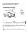
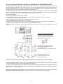
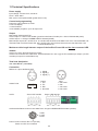
3. Description of the ArcPixel Power-US
4. Installation
CAUTION!
These servicing instructions are for use by qualied service personnel only. To
reduce the risk of electric shock do not perform any servicing other than that con-
tained in the operating instructions unless you are qualied to do so.
4.1. Connection to the mains:
The ArcPixel Power-US is equipped with auto-switching power supply that automatically adjusts to any 50-60Hz
AC power source from 100-240 Volts. The xture must be grounded.
Connect the xture to the mains with enclosed power cord.
This device falls under protection class I. Therefore the ArcPixel Power-US has
to be connected to a mains socket outlet with a protective earthing connection.
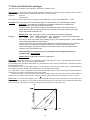
1 - Control board
2 - Power socket
3 - Ethernet
4 - DMX Output
5 - DMX Input
6 - ArcPix output 4
7 - ArcPix output 3
8 - ArcPix output 2
9 - ArcPix output 1
10 - ArcDot output 4
11 - ArcDot output 3
12 - ArcDot output 2
13 - ArcDot output 1

6
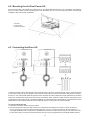
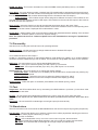
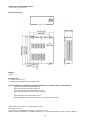
4.2. Mounting the ArcPixel Power-US
The ArcPixel Power-US should be be placed on a non-ammable at surface in any orientation and xed by
the four screws.There are four mounting holes of a dimension of 5x7 mm in housing of the driver. Ensure that
installation place is enough ventilated.
4.3. Connecting ArcPixes-US
1-Screws
2- at surface
3-mounting holes
Connect ArcPixes to the LED outputs of the ArcPixel Power-US (max. 65 ArcPixes per output). The rst ArcPix
in the ArcPix chain can be connected to the screw terminal board on the ArcPixel Power-US either via connec-
tion box or via customized cable length (has to be specied at order). Maximum length between the ArcPixel
Power-US and the last ArcPix must not exceed 100 metres. Max. number of LED modules connected to one
ArcPixel Power-US output is 65. For larger installation, the ArcPixel Power-US should be connected to the Robe
Media Server which allows automatic pixel mapping and full control of the ArcPixes modules.
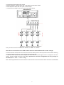
To connect ArcPixes-US
1. Disconnect ArcPixel Power-US from mains.
2. Connect ArcPixes to the ArcPixel Power-US. Connect the termination box ArcPix to each ArcPix line.
If you use Artnet for control of the ArcPixel Power-US, you can connect ArcPixes to all LED outputs 1-4.
For larger installation we recommend to set dierent universes for each ArcPix output. The rst ArcPix has
to have the bottom universe and the last ArcPix the top universe (requirement of the Robe Media Server).

7
3. Connect ArcPixel Power-US to mains
4. Run procedures " Search Dots" and " Sort Dots" from the menu "Dots"
5. Save adjusted values with the option "Store Cong".
7. Connect the ArcPixel Power-US to the Robe Media Server.
Every ArcPix line has to be terminated with the termination box ArcPix!
Note: Never connect/disconnect LED modules when the ArcPixelPower-US is under voltage!
If the line between ArcPixes is disconected, the ArcPixes behind point of interrupt will not work. Before restoring
connection between ArcPixes, switch o the ArcPixel Power-US.
In case that some ArcPix has been changed, the same address as had original ArcPix is assigned to the new
ArcPix by the ArcPixel Power-US. It is very important to save Dots conguration at every change of
ArcPixes.(Menu "Dots" -> "Store Cong"),
Max. cable length between the ArcPixel Power-US and the last connected ArcPix module should not exceed 100m

8
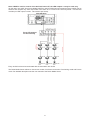
Note: If DMX is used for control of the ArcPixel Power-CE, the LED outputs 1-3 may be used only.
(In this case, one UART from four available UARTs is used for DMX input and remaining three UARTs can be
used for LED outputs only. LED output load is the same as in a case of the control by Artnet - max 65 LED
modules per LED output, but max. 195 modules per xture).
Every ArcPix line has to be terminated with the termination box ArcPix
The Robe Media Server allows to choose two modes of ArcPixes connection: Fixed-wiring mode and Picture
mode. For detailed description see the user manual of the Robin Media Server.
Three LED outputs
can be used only

9
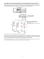
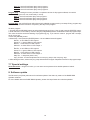
4.4. Connecting ArcDots-US / ArcSource Out 4MC Pixel -US/ArcDotFlash-US
Connect ArcDots to the LED output of the ArcPixel Power-US ( max. 16 ArcDots per output). Max. number of
all LED modules connected to the ArcPixel Power-US is 64 (but 48 ArcDotFlash-US only!). The ArcDots can
be interconnected directly or by using T- connectors - see the picture below. If you use Artnet for control of the
ArcPixel Power-US, you can connect ArcDots to all LED outputs 1-4.
For larger installation (more than 25 ArcDots), the ArcPixel Power-US should be connected to the Robe Media
Server which allows automatic pixel mapping and full control of the ArcDots modules. Without Robe Media
Server, you have to perform pixel mapping manually using the menu "Dots".
To connect ArcDots
1. Disconnect ArcPixel Power-US from mains.
2. Connect ArcDots to the ArcPixel Power-US. Connect active terminators to each ArcDots line.
3. Connect the ArcPixel Power-US to mains
4. Run procedures "Search Dots" and "Sort Dots" from the menu "Dots"
5. Save adjusted values with the option "Store Cong"
6. Disconnect the ArcPixel Power-US from mains and replace active terminators by passive terminators*.
7. Connect the ArcPixel Power-US to mains and to the Robe Media Server.
* Active terminators can remain permanent connected if there is place for them (they are bigger than passive
ones).
Note: Never connect/disconnect LED modules when the ArcPixelPower-US is under voltage!
If the line between ArcDots is disconected, the ArcDots behind point of interrupt will not work. Before restoring
connection between ArcDots, switch o the ArcPixel Power-US.
In case that some ArcDot has been changed, the same address as had original ArcDot is assigned to it by the
ArcPixel Power-US. It is very important to save ArcDots conguration at every change of an ArcDot.
(Menu "Dots" -> "Store Cong"),
Max. cable length between ArcPixel Power-US and the last connected ArcDot module should not be exceeded:
100m @ 16 ArcDots per LED output . Only one ArcDot can be connected to the T-connector.
Every ArcDot line has to
be terminated with the
passive terminator!
The minimum cable length of 0.3m
between two T-connectors has to
be kept in case that the pixel sor-
ting is executed manually from the
ArcPixel Power-US menu.
Exception for ArcDotFlashes-US:
Max. load per ArcPixel Power-US:
48 ArcDotFlashes-US
Max. load per output: 12 ArcDotFlashes-US

10
Note: If DMX is used for control of the ArcPixel Power-US, the LED outputs 1-3 may be used only.
(In this case, one UART from four available UARTs is used for DMX input and remaining three UARTs can be
used for LED outputs only. LED output load is the same as in a case of the control by Artnet - max 16 LED mo-
dules per LED output, but max. 48 modules per ArcPixel Power-US. For ArcDotFlashes-US is number reduced
to max 12 LED modules per LED output, but max. 36 modules per ArcPixel Power-US.)
Every ArcDot line has to be terminated with the passive terminator!
Note: the same rules as for the ArcDots-US go for the ArcSource Out 4MC Pixels-US and ArcDotFlashes-
-US with the following exception for the ArcDotFlashes-US: If no DMX signal is present at ArcPixel
Power-US, the ArcDotFlash modules ash randomly (22-28 ashes per minute).
The Robe Media Server allows to choose two modes of ArcDots connection: Fixed-wiring mode and Picture
mode. For detailed description see the user manual of the Robin Media Server.
Three LED outputs
can be used only
Exception for ArcDotFlashes-US:
Max. load per ArcPixel Power-US:
36 ArcDotFlashes-US
Max. load per output: 12 ArcDotFlashes-US

11
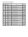
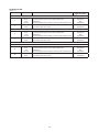
5. ArcPixel Power-US - DMX protocol
ArcDot-US/ ArcSource Outdoor 4MC Pixel -US
version 1.1
RGBW
mode=O
(Channel)
RGBW*
mode=On
(Channel)
Value Function
Type of
control
ArcDot 1/ ArcSource Outdoor 4MC Pixel 1
1 1
0-255
Red
Red LED saturation control (0-100%) proportional
2 2
0-255
Green
Green LED saturation control (0-100%) proportional
3 3
0-255
Blue
Blue LED saturation control (0-100%) proportional
- 4
0-255
White
White LED saturation control (0-100%) proportional
ArcDot 2/ ArcSource Outdoor 4MC Pixel 2
4 5
0-255
Red
Red LED saturation control (0-100%) proportional
5 6
0-255
Green
Green LED saturation control (0-100%) proportional
6 7
0-255
Blue
Blue LED saturation control (0-100%) proportional
- 8
0-255
White
White LED saturation control (0-100%) proportional
ArcDot 3/ ArcSource Outdoor 4MC Pixel 3
7 9
0-255
Red
Red LED saturation control (0-100%) proportional
8 10
0-255
Green
Green LED saturation control (0-100%) proportional
9 11
0-255
Blue
Blue LED saturation control (0-100%) proportional
- 12
0-255
White
White LED saturation control (0-100%) proportional
:
ArcDot 100/ ArcSource Outdoor 4MC Pixel 100
298 397
0-255
Red
Red LED saturation control (0-100%) proportional
299 398
0-255
Green
Green LED saturation control (0-100%) proportional
300 399
0-255
Blue
Blue LED saturation control (0-100%) proportional
- 400
0-255
White
White LED saturation control (0-100%) proportional
:
* RGBW modules only

12
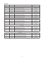
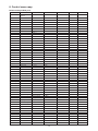
ArcPix-US
version 1.0
Channel
Value Function Type of control
ArcPix 1
1
0-255
Red
Red LED saturation control (0-100%) proportional
2
0-255
Green
Green LED saturation control (0-100%) proportional
3
0-255
Blue
Blue LED saturation control (0-100%) proportional
ArcPix 2
4
0-255
Red
Red LED saturation control (0-100%) proportional
5
0-255
Green
Green LED saturation control (0-100%) proportional
6
0-255
Blue
Blue LED saturation control (0-100%) proportional
ArcPix 3
7
0-255
Red
Red LED saturation control (0-100%) proportional
8
0-255
Green
Green LED saturation control (0-100%) proportional
9
0-255
Blue
Blue LED saturation control (0-100%) proportional
:
ArcPix 100
298
0-255
Red
Red LED saturation control (0-100%) proportional
299
0-255
Green
Green LED saturation control (0-100%) proportional
300
0-255
Blue
Blue LED saturation control (0-100%) proportional
:
ArcPix 170
508
0-255
Red
Red LED saturation control (0-100%) proportional
509
0-255
Green
Green LED saturation control (0-100%) proportional
510
0-255
Blue
Blue LED saturation control (0-100%) proportional

13
ArcDotFlash-US
version 1.1
Channel
Value Function
Type of control
ArcDotFlash 1
1
0-127
128
129-255
Strobe
Synchronous ashing from slow to fast (0.02Hz-20Hz)
Permanent lit
Random ashing from slow to fast (2.2 ashes/minute-28 ashes/minute)
proportional
step
proportional
2
0-255
Dimmer
Light intensity from 0% to 100%
proportional
ArcDotFlash 2
3
0-127
128
129-255
Strobe
Synchronous ashing from slow to fast (0.02Hz-20Hz)
Permanent lit
Random ashing from slow to fast (2.2 ashes/minute-28 ashes/minute)
proportional
step
proportional
4
0-255
Dimmer
Light intensity from 0% to 100%
proportional
:
ArcDotFlash 48
95
0-127
128
129-255
Strobe
Synchronous ashing from slow to fast (0.02Hz-20Hz)
Permanent lit
Random ashing from slow to fast (2.2 ashes/minute-28 ashes/minute)
proportional
step
proportional
96
0-255
Dimmer
Light intensity from 0% to 100%
proportional

14
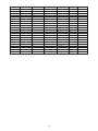
6. Control menu map
Default settings=Bold print
Level 1 Level 2 Level 3 Level 4 Level 5 Level 6 Level 7
DMX Addr Set DMX
Address
0001-0512
IP Address Default Address Set Address
Custom Address IP Adr 1 0-255
IP Adr 2 0-255
IP Adr 3 0-255
IP Adr 4 0-255
Set Address
Network mask Net M. 1
Net M. 2
Net M. 3
Net M. 4
Set Net M.
Info Software Version
IP Addr.
MAC Adr.
Dots New Dots
Unknown Dots
Dots Search Dots
Sort Dots Auto Sort
Manual Sort
Restore Last
Fade Time O
0.1s-25.5s
Dots Curve D. Curve 0-255
RGBW 4ch Mode On, O
Order Mode Order Compact
Order Universe
Store Cong
Test Dots
Update Dots No
Yes
Personality ArtNet Universe Uni. 1 0-255
Uni. 2 0-255
Uni. 3 0-255
Uni. 4 0-255
DMX Input Ethernet
Wired DMX
Display Settings Disp O Timer O, On
Display Lightnes 0-100%
Display Contrast 0-100%
Skip Cfg Mismatch Yes, No
Default Settings Set Defaults
Test
Single Dots
All Dots
Full Power
Stand Alone Play On Start O
Single
All
Full PWR
User P1

15
Level 1 Level 2 Level 3 Level 4 Level 5 Level 6 Level 7
User P2
User P3
Program Play User 1
User 2
User 3
Program Edit User 1
User 2
User 3 S.Count 1-35
Step 1 Red Z1 0-255
: Green Z1 0-255
Step 35 Blue Z1 0-255
White Z1 0-255
:
Red Z4 0-255
Green Z4 0-255
Blue Z4 0-255
White Z4 0-255
Step Tim. 0-25.5sec
Copy To Next
Special Settings Software Update No, Yes
Reset Password

16
7.Control menu
The control panel situated on the top cover of the ArcPixel Power-US allows xture addressing and set the
driver´s behaviour.
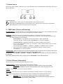
Control elements:
[ENTER] button- enters menu,conrms adjusted values and leaves menu.
, [UP] button and[DOWN] button- moves between menu items on the the same level, sets values.
[ESCAPE] button- leaves the menu without saving value.
7.1 DMX Addr (Fixture addressing)
Set DMX Address - use this menu item to set the DMX start address of the xture, which is dened as the rst
channel from which the ArcPixel Power-US will respond to the DMX controller.
IP address - select this menu item to set desired IP address. IP address is the Internet protocol
address.The IP uniquely identies any node (xture) on a network. There cannot be 2 xtures with
the same IP address on the network!
Default Address. This address is derived from xture´s MAC address and
cannot be changed. Conrm the item "Set Address" to select this address.
Custom Address. IP address consists of four decimal numbers, each ranging
from 0 to 255, separated by dots, e.g., 172.16.254.1. Each part represents a group of 8 bits
(octet) of the address.
The following items "IP Adr 1", " IP Adr 2", " IP Adr 3", " IP Adr 4" allow to set each
part (number) of the address. After setting desired IP address, conrm the item
"Set Address" to save this address.
Network mask - select this menu item to set desired network mask. A network mask is a 32-bit mask used to
divide an IP address into subnets and specify the networks available hosts.
The following items "Net M.1", "Net.M.2", " Net.M.3", " Net.M.4" serve for seting of each part (number) of
the net mask.
After setting desired network mask, conrm the item "Set Net M." to save adjusted values.
7.2 Info (Fixture information)
Use this menu to read useful information about the xture.
Software version - select this menu item to read software versions.
Dot 10.0/20 - Dot version. The items show software version of each LED module.
MA. In - Driver version. The item shows software version of the ArcPixel Pover-US.
IP Addr - this menu item shows the current IP address.
MAC Addr - select this menu item to read the MAC address (the MAC address "runs" on display).
Dots - select this menu item to read information about connected LED modules (ArcDot, ArcPix)
New Dots - the item shows the number of recently connected LED modules.
Unknown Dots - the item shows the number of LED modules which were not detected
by the dot checking procedure ("Search Dots") .

17
7.3 Dots (ArcDot/ArcPix settings)
Use this menu to prepare LED module for operation in desired matrix.
Search Dots - this function checks all LED modules connected to the xture and the message “Done” with the
number of found LED modules is displayed after nishing the procedure.
Example: Dots: 25
Search/Done
The ArcPixes, ArcDots are sorted according to their RDM UID in colour range RGB,RGB......RGB.
Sort Dots - this menu allows you to choose automatic or manual sorting of connected LED modules.
Auto Sort - Conected LED modules are sorted automatically by the following rule:
ArcPix modules are sorted according to their IDs.
ArcDot modules are sorted according to their distances from the ArcPixel Power-US
(the active terminator for the ArcDot has to be connected to the last ArcDot at each LED
output of the ArcPixel Power-US).
Manual Sort - after choosing this option, the following screen will be displayed:
Example: D001 St1 (D001..LEDE module No.1, St1... LED output 1 of the ArcPixel Power-US )
U1 A001 (U1........universe, A001.......DMX address)
You can go throw connected dots pressing the [UP] and [DOWN] buttons, current displayed
LED module starts blinking a white colour.
Press the [ENTER], item U1 starts to blink slowly. Now by means of the [UP] and [DOWN]
buttons you can move between the item A001 and U1. To edit celected item, press
the [ENTER] again, selected item will start to blink fast and you can set desired values
using the UP] and [DOWN] button.
After automatic or manual sorting, do not forget to save changes by means of
the menu item „Store Cong“.
Restore Last - recalls last saved dots conguration.
Fade Time - select this menu item to set a desired max. fade time (0-25.5 sec.). This adjusted fade time inu-
ences fade of RGB and dimmer during DMX operation:
If time between two receiving DMX values is > than fade time set in the item "Fade Time", the entire adjusted
fade time will be used.
If time between two receiving DMX values is < than fade time set in the item "Fade Time", the adjusted fade
time will be reduced to ll entire time between the two receiving DMX values.
e.g. "Fade Time".=2sec. and xture has received Red=0 DMX, after 5 seconds will receive Red=255 DMX. It
means, that red will go to full intensity during 2 seconds.
"Fade Time"=8 sec. and xture has received Red=0 DMX, after 5 seconds will receive Red=255 DMX. It
means, that red will go to full intensity during 5 seconds. (Max, fade time is reduced from 8 sec. to 5 sec.).
Dots Curve - this menu item allows you to select desired running of colour saturation. You can select 255
colour saturation runnings in all. The value 0 corresponds linear curve, the value 128 corresponds exponential
curve with index 1.9 and last value 255 corresponds exponential curve with index 2.6.

18
RGBW 4ch Mode - This function activates four channels RGBW mode (see DMX protocol) - for RGBW
modules only.
Order Mode - the menu allows to select a method how LED modules will be assigned to the Artnet Universe.
Order Compact - All LED modules will be assigned to the Universe at the rst LED output. After lling
this Universe, the rest of LED modules will be assigned to the Universe at the LED output 2.
Order Universe - LED modules output will be assigned to dierent Universes. LED modules on the
rst LED output to the Universe set at this LED output. LED modules on the second LED output to the Universe
set at the second LED output etc.
Store Cong - select this function to save all changes that have been done in the menu "Dots" .
Test Dots - use this menu item to browse throw the list of sorted LED modules.The ID of corresponding dot is
shown under the dot number. Displayed LED module blinks in white.
Update Dots - allows update of the connected LED modules after standard software updating of the ArcPixel
Power-US (item “Software Update” in the menu "Special Setting").
Note: The update via the menu "Software Update" has to be realized before running the "Update Dots"
procedure
7.4 Personality
Use this menu to modify the ArcPixel Power-US operating behavior.
ArtNet Universe - use the menu item to assign ArtNet universe to desired LED output.
Uni.1-ArtNet universe for LED output 1
:
Uni.4-ArtNet universe for LED output 4
Art-Net is a proprietary protocol for transmitting DMX512 (with RDM) over UDP/IP. Up to sixteen DMX512
universes can be accessed through one IP subnet.
The Universe is a single DMX 512 frame
of 512 channels.
DMX Input - this menu allows you to choose desired DMX data input:
Artnet - if this input is selected (RJ45), all LED outputs (1-4) are active.
Wired DMX - if this input is selected (3-pin XLR), only LED outputs 1-3 are active.
Display Settings - this menu allows you to change the display settings.
Display O Timer - if this item is on the display will be swiched o 2 minutes after last pressing any
button on the control panel.
Display Lightness - select this menu item to adjust the display intensity (0-100%).
Display Contrast- select this menu item to adjust contrast of the display (0-100%).
Default setting - select this option to set xture personalities to the default (factory) values.
7.5 Test
Single Dots - the LED modules blink one by one starting from DMX address 1 (universe 1) in the colour order
red, green, blue and white.
All Dots - all connected LED modules blink together in the colour order red, green, blue and white..
Before both test sequences, the "Search Dots" and "Sort Dots" procedures from the menu "Dots" have tu be
made.
Full Power - all connected LED modules light at max light output (R+G+B+W=full).
7.6 Stand-alone
The ArcPixel Power is not connected to the Robe Media Server but can execute pre-set programs (sequences).
Play On Start - This function allows you to select a program which will be played after switching the xture on.
Selected program will be played continuously in a loop.
O - function is disabled.
Single - LED modules blink one by one in the colour order red, green, blue and white.
All - all connected LED modules blink together in the colour order red, green, blue and white.
Full PWR - all connected LED modules light at max light output (R+G+B+W=full).

19
User P1 - the ArcPixel Power plays user program 1.
User P2 - the ArcPixel Power plays user program 2.
User P3 - the ArcPixel Power plays user program 3.
Program Play - entering this menu provides a complete overview of all programs oered, from which
the selected program can run continuously in a loop .
User 1 - the ArcPixel Power plays user program 1.
User 2 - the ArcPixel Power plays user program 2.
User 3 - the ArcPixel Power plays user program 3.
Program Edit - the ArcPixel Power oers three freely editable programs each up 35 steps. Every program step
includes a step time-the total time occupied by the step in the program.
To edit a program
1. Use the [UP] and [DOWN] buttons to select desired program (User 1-User 3) and press the [ENTER] button.
2. Enter the item S. Count and by means of the [UP] and [DOWN] buttons set desired number of program steps.
This value should be set before starting of programming (e.g. if you want to create a program with 10 steps,
set S. Count=10).
3 Press the [ENTER] button.
4.Select Step 1 and press the [ENTER] button. List of editable items will appear:
Red Z1 - a red LEDs on LED output 1
Green Z1 - a green LEDs on LED output 1
Blue Z1 - a blue LEDs on LED output 1
White Z1 - a white LEDs on LED output 1
:
Red Z4 - a red LEDs on LED output 4
Green Z4 - a green LEDs on LED output 4
Blue Z4 - a blue LEDs on LED output 4
White Z4 - a white LEDs on LED output 4
Step Tim. - a step time (0-25.5 sec)
Copy To Next - this item duplicates the current prog. step to the next prog. step.
5. After editing the items, select next prog. step and edit its items again. Repeat this action for all program steps.
7.7 Special settings
Reset Password
- using this function you can reset current password into default password: admin.
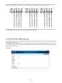
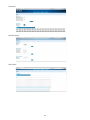
8. Software update
The Ethernet input (RJ45) also serves for software update of the xture by means of the ROBE RDM
Uploader software.
For more details about the ROBE RDM Uploader, please visit https://www.robe.cz/robe-uploader/.

20
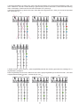
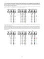
9. Incorporation of new dots (after replacing faulty dots)
In case that some faulty dots have been replaced with the new dots, the following error message will appear
after switching the xture on:
"Ch. 1 Cfg Mismatch" - it means new dots at LED output 1
"Ch. 2 Cfg Mismatch" - it means new dots at LED output 2
"Ch. 3 Cfg Mismatch" - it means new dots at LED output 3
"Ch. 4 Cfg Mismatch" -it means new dots at LED output 4
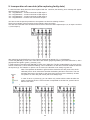
You have to use the special procedure to incorporate new dots into existing dot lines.
There is an example of this procedure for the following dots connection:
The dots are connected to the ArcPixel Power and the 5 dots have been replaced (dot 1,2, at output 1 and dot
1,2,3 at output 2).
After switching the ArcPixelPower on,the following message will appear "Ch. 1 Cfg Mismatch".
1.Press the
[ENTER]
to enter menu "New Dot" and use the
[UP] and [DOWN
] to browse items Sel 1, Sel 2
(appropriate dot lights in green) - pictures (1),(2).
2. Select the dot 2 and press
the
[ENTER] to enter menu "Miss Dot".The Dot 2 starts ashing in green and by
means of items
Sel 1, Sel 2 select the following colour combination of dots when the blue dot will be after the
dot 2-picture (3). The situation on picture 4 is not correct, the blue dot is not closely to green dot.
1 2 3
Note: The replaced dot ashes in green and the dot before this dot (near to the ArcPi-
xelPower) has to be in red and the dot after the ashing dot has to be in blue. The red
and blue dots have to be closely to the green dot (not second or the third.dot). At least
one position of colour dot (red or blue) has to be always kept.
In case of dot 2 on picture (3) you can select only variant with the blue dot after the
green dot becase the dot 1 has not been incorporated to the dot line yet and cannot
shine in red colour.
La page est en cours de chargement...
La page est en cours de chargement...
La page est en cours de chargement...
La page est en cours de chargement...
La page est en cours de chargement...
La page est en cours de chargement...
La page est en cours de chargement...
-
 1
1
-
 2
2
-
 3
3
-
 4
4
-
 5
5
-
 6
6
-
 7
7
-
 8
8
-
 9
9
-
 10
10
-
 11
11
-
 12
12
-
 13
13
-
 14
14
-
 15
15
-
 16
16
-
 17
17
-
 18
18
-
 19
19
-
 20
20
-
 21
21
-
 22
22
-
 23
23
-
 24
24
-
 25
25
-
 26
26
-
 27
27


Anolis ArcPixel™ Power Manuel utilisateur
- Catégorie
- Stroboscopes
- Taper
- Manuel utilisateur
dans d''autres langues
- English: Anolis ArcPixel™ Power User manual
Documents connexes
Autres documents
-
Briteq BT-NODE28 (3pin XLR) Le manuel du propriétaire
-
 Fumagalli Sauro 1100 Manuel utilisateur
-
Elation COLOUR CHORUS Series Manuel utilisateur
-
Vari-Lite VLZ WASH Manuel utilisateur
-
 afx light PARLED-W15BK Le manuel du propriétaire
-
-
-
Martin MAC Allure Profile Mode d'emploi
-
Elation SIXBAR 500 Manuel utilisateur
-
Elation SIXBAR 1000 Manuel utilisateur

