Sony CNU-500 Installation and Maintenance Manual
- Taper
- Installation and Maintenance Manual

CAMERA COMMAND NETWORK UNIT
CNU-500
INSTALLATION AND MAINTENANCE MANUAL
1st Edition
Serial No. 10001 and Higher: CNU-500 (UC)
Serial No. 30001 and Higher: CNU-500 (J)
Serial No. 40001 and Higher: CNU-500 (CE)

CNU-500
! WARNING
This manual is intended for qualified service personnel only.
To reduce the risk of electric shock, fire or injury, do not perform any servicing other than that
contained in the operating instructions unless you are qualified to do so. Refer all servicing to
qualified service personnel.
! WARNUNG
Die Anleitung ist nur für qualifiziertes Fachpersonal bestimmt.
Alle Wartungsarbeiten dürfen nur von qualifiziertem Fachpersonal ausgeführt werden. Um die
Gefahr eines elektrischen Schlages, Feuergefahr und Verletzungen zu vermeiden, sind bei
Wartungsarbeiten strikt die Angaben in der Anleitung zu befolgen. Andere als die angegeben
Wartungsarbeiten dürfen nur von Personen ausgeführt werden, die eine spezielle Befähigung
dazu besitzen.
! AVERTISSEMENT
Ce manual est destiné uniquement aux personnes compétentes en charge de l’entretien. Afin
de réduire les risques de décharge électrique, d’incendie ou de blessure n’effectuer que les
réparations indiquées dans le mode d’emploi à moins d’être qualifié pour en effectuer d’autres.
Pour toute réparation faire appel à une personne compétente uniquement.

1 (E)
CNU-500
Table of Contents
Manual Structure
Purpose of this manual ........................................................................................ 2 (E)
Contents ............................................................................................................... 2 (E)
Related manuals................................................................................................... 2 (E)
1. Installation
1-1. Supplied Accessories ............................................................................1-1 (E)
1-2. Connectors and Cable ...........................................................................1-1 (E)
1-2-1. Connector Input and Output signals.....................................1-1 (E)
1-2-2. Connection Connector..........................................................1-2 (E)
1-2-3. Cable Wiring Diagram .........................................................1-2 (E)
1-3. Functions of Switches on AT Board .....................................................1-3 (E)
1-4. Installation.............................................................................................1-4 (E)
1-4-1. Installation Conditions .........................................................1-4 (E)
1-4-2. Outside Dimensions .............................................................1-4 (E)
1-4-3. Rack Mounting.....................................................................1-5 (E)
1-5. Instance of System Configuration.........................................................1-6 (E)
2. Service Overview
2-1. Removal of Cabinet...............................................................................2-1 (E)
2-2. Disconnecting/ Connecting Flexible Card Wire ...................................2-2 (E)
2-3. Notes on Switching Regulator ..............................................................2-2 (E)
2-4. Fuse Replacement .................................................................................2-2 (E)
2-4-1. Fuse on AT-100 Board.........................................................2-2 (E)
2-4-2. Fuse in Switching Regulator ................................................2-3 (E)
2-5. Notes on Service ...................................................................................2-4 (E)
2-5-1. Note on Replacement of Parts..............................................2-4 (E)
2-5-2. P ROM IC ............................................................................2-4 (E)
2-6. Self-Diagnosis .......................................................................................2-4 (E)
2-6-1. Equipment Required.............................................................2-4 (E)
2-6-2. Connection ...........................................................................2-4 (E)
2-6-3. Initial Setting ........................................................................2-4 (E)
2-6-4. Self-Diagnosis Mode............................................................2-5 (E)
2-6-5. Switch Setting After Completion of Self-Diagnosis ............2-8 (E)

2 (E)
CNU-500
Purpose of this manual
This manual is the installation and maintenance manual for Camera Command
Network Unit CNU-500.This manual describes the information items necessary
when the unit is supplied and installed, items on maintenance, assuming use of
system and service engineers.
Contents
This followings are summaries of the each section for understanding the manual.
Section 1 Installation
Describes information about connector input/output signals, instance of configura-
tion and function of internal switches.
Section 2 Service Overview
Describes information about board locations, circuit description replacement of part
and notes on services.
Related manuals
Besides this installation and maintenance manual the following manuals are avail-
able for this unit.
• Operation Manual (Supplied with this unit)
This manual is necessary for application and operation of this unit.
• System Manual (Available on request)
This manual is necessary for connection and operation of this unit and other periph-
eral equipment.
If this manual is required, please contact your local Sony Sales Office/Service
Center.
• Maintenance Manual (Available on request)
This manual describes the information items that premise the service based on the
component parts such as parts list, semiconductor pin assignments, block diagrams,
schematic diagrams and board layout.
If this manual is required, please contact your local Sony Sales Office/Service
Center.
Manual Structure

1-1 (E)
CNU-500
5
9
6
1
Section1
Installation
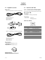
1-1. Supplied Accessories
Power cord: 1
[for UC] (Sony Part No. 1-551-812-11) with 3P-plug
Cable length about 2.4 m
Rated Voltage 125 V
Rated Current 7 A
[for CE] (Sony Part No. 1-782-929-11) without plug
Cable length about 2.5 m
Rated Voltage 250 V
Rated Current 10 A
Plug Holder (B): 1
(Sony Part No. 2-990-242-01:for UC)
Plug Holder (C): 1
(Sony Part No. 3-613-640-01:for CE)
Operation Manual: 1
Installation and Maintenance Manual: 1
1-2. Connectors and Cable
1-2-1. Connector Input and Output signals
Main connector input and output signals are shown below.
BNC connector 75
ZZ
ZZ
Z
[Input Signal]
. REFERENCE 300 mVp-p, loop through
[Output Signal]
. CHARACTER 700 mVp-p,
300 mVp-p (SYNC)
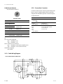
RS232C (9P, FEMALE)
(EXTERNAL VIEW)
No. Signal Specifications
1 DCD IN DATA CARRIER DETECT
2 RXD (+) IN RECEIVED DATA
3 TXD (+) OUT TRANSMITTED DATA
4 DTR OUT DATA TERMINAL READY
5 SIGNAL GND SIGNAL GND
6 DSR IN DATA SET READY
7 RTS OUT REQUEST TO SEND
8 CTS OUT CLEAR TO SEND
9NC _
21
4.75
12.7
1.5
5
13.75
23.0
11.9
6.30

1-2 (E)
CNU-500
Black
White
White
Brown
White
Red
Red
Brown Brown
Orange
1
2
3
4
8
5
6
7
1
2
3
4
8
5
6
7
1
2
3
4
5
6
7
8
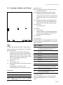
REMOTE (8P, FEMALE)
RCP/CCU/MSU/VCS/AUX
(EXTERNAL VIEW)
No. Signal Specifications
1 TX (+) CNU SERIAL DATA
2 TX (_)
3 RX (+) MSU/RCP/CCU/VCS/AUX
4 RX (_) SERIAL DATA
5 TX GND GND for TX
6 POWER (+) *1
7 POWER (_) *1
8 SPARE
CHASSIS GND CHASSIS GND
*1
CCU1 to CCU6 Connectors
6pin . . POWER (+) IN
7pin . . POWER (_) IN
RCP1 to RCP6, AUX Connectors
6pin . . POWER (+) OUT (RCP POWER +30 V)
7pin . . POWER (_) OUT (GND for Power)
MSU/VCS Connectors
NOT USED
1-2-3. Cable Wiring Diagram
CCA-5 CABLE(REMOTE CONNECTOR)
1-2-2. Connection Connector
Connection made with the connector panels during instal-
lation or service, should be made with the connectors/
complete cable assemblies specified in the following list,
or equivalent parts.
Connector Name Connectoin Connector/Cable
REFERENCE 1-569-370-12 Connector, BNC
CHARACTER
(BNC)
RS232C 1-566-354-11
(9P, FEMALE) D-SUB, 9P MALE
CCU 1-766-848-11 PLUG, 8P MALE
RCP or CCA cable ASSY (option)
MSU CCA-5-10(10 m)
VCS CCA-5-3 (3 m)
AUX
(8P, FEMALE)
1-2. Connectors and Cable

1-3 (E)
CNU-500
AT-100 BOARD(A SIDE)
S1102
23456789101112131415
H
G
F
E
D
C
B
A
S
P
O
N
M
L
K
J
R
F1
D4
S4 S5 S6S3
S2
S1100
RV1
1
1-3. Functions of Switches on AT Board
. S2
n
To activate the switches S2-4 and S2-5, modification for
the RCP is required. For more details, refer to installation
manual of BKP-7933.
1: Selects the mode of the CHARACTER output
signal when no signal is input to the REFERENCE
terminal. When the switch is set to ON, the output
signal becomes 625-line. When this switch is set to
OFF, the output signal becomes 525-line.
Factory-setting : OFF
2, 3: Not Used
Factory-setting : OFF
4, 5: Operation mode of the RCP PREVIEW switch can
be changed.
Factory-setting of S2-4 and S2-5: OFF
Setting and operation of each mode are as follow:
[Mode setting]
SW No. SETTING POSITION
2-4 OFF ON OFF ON
2-5 OFF OFF ON ON
MODE MON ALT1 ALT Reserve
(Factory setting)
[Operation mode]
MON: Preview picture can be seen during pressing the
RCP PREVIEW switch.
ALT1:Preview picture appears by pressing the RCP
PREVIEW switch once, however, it cannot be
turned off. (Preview picture can be changed when
the PREVIEW switch is set to ON from the other
RCP.)
ALT: Preview picture appears when pressing the RCP
PREVIEW switch once, and it disappears when
pressing the RCP PREVIEW switch once again.
6 to 8: Not Used
Factory-setting : OFF
. S3 (MODE)
0: Factory-setting
1: Enable the selection of the page displayed on the
monitor screen connecting to the CHARACTER
terminal using UP/DOWN switch.
2 to F: Not used
. S4 (UP/DOWN)
Enable the selection of the page displayed on the monitor
screen by setting the S3 switch(MODE) to 1.Contents of
pages are as follows.
Page Contents
1 No display(when the power is turned on)
If any fault has been detected during self diagnosis,
the corresponding details are displayed.
2 The connection states of cameras 1 to 6 are
displayed.
3 Not used
4 Not used
5 The results of automatic setup for cameras 1 to 6 are
displayed.
6 Not used
7 DIAGNOSIS OF ALL CAMERAS (The results of self
diagnosis for cameras 1 to 6 are displayed).
8 Not used
9 DIAGNOSIS OF ONE CAMERA (The result of self
diagnosis for the selected camera are displayed).
10 DATA OF ALL CAMERAS (The settings for all
connected cameras are displayed.)
11 DATA OF ONE CAMERA (The setting for the
selected camera is displayed.)
. S5 (SET/CANCEL)
Selects the displayed item(item) or the camera(CAM)
when displaying the page 9, 10 or 11 on the monitor
screen.
1-3. Functions of Switches on AT Board

1-4 (E)
CNU-500
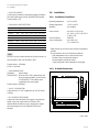
POWER
CAMERA COMMAND NETWORK UNIT
408
65
123.8
212.7
263.5
4–M4
28
44
7
393
424
482
465
. S6 (SYNC ON/OFF)
Used to specify whether a synchronizing signal is added to
the video signal output from the CHARACTER terminal.
Factory-setting : ON
. S1100 (BAUD RATE SETTING)
SW No. Setting Position
S1100-2 ON OFF OFF OFF OFF OFF OFF
S1100-3 OFF ON OFF OFF OFF OFF OFF
S1100-4 OFF OFF ON OFF OFF OFF OFF
S1100-5 OFF OFF OFF ON OFF OFF OFF
S1100-6 OFF OFF OFF OFF ON OFF OFF
S1100-7 OFF OFF OFF OFF OFF ON OFF
S1100-8 OFF OFF OFF OFF OFF OFF ON
BAUD RATE 19,200 9,600 4,800 2,400 1,200 600 300
Unit : bps
n
Be sure to set one of these switches to ON.Never set two or
more switches to ON or all switches to OFF.
Factory-setting : 19,200 bps.
S1100-1 : Not used
. S1102 (OPERATION)
NORMAL: Normal mode
EMERGENCY: When the CNU-500 or master setup unit
does not operate normally, set this switch
to EMERGENCY.The camera can be
controlled by the control panel.
Factory-setting : NORMAL
. D4 (+5 V INDICATOR)
Lights when the +5 Vdc is supplied to the AT-100 board
correctly.
. RV1 (CHARACTER PHASE)
Adjusts the horizontal phase with respect to the reference
signal of the video output from the CHARACTER
terminal.When the monitor is set to external sync signal,
the horizontal position of the CHARACTER can be
adjusted.
1-4. Installation
1-4-1. Installation Conditions
Operating temperature : +5dC to +40dC
Storage temperature : _20dC to +50dC
Humidity : No condense
Power sources : AC 100 V to 120 V(UC)
AC 110 V to 120 V/ AC 220 V
to 240 V(CE)
Power frequency : 50/60 Hz
Power consumption : 4 A (MAX):UC
2.5 A (MAX):CE
. Install the unit in a location as dry and well-ventilated as
possible.
. Do not install the unit in the following conditions.
High temperature room or near the heat source
Excessive dust or mechanical vibration
Intense magnetic and electric fields
A place subjected to direct sunlight or strong light
1-4-2. Outside Dimensions
(Unit : mm)
1-3. Functions of Switches on AT Board
1-4. Installation

1-5 (E)
CNU-500
12.7
31.8
12.7
31.8
12.7
1
2
3
4
5
6
7
8
9
12.7
15.9
15.9
12.7
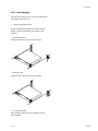
1-4-3. Rack Mounting
The unit can be mounted in a 19-inch EIA standard rack.
(The height of this unit is 1U.)
1. Without using the slide rails
Secure the right and left angles of the unit to the rack
directly. The daily maintenance can perform in this
condition.
. Universal-type Rack
Secure the unit to the rack with the four screws.
. Wide-type Rack
Secure the unit to the rack with the four screws.
2. Using the slide rails
When using the slide rails for rack mounting, refer to
system manual.
1-4. Installation

1-6 (E)
CNU-500
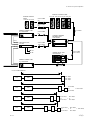
1-5. Instance of System Configuration
1-5. Instance of System Configuration
ENG/EFP LENS
COLOR VIDEO CAMERA
BVP-950 series
ELECTRONIC
VIEWFINDER
BVF-55/55CE
CAMERA ADAPTOR
CA-570/570P
CA-550/550P
STUDIO ZOOM LENS
TRIAX CABLE (*2)
TRIAX CABLE (*2)
COLOR VIDEO CAMERA
BVP-900 series
BVF-7700/7700P
ELECTRONIC VIEWFINDER
BVF-77/77CE
2" VF(BVF-20W/20WCE)
1.35" COLOR VF(BVF-C10W)
1.5" VF(BVF-10/10CE)
ENG/EFP LENS
COLOR VIDEO CAMERA
BVP-E10 series
*2: TRIAX CABLE LENGTH
Diameter
8.5 mm
14.5 mm
Maximun length
1000 mm
2000 mm

1-7 (E)
CNU-500
REMOTE CONTROL
PANEL
RCP-700 RCP-701
CCA-5 CABLE
(*1)
CCA-5 CABLE
(*1)
CCA-5 CABLE
(*1)
CCA-5 CABLE
(max. 200 m)
REMOTE CONTROL PANEL
RCP-720 RCP-721 RCP-740 RCP-741
CCA-5 CABLE
(*1)
CCA-5 CABLE
(max. 200 m)
CCA-5 CABLE
(*1)
CAMERA COMMAND
NETWORK UNIT
CNU-700/500
MASTER SETUP UNIT
MSU-700A/750
CAMERA CONTROL UNIT
CCU-700A/700AP
VIDEO SELECTOR
VCS-700
PIX
WF
PIX 2
PIX 2
WF 2
WF 2
CAMERA CONTROL UNIT
CCU-700A/700AP
*1: CCA-5 CABLE LENGTH
CCU CNU
200m
RCP-740/1
RCP-720/1
RCP-700/1
CCU CNU
160m
RCP-740/1
or
RCP-720/1
+
+
RCP-700/1
CCU CNU
90m
RCP-740/1
or
RCP-720/1
RCP-740/1
or
RCP-720/1
+
RCP-740/1
or
RCP-720/1
+
RCP-700/1
RCP-740/1
or
RCP-700/1
CCU CNU
45m
1-5. Instance of System Configuration


2-1 (E)
CNU-500
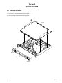
PWH3 x 5
PWH3 x 5
Front panel
M4 x 20
M4 x 20
Top panel
Section 2
Service Overview
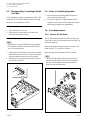
2-1. Removal of Cabinet
1. Loosen the two screws and remove the front panel.
2. Remove the four screws and remove the top panel.

2-2 (E)
CNU-500
2-2. Disconnecting/ Connecting Flexible
Card Wire
The four flexible card wires are used between the AT-100
board and CN-125A/125B boards.Be careful not to bend
these wires. This shortens the wire life.
Disconnecting
1. Turn off the power of the unit.
2. Slide portion A in the direction of the arrow and
disconnect the flexible card wire.
Connecting
n
. Be careful not to insert the flexible card wire obliquely.
. Check that the conductive surface of the flexible card
wire is not soiled with dust.
1. Slide portion A in the direction of the arrow and insert
the flexible card wire as far as it will go into connector
with the conductive surface of the wire put down.
2. Slide portion A in the opposite direction of the arrow
and lock each connector.
2-3. Notes on Switching Regulator
1. Since the unit has a switching regulator, beware of
electric shock the primary side.
2. If the power supply unit is operated under no load
conditions, the power unit will be broken-down.Never
check the power supply unit independently.
2-4. Fuse Replacement
2-4-1. Fuse on AT-100 Board
The AT-100 board has the fuse which shuts off the power.
If any fault occorrs or flows the rush current in the unit, the
fuse will be burnt-out.
Remove the top panel and replace the fuse on the AT-100
board. (Refer to “2-1. Removal of Cabinet”.)
When replacing the fuse, remedy the cause of troulbe.
n
. The fuse should be replaced after the power switch is
turned off and the plug of the power cord is pulled out.
. The fuse should be replaced with specified parts de-
scribed on Section 3 Spare Parts.
2-2. Disconnecting/ Connecting Flexible Card Wire
2-3. Notes on Switching Regulator
2-4. Fuse Replacement
A
Conductive
surface

2-3 (E)
CNU-500
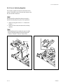
2-4-2. Fuse in Switching Regulator
The switching regulator has the fuse which shuts off the
powers. If any fault occurrs or flows the rush current in the
unit, the fuse will be burnt-out.
n
The fuse should be replaced after the power switch is
turned off and the plug of the power cord is pulled out.
1. Remove the top panel. (Refer to “2-1. Removal of
Cabinet”.)
2. Remove the four screws and remove the switching
regulator.
n
. When replacing the fuse, remedy the cause of trouble.
. The fuse should be replaced with specified parts de-
scribed on “FRAME” of Section 3 Spare Parts.
2-4. Fuse Replacement
Switching
regulator
PSW3 x 6
PSW3 x 6

2-4 (E)
CNU-500
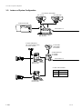
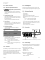
RCP1 RCP2 RCP3 RCP4 RCP5 RCP6 VCS AUX
REFERENCE
CCU1 CCU2 CCU3 CCU4 CCU5 CCU6 MSU
AC IN
RS232C
CCA-5-3 or CCA-5-10
AC
VBS or BB
Monitor
D-SUB 9-pin
short plug
75Z terminator
Signal genertor
Connect between the connectors to be checked using a CCA-5 cable
2-5. Notes on Service
2-5-1. Note on Replacement of Parts
1.
WARNING
Safety Related Components Warning
Components marked ! are critical to safe operation.
Therefore, specified parts should be used in the case of
replacement.
2. Standardization of Parts
Some repair parts supplied by Sony differ from those
used for the unit. These are because of parts common-
ality and improvement.
Parts list has the present standardized repair parts.
3. Stock of Parts
Parts marked with “o” at SP(Supply Code) column of
the spare parts list may be not stocked. Therefore, the
delivery date will be delayed.
4. Units Representation
The following represented units are changed or
omitted in writing.
Units Representation
Capacitance µFuF
Inductance µHuH
Resistance Z Abbreviation
Temperature dC XXX-DEG-C
5. Destination Representation
The part indicated “For J/UC/CE” in the spare parts
list is used in the unit written below.
For J : The part is used in a unit for Japan.
For UC: The part is used in a unit for U.S.A. and
Canada.
For CE : The part is used in a unit for regions except
the above countries.
2-5-2. P ROM IC
Each PROM IC on the PC board has a suffix to its original
designation. This suffix may change according to improve-
ment of IC. Never use and IC having no suffix to its
original designation, because its memory has not been
programmed. Each PROM IC is mounted on the PC board
via socket.
2-6. Self-Diagnosis
CNU-500 has a self-diagnosis program. The state of this
unit can be diagnosed by using this self-diagnosis program.
2-6-1. Equipment Required
. 75Ω terminator
. Coaxial cable x 2
. Monitor (A B/W monitor can be used.)
. Signal generator (A VBS(
*
1) or BB(
*
2) signal can be
output.)
*
1 VBS : Video Burst and Sync Signal
*
2 BB : Black Burst and Sycn Signal
. D-SUB 9-pin connector plug (male) whose pins 2 and 3,
and pins 7 and 8 are shorted. (Referred to as a D-SUB 9-
pin short plug hereafter.)
. CCA-5-3 cable or CCA-5-10 cable x 1
2-6-2. Connection
2-6-3. Initial Setting
Set as described below before performing the self-diagnosis.
. Remove the top panel. (Refer to “2-1, Cabinet Removal”.)
Panel switches of AT-100 board
. S1102(OPERATION) → NORMAL
. S3(MODE) → D
. S6(SYNC) → ON
Inside switches on AT-100 board
. S1100(H7) →S1100-2:ON
Except S1100-2:OFF
. S2(H11) → all OFF
2-5. Notes on Service
2-6. Self-Diagnosis

2-5 (E)
CNU-500
AT-100 Main check mode. (AUTO)
EPROM Check
OPTION FLASH Check
OK
RAM Check
OPTION EEPROM Check
SWITCH Check
OK
WRITE
ERASE
READ
S2
S3
OK
AT-100 Main check mode. (AUTO)
EPROM Check
OPTION FLASH Check
OK
RAM Check
OPTION EEPROM Check
SWITCH Check
OK
WRITE
ERASE
READ
S2
AT-100 Main check mode. (AUTO)
EPROM Check
OPTION FLASH Check
OK
RAM Check
OPTION EEPROM Check
SWITCH Check
OK
WRITE
ERASE
READ
S2
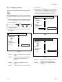
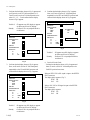
2-6-4. Self-Diagnosis Mode
Activate the self-diagnosis mode following the procedure
below.
n
The self-diagnosis mode of CNU-500 is completed when
the system is terminated normally or when an error occurs.
. Turn on the power switch with the S4 and S5 switches
(on the AT-100 board panel) set to the DOWN and SET
positions, respectively.
a) ROM/RAM Check
. Release the switches when the monitor display shown in
Fig. 1 appears.
Fig. 1
Trouble 1 : Figure 1 is not displayed on the monitor
screen.
Remedy : Confirm if IC45 and its peripheral block
or switches S3, S4, and S5 are not
defective.
Trouble 2 : The RAM check appears as an NG
display.
Remedy : Confirm if IC9 to IC12 are not defective.
b) Switch Check
1. Confirm that Fig. 1 is displayed on the monitor screen,
and set S2-1 to S2-8 sequentially to on (see in Fig. 2).
Next, set S2-8 to S2-1 sequentially to off and confirm
that the monitor display shown in Fig. 3 appears.
Fig. 2
Fig. 3
Trouble 3 : S2 appears as an NG display or appears
as neither an OK nor NG display.
Remedy : Confirm if S2 or its peripheral block is
not defective.
2-6. Self-Diagnosis
S3 S4 S5
UP DOWN SET CANCEL
MODE

2-6 (E)
CNU-500
AT-100 Main check mode. (AUTO)
EPROM Check
OPTION FLASH Check
OK
RAM Check
OPTION EEPROM Check
SWITCH Check
OK
WRITE
ERASE
READ
S2
S3
S4
S5
OK
OK
OK
OK
OK
F
DOWN
CANCEL
N / P CHANGE Check
NTSC
PAL
AT-100 Main check mode. (AUTO)
EPROM Check
OPTION FLASH Check
OK
RAM Check
OPTION EEPROM Check
SWITCH Check
OK
WRITE
ERASE
READ
S2
S3
S4
S5
OK
OK
OK
F
DOWN
OFF
AT-100 Main check mode. (AUTO)
EPROM Check
OPTION FLASH Check
OK
RAM Check
OPTION EEPROM Check
SWITCH Check
OK
WRITE
ERASE
READ
S2
S3
S4
OK
OKF
OFF
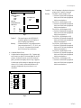
2. Confirm that the display shown in Fig. 3 appears and
set S3 switch (on the AT-100 board panel) to “0”.
Turn S3 switch (on the AT-100 board panel) in the
order of 1, 2, 3, ... F and confirm that the display
shown in Fig. 4 appears.
Trouble 4 : S3 appears as an NG display or appears
as neither an OK nor NG display.
Remedy : Confirm if S3 or its peripheral block is
not defective.
Fig. 4
3. Confirm that the display shown in Fig. 4 appears.
Next, set S4 switch (on the AT-100 board panel)
sequentially to the UP and DOWN positions and
confirm that the display shown in Fig. 5 appears.
Fig. 5
Trouble 5 : S4 appears as an NG display or appears
as neither an OK nor NG display.
Remedy : Confirm if S4 or its peripheral block is
not defective.
4. Confirm that the display shown in Fig. 5 appears.
Next, set S5 switch (on the AT-100 board panel)
sequentially to the SET and CANCEL positions and
confirm that the display shown in Fig. 6 appears.
Fig. 6
Trouble 6 : S5 appears as an NG display or appears
as neither an OK nor NG display.
Remedy : Confirm if S5 or its peripheral block is
not defective.
c) Gen-lock Circuit Check
. Confirm that the display shown in Fig. 6 appears and
throw S5 switch (on the AT-100 board panel) to the
CANCEL position three times.
When an NTSC VBS or BB signal is input to the REFER-
ENCE connector;
The display below appears. (Fig. 7)
NTSC OK
PAL NG
When a PAL VBS or BB signal is input to the REFER-
ENCE connector;
The display below appears.
NTSC NG
PAL OK
2-6. Self-Diagnosis

2-7 (E)
CNU-500
AT-100 Com. check mode. (AUTO)
MSU
CCU1
CCU2
CCU3
CCU4
CCU5
CCU6
RCP1
RCP2
RCP3
RCP4
RCP5
RCP6
VCS
OK
NG
NG
NG
NG
NG
NG
Push [SET] key !!
AT-100 Main check mode. (AUTO)
EPROM Check
OPTION FLASH Check
OK
RAM Check
OPTION EEPROM Check
SWITCH Check
OK
WRITE
ERASE
READ
S2
S3
S4
S5
Check end Push [SET]key
OK
OK
OK
OK
OK
NG
F
DOWN
CANCEL
N / P CHANGE Check
NTSC
PAL
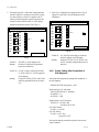
Trouble 8 : An NG message is displayed at the point
where a CCA-5 cable is connected.
Remedy : The MSU ↔ RCP1 display is NG.
→ Confirm if IC902 and its peripheral
block, and IC305 and its peripheral
block are not defective.
The CCU1 ↔ RCP2 display is NG.
→ Confirm if IC304 and its peripheral
block, and IC405 and its peripheral
block are not defective.
The CCU2 ↔ RCP3 display is NG.
→ Confirm if IC404 and its peripheral
block, and IC505 and its peripheral
block are not defective.
The CCU3 ↔ RCP4 display is NG.
→ Confirm if IC504 and its peripheral
block, and IC605 and its peripheral
block are not defective.
The CCU4 ↔ RCP5 display is NG.
→ Confirm if IC604 and its peripheral
block, and IC705 and its peripheral
block are not defective.
The CCU5 ↔ RCP6 display is NG.
→ Confirm if IC704 and its peripheral
block, and IC805 and its peripheral
block are not defective.
The CCU6 ↔ VCS display is NG.
→ Confirm if IC804 and its peripheral
block, and IC903 and its peripheral
block are not defective.
2-6. Self-Diagnosis
Fig. 7
Trouble 7 : The signal input to the REFERENCE
connector appears as an NG display or
the NG display stops halfway.
Remedy : Confirm that IC42 or its peripheral block
(area enclosed with A-13, I-15, G-13, and
G-15 on AT-100 printed circuit board),
and CN1 harness are not defective.
d) Command Block Check
1. Confirm that the display shown in Fig. 7 appears and
set S5 switch (on the AT-100 board panel) to the SET
position. Release S5 switch (on the AT-100 board
panel) just when the display shown in Fig. 8 appears.
Confirm that an OK message is displayed at the point
where a CCA-5 cable is connected and that an NG
message is displayed at the point where it is not
connected.
Fig. 8

2-8 (E)
CNU-500
AT-100 Com. check mode. (AUTO)
MSU
CCU1
CCU2
CCU3
CCU4
CCU5
CCU6
MSU
RCP1
RCP2
RCP3
RCP4
RCP5
RCP6
VCS
AUX
OK
NG
NG
NG
NG
NG
NG
OK
Check end [Please Reset]
OKS10 1
AT-100 Com. check mode. (AUTO)
MSU
CCU1
CCU2
CCU3
CCU4
CCU5
CCU6
MSU
RCP1
RCP2
RCP3
RCP4
RCP5
RCP6
VCS
AUX
OK
NG
NG
NG
NG
NG
NG
OK
S10 1
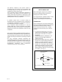
2. Disconnect the CCA-5 cable (that connects between
the MSU and RCP1 connectors) at the RCP1 connec-
tor, then connect it to the AUX connector. Set S5
switch (on the board panel) to the SET position and
release S5 switch when the MSU ↔ AUX display
appears on the monitor screen. (See in Fig. 9.)
Fig. 9
Trouble 9 : The MSU ↔ AUX display is NG.
Remedy : Confirm if IC1003 and its peripheral
block are not defective.
Trouble 10 : A CCA-5 cable is connected, but MSU
↔ RCP1 to MSU ↔ AUX all appear as
an NG display.
Remedy : Confirm if IC1200, IC1201, and IC1203
and their peripheral block are not defec-
tive.
3. After Fig. 9 is displayed, the display shown in Fig. 10
appears in a short time. (The self-diagnosis is then
terminated.)
Fig. 10
Trouble 11 : A D-SUB 9-pin short plug is connected,
but S101 appears as an NG display.
Remedy : Confirm if IC1105, IC1112, IC1101, and
IC1102, and their peripheral block are not
defective.
2-6-5. Switch Setting After Completion of
Self-Diagnosis
Perform the following switch settings after completion of
the self-diagnosis.
. POWER SWITCH (front panel) → OFF
Panel switches of AT-100 board
. S1102 (OPERATION) → NORMAL
. S3 (MODE) → 0
. S6 (SYNC) → ON
Inside switches on AT-100 board
. S1100 (H7) → S1100-2: ON
Except S1100-2: OFF
(For NTSC Model)
. S2 (H11) → All OFF
(For PAL Model)
. S2 (H11) →S2-1: ON
Except S2-1: OFF
After switch resetting, attach the top panel in the reverse
order of removal.
2-6. Self-Diagnosis
La page est en cours de chargement...
La page est en cours de chargement...
-
 1
1
-
 2
2
-
 3
3
-
 4
4
-
 5
5
-
 6
6
-
 7
7
-
 8
8
-
 9
9
-
 10
10
-
 11
11
-
 12
12
-
 13
13
-
 14
14
-
 15
15
-
 16
16
-
 17
17
-
 18
18
-
 19
19
-
 20
20
-
 21
21
-
 22
22


Sony CNU-500 Installation and Maintenance Manual
- Taper
- Installation and Maintenance Manual
dans d''autres langues
- English: Sony CNU-500
Documents connexes
Autres documents
-
Extron RCP 101 Series Manuel utilisateur
-
 Kromschroder VAS, VCS Fiche technique
-
Technicolor - Thomson Camcorder CAMERA TTV 1707 Manuel utilisateur
-
LG PQNFG14B0.ENCXLEU Le manuel du propriétaire
-
Rubbermaid DVPN4400 Le manuel du propriétaire
-
-
