
1
Product Category
IMPORTANT:
Go to for the
complete user guide and installation
instructions before connecting the
product to the power source.
www.extron.com
RCP 101 EU and RCP 101 MK • Setup Guide
Overview
The RCP 101 EU and RCP 101 MK are remote control panels with backlit transport controls for SMP series products. They carry
out the same functions as the SMP front panel transport controls and the USB type A port supports USB ash drives and external
USB portable drives.
The RCP 101 EU ts the opening in a 1-gang EU, Jung AS 500 wallplate, Extron Flex55 mounting system, or other European
frame that accepts 55 mm x 55 mm modules. The RCP 101 MK ts in a standard MK Wall Frame for United Kingdom junction
boxes. The units ship with a metal bracket that enable them to be mounted in the appropriate junction box. The RCP 101 EU also
ships with a metal spacer that can be used for Mounting the RCP 101 EU in a cable raceway (see page 5).
This guide provides basic instructions for an experienced installer to install either of these remote control panels and contains the
following sections:
• RCP 101 Front Panel Features
• RCP 101 Rear Panel Features
• Installation
• Configuration
• Making a Recording
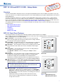
RCP 101 Front Panel Features
The front panel features of the RCP 101 EU and RCP 101 MK are identical apart from the wallplate.
The recording controls have backlit buttons that indicate the current state of the recording operation. Inactive buttons are backlit
dimly to help identify them in low ambient lighting.
A
Record button — Press this button to record one or more of the selected
inputs. The button lights red and remains lit during active recording. The button
has a nub that can be felt with the ngertips.
B
Activity LED — This LED blinks green once when a button press is detected. It
blinks red when a display or notify alarm on the attached SMP is triggered.
C
Stop button — Press this button to stop the active recording. As the recorded
le is nalized, the button blinks. Once the le is nalized, the button lights
solidly.
D
Pause button — Press this button to pause the active recording. While the
recording is paused, this button blinks.
Press Record or Pause to resume recording. Press Stop to end the
recording.
E
Mark button — Press this button to place a chapter marking in the recorded
le. When pressed during active recording, the button momentarily blinks.
The button also lights when JPG thumbnails are created. By default,
thumbnails are created automatically and the interval between the creation of
each thumbnail can be changed by the user on the SMP embedded webpage.
F
USB storage port — Connect a USB compatible media storage device to this
port. This storage device can be any standard external hard drive or USB ash
drive formatted with a compatible le system.
NOTE: SMP models can detect and record to USB storage devices that
use FAT32, VFAT long le name extensions, EXT2, EXT3, EXT4 le
system, or NTFS-formatted storage volumes.
G
USB Storage LED — This LED indicates the status of the storage port:
• It lights green solidly when the recording destination is set to RCP USB or
Auto and the attached storage device is ready for the next recording. The
LED does not turn on if less than 10 minutes of recording space remain on
the storage device.
• It blinks green during a recording to indicate data transfer activity.
• It turns off when no USB storage device is detected or the attached
storage is disconnected.
MARK
RECORD
USB STORAGE
Extron
RCP 101 EU
AA
B
B
C
C
D
D
E
E
F
F
G
G
R
C
P 101 E
U
MARK
RECORD
USB STORAGE
Extron
RCP 101 MK
AA
BB
C
C
DD
E
E
F
F
G
G
Figure 1. RCP 101 EU (top) and
MK (bottom) Front Panels

2
RCP 101 EU and RCP 101 MK • Setup Guide (Continued)
Front Panel Lockout (Executive Mode)
When front panel lockout is on, all the buttons on the RCP 101 are disabled. To toggle between enabling or disabling front panel
lockout, press and hold the Pause and Mark buttons simultaneously for three seconds.
As front panel lockout is enabled, all buttons and the red activity LED (
B
) blink three times. As front panel lockout is disabled,
all the buttons and the green activity LED (
B
) blink three times. If a button is pressed while front panel lockout is enabled, all
buttons blink three times.
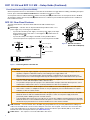
AA
B
B
CC
POWER
12V
1.0A MAX
Figure 2. RCP 101 Rear Panel
(Shown without Wallplate)
Power Receptacle
DC Po
wer Cord
SECTION A–A
Ridges
Smooth
Power Supply
Output Cord
AA
3/16"
(5 mm) Max.
11
2
2
POWER
1.0A MAX
12V
Ground
all Devices
RidgedSmooth
– Return
+12 VDC input
Figure 3. Connecting Power to the RCP 101
RCP 101 Rear Panel Features
The back panel features of the RCP 101 EU and RCP 101 MK are identical (see
gure 2).
A
Power input — The RCP 101 can be powered with the provided 12 VDC, 1.5 A
power supply or by connecting it to the SMP unit.
• To power the unit with a power supply, connect the power supply to this input.
Ensure that the polarity of the wires is correct (gure 3,
1
) and the wires are
stripped correctly (
2
).
• To power the unit by connecting it to the SMP, use the provided cable to
connect this input to the 2-pin power connector on the rear panel of the SMP.
ATTENTION:
• Always use a power supply supplied or specied by Extron. Use of an unauthorized power supply voids all
regulatory compliance certication and may cause damage to the supply and the unit.
• Utilisez toujours une source d’alimentation fournie par Extron. L’utilisation d’une source d’alimentation non
autorisée annule toute conformité réglementaire et peut endommager la source d’alimentation ainsi que l’unité.
• If not provided with a power supply, this product is intended to be supplied by a UL Listed power source marked
“Class2” or “LPS” and rated output 12VDC, minimum 1.0A.
• Si ce produit ne dispose pas de sa propre source d’alimentation électrique, il doit être alimenté par une source
d’alimentation certiée UL de classe 2 ou LPS et paramétré à 12VDC et 1,0A minimum.
• Unless otherwise stated, the AC/DC adapters are not suitable for use in air handling spaces or in wall cavities.
• Sauf mention contraire, les adaptateurs AC/DC ne sont pas appropriés pour une utilisation dans les espaces
d’aération ou dans les cavités murales.
• The installation must always be in accordance with the applicable provisions of National Electrical Code ANSI/
NFPA70, article725 and the Canadian Electrical Code part1, section16. The power supply shall not be
permanently xed to building structure or similar structure.
• Cette installation doit toujours être en accord avec les mesures qui s’applique au National Electrical Code ANSI/
NFPA70, article725, et au Canadian Electrical Code, partie1, section16. La source d’alimentation ne devra pas
être xée de façon permanente à une structure de bâtiment ou à une structure similaire.
B
USB connector — Connect the RCP 101 to the SMP using the provided 15 foot (4.5 meter) USB mini B to USB type A
cable. Insert the USB mini B connector into the USB port on the RCP 101 rear panel. Connect the other end of the cable
to the control USB A port on the rear panel of the SMP. To increase the distance up to 300 feet (100 m), use an Extron
Extender Plus Series twisted pair extender (see www.extron.com).
C
Cable anchor — Use a zip tie to secure the USB cable to this anchor.

3
Product Category
Installation
ATTENTION:
• Installation and service must be performed by authorized personnel only.
• L’installation et l’entretien doivent être effectués par le personnel autorisé uniquement.
• If the RCP 101 will be installed into ne furniture, it is best to hire a licenced, bonded craftsperson to cut the access
hole and perform the physical installation so the surface will not be damaged.
• S’il est prévu d’installer le RCP 101 dans du beau mobilier, il est préférable de faire appel à un artisan autorisé et
qualié pour couper le trou d’accès et réaliser l’installation de telle façon que la surface ne soit pas endommagée.
• Follow all national and local building and electrical codes that apply to the installation site.
• Respectez tous les codes électriques et du bâtiment, nationaux et locaux, qui s’appliquent au site de l’installation.
• All electrical installation should be performed by qualied personnel in accordance with local and national building
codes, re and safety codes, and local and national electrical codes.
• Toute installation électrique devrait être effectuée par un personnel qualié, conformément aux codes du bâtiment,
aux codes incendie et sécurité, et aux codes électriques locaux et nationaux.
Step 1: Prepare the Installation Site
Americans with Disabilities Act (ADA) compliance
When planning where to install these devices, you may need to consider factors affecting accessibility of the button panel such
as height from the oor, distance from obstructions, and how far a user must reach to press the buttons. For guidelines, see
sections 307 (“Protruding Objects”) and 308 (“Reach Ranges”) of the 2010 ADA Standards for Accessible Design available at
http://www.ada.gov/regs2010/2010ADAStandards/2010ADAStandards.pdf.
Site preparation
The RCP 101 EU fits the opening in a 1-gang EU, Jung AS 500 wallplate, Extron Flex55 mounting system, or other European frame
that accepts 55 mm x 55 mm modules. The RCP 101 MK ts in a standard MK wall frame for United Kingdom junction boxes.
The units are shipped with a metal bracket and metal spacer that enable them to be mounted in the appropriate junction box.
Extron offers optional ULListed in-wall junction boxes, external wall boxes (EWBs), and surface or tabletop mounting boxes (see
www.extron.com). To use these optional mounting accessories, follow the instructions provided with the mounting kit.
Step 2: Cable All Devices
Run the power and USB cables to the required destination but do not connect them until you have mounted the unit.
ATTENTION:
• Do not connect a power supply before reading the Attention notications in the “Power connector” section on page 2.
• Ne branchez pas une source d’alimentation externe avant d’avoir lu les mises en garde dans la section
«Powerconnector» sur page 2.

4
RCP 101 EU and RCP 101 MK • Setup Guide (Continued)
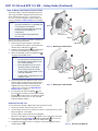
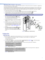
Step 3: Mount the Remote Control Plate
These button plates can be installed directly into the
wall using a standard 1-gang European junction box
(RCP 101 EU) or MK wall frame for United Kingdom
junction boxes (RCP 101 MK). The RCP 101 EU can
also be mounted in a cable raceway (see next page).
NOTES:
• The electrical wall box is not provided and
must be purchased separately.
• Install the electrical wall box by following
the instructions provided by the
manufacturer.
• Use the metal bracket provided with
RCP 101 unit.
The RCP 101 EU (see gure 4) and RCP 101 MK (see
gure 5) are mounted as follows:
1. Decide where the panel will be located. Take
into consideration the position of wall studs and
windows that could obstruct cable runs.
2. Install the electrical wall box (
1
) by following the
instructions provided by the manufacturer.
3. Attach the provided metal mounting bracket (
2
)
using the two provided screws.
NOTES:
• The metal brackets provided with the
EU and MK models are different and
are not interchangeable.
• Ensure the bracket is in the correct
orientation (with the side marked
“Front” facing away from the wall).
• The EU model is attached with screws
at the top and bottom.
• The MK model is attached with screws
on both the sides.
4. Disconnect power from all devices at the source
and run cables through the hole in the wall. Pass
them through the metal mounting bracket and
wallplate and connect them to the rear panel
captive screw connectors (see RCP 101 Rear
Panel Features on page 2).
5. Insert the RCP 101 into the wallplate (
3
) and
press the entire assembly into the metal mounting
bracket (
2
). The RCP 101 is secured to the metal
bracket by two catches (one on each side) and
holds the wallplate in place.
Wa
ll Box
Wallplate
RCP 101 EU
Metal
Mounting Bracket
USB STORAGE
MARK
Extron
Extron
RECORD
11
2
2
3
3
Figure 4. Mounting the RCP 101 EU
RCP 101 MK
Wall Box
Metal
Mounting Bracket
Wallplate
USB STORAGE
MARK
Extron
Extron
RECORD
11
2
2
3
3
Figure 5. Mounting the RCP 101 MK
Removing the RCP 101
To remove the RCP 101 EU or MK from the wall, follow these steps:
1. Disconnect the RCP 101 from the power source.
2. Use the Extron removal tool to release the catches on either side of the control
plate (see gure 6, on the right).
You may need to release both catches individually.
When the control plate is released, the wallplate comes away at the same time.
3. Remove the power cable (figure 2,
A
) and the USB cable (
B
). If necessary,
cut the zip tie securing the USB cable to the cable anchor (
C
).
4. If required, undo the two screws securing the metal mounting bracket to the
wall box (gure 4,
2
).
USB STORAGE
MARK
Extron
Extron
RECORD
Extron
Extron
Insert
to line.
Figure 6. Removing the RCP 101

5
Product Category
Mounting the RCP 101 EU in a cable raceway
The RCP 101 EU can be mounted in a cable raceway. Extron provides a metal spacer that can be used if there is a gap between
the metal mounting bracket and the wallplate.
The spacer looks very similar to the metal mounting bracket, but has a slightly larger center opening, has holes instead of slots
for the mounting screws, and is engraved with the words “Optional Spacer” and “Place behind bracket.” Do not use the spacer
instead of the metal mounting bracket. The spacer has a larger opening and does not hold the RCP securely in the wallplate.
To mount the RCP 101 EU to a raceway using the spacer:
1. Mount an electrical box in the raceway (gure 7,
1
). Follow the instructions provided by the manufacturer.
2. If required, align the screw holes of the provided spacer with the holes in the electrical box (
2
).
3. Align the screw holes in the metal bracket with the holes in the spacer and electrical box (
3
).
NOTE: Ensure that the front surface of the mounting bracket is facing out (away from the wall).
4. Secure the metal bracket and spacer to the junction
box, using the two provided screws (
4
). Leave
the screw heads protruding approximately 1/8 inch
(3.18 mm) from the surface of the spacer.
5. Rotate the metal bracket as necessary to ensure that
the RCP 101 EU is aligned correctly on the mounting
surface.
6. Tighten the screws to secure the bracket to the spacer.
7. Disconnect power from all devices at the source and
run cables through the raceway, junction box, spacer,
metal mounting bracket and wallplate. Connect them
to the rear panel (see Step 2: Cable All Devices on
page 3).
8. Insert the RCP 101 into the wallplate (
5
) and press
the entire assembly into the metal bracket (
6
). The
RCP 101 is secured to the metal bracket by two
catches (one on each side) and holds the wallplate in
place.
Cable Raceway
J
unction Box
Wallplate
Metal Mounting Bracket
Spacer
11
2
2
3
3
4
4
55
6
6
RCP 101 EU
USB STORAGE
MARK
Extron
Extron
RECORD
Figure 7. Mounting in a Cable Raceway
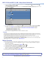
Configuration
SMP Web Page
The RCP 101 can be congured from the SMP web page. Use a PC connected to the same subnet as the SMP.
1. Open a Web browser and enter the IP address of the SMP (see the User Guide for your SMP model).
You may need to log on as admin.
The SMP web page opens.
2. To conrm that the RCP 101 is connected to the SMP, click Configuration (figure 10,
1
, on the following page),
System Settings (
2
), and Unit Identification (
3
).
When the RCP 101 is not connected, or not detected by the SMP, the following information is displayed:
Figure 8. RCP 101 Not Detected
When the neither the RCP 101 EU nor RCP 101 MK is detected by the SMP, the following information is displayed:
Figure 9. RCP 101 Detected

6
For information on safety guidelines, regulatory compliances, EMI/EMF compatibility, accessibility, and related topics,
see the Extron Safety and Regulatory Compliance Guide on the Extron website.
© 2016 - 2018 Extron Electronics — All rights reserved. www.extron.com
All trademarks mentioned are the property of their respective owners.
68-3000-51 Rev. B
10 18
RCP 101 EU and RCP 101 MK • Setup Guide (Continued)
3. To save a recording to the USB device inserted into the RCP 101, click Configuration (
1
), System Settings (
2
),
and Recording Media Selection (
4
).
From the Recording Destination drop-down menu, or the Secondary Recording Destination drop-down menu, as
appropriate, select RCP USB.
11
2
2
3
3
4
4
5
5
Figure 10. SMP Web Page
4. To congure Front Panel Lockout, click Configuration (
1
), System Settings (
2
), and Executive Mode (
5
).
The options shown in figure 9 (see previous page) are available only when the RCP 101 is detected. By default:
• Front Panel Lockout (Executive Mode) is disabled (see Front Panel Lockout (Executive Mode) on page 2).
• Beep when button is pressed is enabled.
• Beep when alarm is triggered is disabled.
Select or deselect the appropriate checkbox to enable or disable those options.
Firmware
The rmware version installed on the RCP 101 must be compatible with the rmware installed on the SMP. To ensure this, the
RCP 101 rmware is managed automatically by the SMP series products. The rmware version of the RCP 101 can be found on
the SMP embedded web page under Configuration > System Settings > Unit Identification.
When the remote control panel is rst connected to the SMP, the SMP checks the rmware version on the RCP 101 and, if
necessary, automatically updates the panel rmware to a compatible version.
If you update the SMP rmware, the RCP 101 rmware is automatically updated at the same time. For more information about
updating SMP rmware, see the SMP User Guide at www.extron.com.
Making a Recording
Once the SMP and RCP 101 are installed, and congured, follow these instructions to make a recording using the RCP 101:
1. Open the SMP web page to ensure the recording will be saved to the correct drive and that the USB drive, if required, is
attached to the correct drive.
2. Start the recording by pressing the Record button (figure 1,
A
, on page 1).
3. If required, add a chapter marking by pressing the Mark button (gure 1,
E
).
4. If required, pause the recording by pressing the Pause button (gure 1,
D
).
Restart the recording by pressing the Pause button a second time or by pressing the Record button.
5. End the recording by pressing the End button (gure 1,
C
).
For more information, see the SMP User Guide at www.extron.com.
-
 1
1
-
 2
2
-
 3
3
-
 4
4
-
 5
5
-
 6
6


Extron RCP 101 Series Manuel utilisateur
- Taper
- Manuel utilisateur
- Ce manuel convient également à
dans d''autres langues
- English: Extron RCP 101 Series User manual
Documents connexes
Autres documents
-
 ALCATECH BMP STUDIO 4 Le manuel du propriétaire
-
Sony VPL-V W100 Manuel utilisateur
-
Renishaw SFP1 Installation & User's Guide
-
Sony VPL-HS60 Le manuel du propriétaire
-
Sony Série PXW-X320 Manuel utilisateur
-
Wacker Neuson RCP-25/120 Manuel utilisateur
-
Wacker Neuson RCP-16/120 60 Hz Manuel utilisateur
-
Sony CNU-500 Installation and Maintenance Manual
