Cameo CLMP10WRGB Manuel utilisateur
- Catégorie
- Projecteurs
- Taper
- Manuel utilisateur
Ce manuel convient également à

MATRIX 300 RGB
LED MATRIX PANEL 5X5 10W RGB
CLMP10WRGB
USER´S MANUAL
BEDIENUNGSANLEITUNG
MANUEL D`UTILISATION
MANUAL DE USUARIO
INSTRUKCJA OBSŁUGI
MANUALE D‘ USO

CONTENTS / INHALTSVERZEICHNIS / CONTENU / CONTENIDO / TREŚĆ / CONTENUTO
ENGLISH
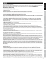
PREVENTIVE MEASURES 3-4
INTRODUCTION 4
CONNECTIONS, OPERATING AND DISPLAY ELEMENTS 5-6
OPERATION 6-8
MOUNTING 9
DMX TECHNOLOGY 10
TECHNICAL DATA 11
MANUFACTURER’S DECLARATIONS 11-12
DMX CONTROL 63-75
DEUTSCH
SICHERHEITSHINWEISE 13-14
EINFÜHRUNG 14
ANSCHLÜSSE, BEDIEN- UND ANZEIGEELEMENTE 15-16
BEDIENUNG 16-18
MONTAGE 19
DMX TECHNIK 20
TECHNISCHE DATEN 21
HERSTELLERERKLÄRUNGEN 21-22
DMX STEUERUNG 63-75
FRANCAIS
MESURES PRÉVENTIVES 23-24
INTRODUCTION 24
RACCORDEMENTS, ÉLÉMENTS DE COMMANDE ET
D’AFFICHAGE 25-26
MODE D’UTILISATION 26-28
MONTAGE 29
TECHNOLOGIE DMX 30
CARACTÉRISTIQUES TECHNIQUES 31
DÉCLARATIONS DU FABRICANT 31-32
PILOTAGE EN MODE DMX 63-75
ESPAÑOL
MEDIDAS DE SEGURIDAD 33-34
INTRODUCCIÓN 34
CONEXIONES, ELEMENTOS DE MANEJO Y ELEMENTOS DE
VISUALIZACIÓN 35-36
FUNCIONAMIENTO 36-38
MONTAJE 39
TECNOLOGÍA DMX 40
DATOS TÉCNICOS 41
DECLARACIONES DEL FABRICANTE 41-42
CONTROL DMX 63-75
POLSKI
ŚRODKI OSTROŻNOŚCI 43-44
WPROWADZENIE 44
GNIAZDA, PANEL OBSŁUGI I WSKAŹNIKI 45-46
OBSŁUGA 46-48
MONTAŻ 49
TECHNIKA DMX 50
DANE TECHNICZNE 51
OŚWIADCZENIA PRODUCENTA 51-52
STEROWANIE DMX 63-75
ITALIANO
MISURE PRECAUZIONALI 53-54
INTRODUZIONE 54
CONNESSIONI, ELEMENTI DI COMANDO E VISUALIZZAZIONE 55-56
UTILIZZO 56-58
MONTAGGIO 59
TECNOLOGIA DMX 60
DATI TECNICI 61
DICHIARAZIONI DEL PRODUTTORE 61-62
CONTROLLO DMX 63-75

3
DMX
DEUTSCHFRANCAIS
ESPAÑOL
ENGLISH
ITALIANO POLSKI
ENGLISH
YOU‘VE MADE THE RIGHT CHOICE!
We have designed this product to operate reliably over many years. Please read this User‘s Manual carefully, so that you can begin making
optimum use of your Cameo Light product quickly. Learn more about Cameo Light on our website WWW.CAMEOLIGHT.COM.
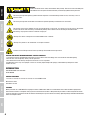
PREVENTIVE MEASURES
1. Please read these instructions carefully.
2. Keep all information and instructions in a safe place.
3. Follow the instructions.
4. Observe all safety warnings. Never remove safety warnings or other information from the equipment.
5. Use the equipment only in the intended manner and for the intended purpose.
6. Use only sufficiently stable and compatible stands and/or mounts (for fixed installations). Make certain that wall mounts are properly installed and
secured. Make certain that the equipment is installed securely and cannot fall down.
7. During installation, observ e the applicable safety regulations for your country.
8. Never install and operate the equipment near radiators, heat registers, ovens or other sources of heat. Make certain that the equipment is
always installed so that is cooled sufficiently and cannot overheat.
9. Never place sources of ignition, e.g., burning candles, on the equipment.
10. Ventilation slits must not be blocked.
11. This appliance is designed exclusively for indoor use, do not use this equipment in the immediate vicinity of water (does not apply
to special outdoor equipment - in this case, observe the special instructions noted below). Do not expose this equipment to flammable
materials, fluids or gases.
12. Make certain that dripping or splashed water cannot enter the equipment. Do not place containers filled with liquids, such as vases or
drinking vessels, on the equipment.
13. Make certain that objects cannot fall into the device.
14. Use this equipment only with the accessories recommended and intended by the manufacturer.
15. Do not open or modify this equipment.
16. After connecting the equipment, check all cables in order to prevent damage or accidents, e.g., due to tripping hazards.
17. During transport, make certain that the equipment cannot fall down and possibly cause property damage and personal injuries.
18. If your equipment is no longer functioning properly, if fluids or objects have gotten inside the equipment or if it has been damaged in
anot her way, switch it off immediately and unplug it from the mains outlet (if it is a powered device). This equipment may only be repaired
by authorized, qualified personnel.
19. Clean the equipment using a dry cloth.
20. Comply with all applicable disposal laws in your country. During disposal of packaging, please separate plastic and paper/cardboard.
21. Plastic bags must be kept out of reach of children.
FOR EQUIPMENT THAT CONNECTS TO THE POWER MAINS:
22. CAUTION: If the power cord of the device is equipped with an earthing contact, then it must be connected to an outlet with a protective
ground. Never deactivate the protective ground of a power cord.
23. If the equipment has been exposed to strong fluctuations in temperature (for example, after transport), do not switch it on immediately.
Moisture and condensation could damage the equipment. Do not switch on the equipment until it has reached room temperature.
24. Before connecting the equipment to the power outlet, first verify that the mains voltage and frequency match the values specified on the
equipment. If the equipment has a voltage selection switch, connect the equipment to the power outlet only if the equipment values and the
mains power values match. If the included power cord or power adapter does not fit in your wall outlet, contact your electrician.
25. Do not step on the power cord. Make certain that the power cable does not become kinked, especially at the mains outlet and/or power
adapter and the equipment connector.
26. When connecting the equipment, make certain that the power cord or power adapter is always freely accessible. Always disconnect the
equipment from the power supply if the equipment is not in use or if you want to clean the equipment. Always unplug the power cord and
power adapter from the power outlet at the plug or adapter and not by pulling on the cord. Never touch the power cord and power adapter
with wet hands.
27. Whenever possible, avoid switching the equipment on and off in quick succession because otherwise this can shorten the useful life of
the equipment.
28. IMPORTANT INFORMATION: Replace fuses only with fuses of the same type and rating. If a fuse blows repeatedly, please contact an
authorised service centre.
29. To disconnect the equipment from the power mains completely, unplug the power cord or power adapter from the power outlet.
30. If your device is equipped with a Volex power connector, the mating Volex equipment connector must be unlocked before it can be re-
moved. However, this also means that the equipment can slide and fall down if the power cable is pulled, which can lead to personal injuries
and/or other damage. For this reason, always be careful when laying cables.
31. Unplug the power cord and power adapter from the power outlet if there is a risk of a lightning strike or before extended periods of disuse.
32. The device must only be installed in a voltage-free condition (disconnect the mains plug from the mains).
33. Dust and other debris inside the unit may cause damage. The unit should be regularly serviced or cleaned (no guarantee) depending on
ambient conditions (dust etc., nicotine, fog) by qualified personnel to prevent overheating and malfunction.
34. Please keep a distance of at least 0.5 m to any combustible materials.
35. Power cables to power multiple devices must have a cross-section of at least 1.5 mm². Within the EU, the cables must correspond to
H05VV-F, or similar. Suitable cables are offered by Adam Hall. With these cables, you can connect multiple devices via the power OUT con-
nection to the power IN connection of an additional device. Make sure that the total current consumption of all connected devices does not
exceed the specified value on all connected devices (label on the device). Make sure to keep power cable connections as short as possible.

4
DMX
ITALIANO
POLSKI
ESPAÑOL
FRANCAIS
DEUTSCHENGLISH
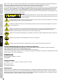
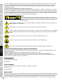
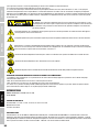
CAUTION:
To reduce the risk of electric shock, do not remove cover (or back). There are no user serviceable parts
inside. Maintenance and repairs should be exclusively carried out by qualified service personnel.
The warning triangle with lightning symbol indicates dangerous uninsulated voltage inside the unit, which may cause an
electrical shock.
The warning triangle with exclamation mark indicates important operating and maintenance instructions.
The housing surface of the spotlight can heat up to temperatures as high as 70 °C in regular use. Ensure that it is not possible
to come into contact with the housing unintentionally. Always allow sufficient time for the lamp to cool down before
dismantling, carrying out maintenance work or charging etc.
Warning! This device is designed for use below 2000 metres in altitude.
Warning! This product is not intended for use in tropical climates.
Caution! Intense LED light source! Risk of eye damage. Do not look into the light source.
CAUTION! IMPORTANT INFORMATION ABOUT LIGHTING PRODUCTS!
1. The product has been developed for professional use in the field of event technology and is not suitable as household lighting.
2. Do not stare, even temporarily, directly into the light beam.
3. Do not look at the beam directly with optical instruments such as magnifiers.
4. Stroboscope effects may cause epileptic seizures in sensitive people! People with epilepsy should definitely avoid places where
strobes are used.
INTRODUCTION
LED MATRIX PANEL 5X5 10 W RGB
CLMP10WRGB
CONTROL FUNCTIONS
3-channel, 5-channel, 19-channel, 28-channel, 78-channel DMX control
Master/slave mode
Standalone function
FEATURES
Matrix panel with 25 x 10 W RGB LEDs. Single pixel control. 5 DMX modes. DMX-512 control. Master/slave mode. Standalone programmes.
Sound control via built-in microphone. Safety eyelet and swivel bracket included. 2 Omega mounting brackets included. Integrated connection
system for mounting an unlimited number of elements horizontally and up to five elements vertically. Operating voltage 100-240 V AC/50-60 Hz.
Power consumption 180 W.

5
DMX
DEUTSCHFRANCAIS
ESPAÑOL
ENGLISH
ITALIANO POLSKI
2 1
3
4
7
9 8
11 10
5
6
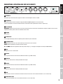
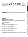
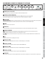
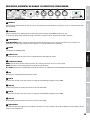
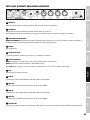
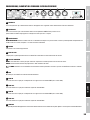
CONNECTIONS, OPERATING AND DISPLAY ELEMENTS
1
POWER IN
Blue power input socket for power supply to the device. A suitable power cable is included.
2
POWER OUT
White power output socket for the power supply of additional CAMEO spotlights. Ensure that the total
current consumption of all connected devices does not exceed the value specified on the device in amperes (A).
3
FUSE HOLDER
IMPORTANT: Replace the fuse only with a fuse of the same type and of the same value according to the stamp on the device! In the event of
repeated fuse failure, please contact an authorised service centre.
4
POWER
On/off switch.
5
LED DISPLAY
The four-digit LED display shows the operating mode and other system information.
6
OPERATING KEYS
MODE: Selection of the main menu items. Move up one level in the menu structure.
ENTER: Confirms programme selection and value changes.
UP and DOWN: Selection of operation mode and system settings, e.g. changing of microphone sensitivity and DMX address.
7
MIC
Microphone for music control mode
8
DMX IN
Male 3-pin XLR socket for connection to a DMX control device (e.g. DMX console).
9
DMX OUT
Female 3-pin XLR socket for sending the DMX control signal.
10
DMX IN
Male 5-pin XLR socket for connection to a DMX control device (e.g. DMX console).
11
DMX OUT
Female 5-pin XLR socket for sending the DMX control signal.
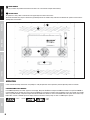
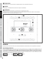
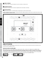
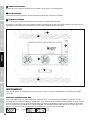
12
FAN
There are three case fans on the back of the device. Ensure that the fans are not covered and that air can circulate freely.
13
VENTILATION SLITS
Ensure that the ventilation slits are not covered and that air can circulate freely.

6
DMX
ITALIANO
POLSKI
ESPAÑOL
FRANCAIS
DEUTSCHENGLISH
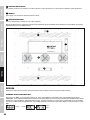
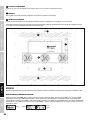
14
CARRY HANDLE
Two carry handles are provided at the back of the device so as to facilitate transport and mounting.
15
SAFETY EYELET
An eyelet for a safety cable is to be found at the upper edge of the device at the back.
Overhead installation may only be carried out by qualified personnel. A suitable safety cable must be fitted to the eyelet to ensure that the
spotlight does not fall down.
15
13
14
12
14
13
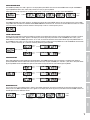
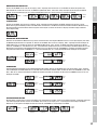
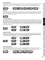
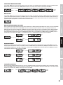
A few seconds after being switched on, the spotlight is ready for operation and the previously selected operating mode is activated.
CONFIGURE DMX START ADDRESS
Press MODE repeatedly until “Addr” appears in the display. Now press ENTER and configure the DMX start address using UP and DOWN as
required (A001–A512). Confirm your entry by pressing ENTER. For synchronous control of several spotlights of the same model using a DMX
device (e.g. DMX console), configure the lights with identical DMX start addresses and the same DMX mode setting and connect them using
DMX cables. If there is no DMX signal, the display characters will flash. Flashing stops as soon as a DMX signal is present.
UP/DOWN
-> ENTER
<- MODE
-> ENTER->
OPERATION

7
DMX
DEUTSCHFRANCAIS
ESPAÑOL
ENGLISH
ITALIANO POLSKI
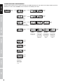
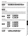
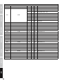
CONFIGURE DMX MODE
Press MODE repeatedly until “ChAn” appears in the display. Now press ENTER and select the desired DMX mode using UP and DOWN as
required (DMX 03Ch, 05Ch, 19Ch, 28Ch, 78Ch). Confirm your entry by pressing ENTER.
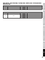
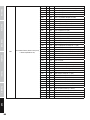
Tables with the channel assignment of the different DMX modes can be found in these instructions under DMX CONTROL.
UP/DOWN-> ENTER->
-> ENTER
<- MODE
SLAVE MODE
Press MODE repeatedly until “SLAV” appears in the display and confirm by pressing ENTER. Connect the slave and master units (same model)
using a DMX cable and enable the standalone mode SOUND CONTROL on the master unit. The slave unit will now follow the master unit. If there
is no control signal, the display characters will flash. Flashing stops as soon as a control signal is present.
SOUND CONTROL MODE
Activate sound control mode to control the spotlight via the built-in microphone (bass impulses) and set the microphone sensitivity as required.
Press MODE repeatedly until “SoUn” appears in the display and confirm by pressing enter. Now use UP and DOWN to select “Soun”, press
ENTER and then use UP and DOWN again to select “on” or “oFF” to activate or deactivate sound control. Confirm by pressing ENTER. Now use
UP and DOWN to select “SenS”, the menu item for microphone sensitivity, confirm by pressing ENTER and use UP and DOWN to set the desired
level (1 = minimum sensitivity, 99 = maximum sensitivity). Confirm by pressing ENTER.
UP/DOWN-> ENTER->
-> ENTER ->
<- MODE
UP/DOWN
-> ENTER
<- MODE
-> ENTER ->
<- MODE
UP/DOWN
-> ENTER
<- MODE
COLOUR BALANCE
Cross-mode calibration of colour reproduction with mixed colours. Press MODE repeatedly until “baLa” appears in the display and confirm by
pressing ENTER Now select the colour whose intensity you wish to change using UP and DOWN (red = red, Gree = green, bLue = blue) and confirm
by pressing ENTER. Use UP and DOWN once again to set the colour intensity from 0 to 255 and confirm by pressing ENTER.
UP/DOWN-> ENTER->
-> ENTER ->
<- MODE
UP/DOWN
-> ENTER
<- MODE
-> ENTER ->
<- MODE
UP/DOWN
-> ENTER
<- MODE
-> ENTER ->
<- MODE
UP/DOWN
-> ENTER
<- MODE
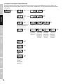
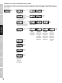
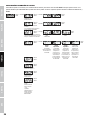
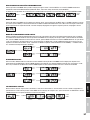
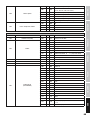
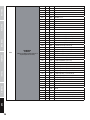
INVERTED DISPLAY
This function can be used to display letters, numbers and symbols horizontally, vertically or horizontally and vertically inverted on the LED
matrix panel. Press MODE repeatedly until “Inve” appears in the display and confirm by pressing enter. Now use UP and DOWN to select the
desired option and press ENTER to confirm.
UP/DOWN-> ENTER->
-> ENTER
<- MODE
Inversion
deactivated
Horizontal
inversion
Vertical
inversion
Horizontal and
vertical inversion

8
DMX
ITALIANO
POLSKI
ESPAÑOL
FRANCAIS
DEUTSCHENGLISH
-> ENTER ->
<- MODE
UP/DOWN
-> ENTER
<- MODE
-> ENTER ->
<- MODE
UP/DOWN
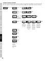
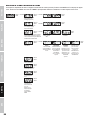
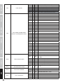
Display is rotated
by 180°
(overhead installation)
-> ENTER
<- MODE
-> ENTER ->
<- MODE
UP/DOWN
on = display permanently on
off = display goes off after ap
-
prox. 60 seconds of inactivity
-> ENTER ->
<- MODE
UP/DOWN
This menu option allows you to define
which operating mode is to be enabled if
the DMX signal is interrupted in DMX mode.
-> ENTER
<- MODE
The last DMX command
is retained
Blackout Auto programme
-> ENTER ->
<- MODE
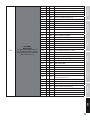
UP/DOWN
Set
dimmer curve
dimmer curve
linear
Light intensity
increases linearly
with DMX value.
dimmer curve
exponential
Light intensity can
be finely adjusted
at lower DMX
values and broadly
adjusted at higher
DMX values.
dimmer curve
logarithmic
Light intensity can
be broadly adjusted
at lower DMX values
and finely adjusted
at higher DMX
values.
-> ENTER
<- MODE
S-curve
Light intensity can
be finely adjusted
at lower and higher
DMX values and
broadly adjusted
at medium DMX
values.
-> ENTER
<- MODE
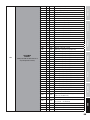
Displays
firmware version
-> ENTER
<- MODE
Displays device
temperature in °C
-> ENTER
<- MODE
Displays total
operating time in
hours
-> ENTER
<- MODE
LED test
Functional test of all
LEDs from 1 to 25.
Display flashes
during test. Press
MODE or ENTER
to stop.
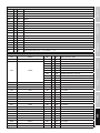
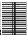
SYSTEM SETTINGS AND SYSTEM INFORMATION
To adjust system settings and access system information, press MODE repeatedly until "Sett" appears in the display. Confirm by pressing
ENTER. You can now use UP and DOWN to select and edit one of the following menu items:

9
DMX
DEUTSCHFRANCAIS
ESPAÑOL
ENGLISH
ITALIANO POLSKI
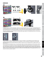
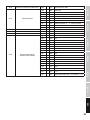
D
C
A
A
A
B
B
B
B
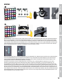
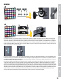
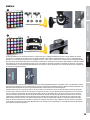
MOUNTING
Single mounting in a traverse system is carried out using either a swivel bracket (Fig. A) or two Omega mounting brackets (Fig. B). A swivel
bracket and two Omega mounting brackets are included, along with a set of screws and U-discs and the tools required (1x5 mm and 1x6
mm hexagonal tool). In both cases, ensure the brackets are firmly connected to the device, use appropriate traverse mounting bolts (not
included) and fit a suitable safety cable to the eyelet to ensure the spotlight does not fall down (safety cable not included, eyelet at rear of
device). Important: Overhead installation may only be carried out by qualified personnel.
The spotlight has an integrated connection system for mounting an unlimited number of elements horizontally and up to five elements vertically. In
order to mount a group of spotlights created in this way in a system of traverses, it is absolutely necessary to use two Omega mounting brackets
for each top element. For mechanical reasons, a group of spotlights may not be mounted on a vertical traverse.
Each element is fitted with two connecting hooks on two sides and two connecting bolts on two sides. In order to securely attach two elements,
use the 5 mm hexagonal tool to move the connecting hooks (Fig. C) into starting position (turn as far as possible to the right). Join the elements
in such a way that the two recesses in the connecting hooks (Fig. C) of one element are positioned precisely opposite the two recesses of the
connecting bolts of the other element (Fig. D). Now turn the connecting hooks anticlockwise using the hexagonal tool as far as they will go
(approx. 3/4 rotation) so that the connecting hook firmly encloses the connecting bolt. Secure each element at its eyelet by means of a suitable
safety cable (safety cable not included). For dismounting purposes, return the connecting hooks to starting position (turn right as far as they will
go). Important: Overhead installation may only be carried out by qualified personnel.

10
DMX
ITALIANO
POLSKI
ESPAÑOL
FRANCAIS
DEUTSCHENGLISH
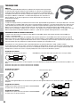
DMX TECHNOLOGY
DMX-512
DMX (Digital Multiplex) is the designation for a universal transmission protocol for
communications between corresponding devices and controllers. A DMX controller sends
DMX data to the connected DMX device(s). The DMX data is always transmitted as a serial
data stream that is forwarded from one connected device to the next via the "DMX IN" and
"DMX OUT" connectors (XLR plug-type connectors) that are found on every DMX-capable
device, provided the maximum number of devices does not exceed 32 units. The last device
in the chain needs to be equipped with a terminator (terminating resistor).
DMX CONNECTION
DMX is the common "language" via which a very wide range of types and models of equipment from various manufacturers can
be connected with one another and controlled via a central controller, provided that all of the devices and the controller are DMX
compatible. For optimum data transmission, it is necessary to keep the connecting cables between the individual devices as short as
possible. The order in which the devices are integrated in the DMX network has no influence on the addresses. Thus the device with
the DMX address 1 can be located at any position in the (serial) DMX chain: at the beginning, at the end or somewhere in the middle.
If the DMX address 1 is assigned to a device, the controller "knows" that it should send all data allocated to address 1 to this device
regardless of its position in the DMX network.
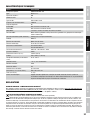
SERIAL CONNECTION OF MULTIPLE LIGHTS
1. Connect the male XLR connector (3-pin or 5-pin) of the DMX cable to the DMX output (female XLR socket) of the first DMX device
(e.g. DMX-Controller).
2. Connect the female 3-pin XLR connector of the DMX cable connected to the first projector to the DMX input (male 3-pin socket)
of the next DMX device. In the same way, connect the DMX output of this device to the DMX input of the next device and repeat until
all devices have been connected. Please note that as a rule, DMX devices are connected in series and connections cannot be shared
without active splitters. The maximum number of DMX devices in a DMX chain should not exceed 32 units.
The Adam Hall 3 STAR, 4 STAR, and 5 STAR product ranges include an extensive selection of suitable cables.
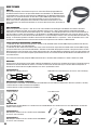
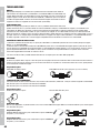
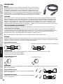
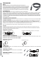
DMX CABLES
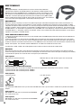
When fabricating your own cables, always observe the illustrations on this page. Never connect the shielding of the cable to the ground
contact of the plug, and always make certain that the shielding does not come into contact with the housing of the XLR plug. If the shielding
is connected to the ground, this can lead to short-circuiting and system malfunctions.
Pin Assignment
DMX cable with 3-pin XLR connectors: DMX cable with 5-pin XLR connectors (pin 4 and 5 are not used):
Shield
2
3
1
2
3
1
1
2
3
4
5
1
2
3
4
5
Shield
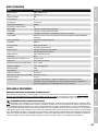
DMX TERMINATORS (TERMINATING RESISTORS)
To prevent system errors, the last device in a DMX chain needs to be equipped with a terminating resistor (120 ohm, 1/4 Watt).
3-pin XLR connector with a terminating resistor: K3DMXT3
5-pin XLR connector with a terminating resistor: K3DMXT5
Pin Assignment
3-pin XLR connector: 5-pin XLR connector:
2
3
1
1
2
3
4
5
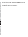
DMX ADAPTER
The combination of DMX devices with 3-pin connectors and DMX devices with 5-pin connectors in a DMX chain is possible with suitable
adapters.
Pin Assignment
DMX Adapter 5-pin XLR male to 3-pin XLR female: K3DGF0020
Pins 4 and 5 are not used.
Pin Assignment
DMX Adapter 3-pin XLR male to 5-pin XLR female: K3DHM0020
Pins 4 and 5 are not used.

11
DMX
DEUTSCHFRANCAIS
ESPAÑOL
ENGLISH
ITALIANO POLSKI
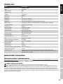
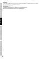
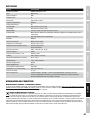
TECHNICAL DATA
Model: CLMP10WRGB
Product type: LED MATRIX PANEL
Type: 5X5 matrix
Colour spectrum: RGB
Number of LEDs: 25
LED type: 10 W Tri LED
Refresh rate: 8000 Hz
Beam angle: 40°
DMX input: 3-pin and 5-pin male XLR
DMX output: 3-pin and 5-pin female XLR
DMX mode: 3-channel, 5-channel, 19-channel, 28-channel, 78-channel
DMX functions: master dimmer, dimmer fine, auto programmes, sound programmes, stroboscope
Standalone functions: sound control, master/slave
Control system DMX512
Operating controls: mode, enter, up, down
Display elements: 4-digit LED display
Power connection: blue mains input socket
white power output socket
Operating voltage: 100-240 V AC/50-60 Hz
Power consumption: 180 W
Light intensity (@ 1 m): 6950 lx (full on)
Fuse: T3AL/250 V (5 x 20mm)
Ambient temperature (in operation): 10°C-40°C
Relative air humidity: <85%, non-condensing
Housing material: metal
Housing colour: black
Housing cooling: convection
Dimensions (W x H x D, without bracket): 580 x 580 x 125 mm
Weight (not incl. brackets): 13.7 kg
Additional features: adjustable swivel bracket including two Omega mounting brackets, safety eyelet,
integrated connection system for mounting an unlimited number of elements horizontally and
up to five elements vertically
MANUFACTURER´S DECLARATIONS
MANUFACTURER‘S WARRANTY & LIMITATIONS OF LIABILITY
You can find our current warranty conditions and limitations of liability at: https://cdn-shop.adamhall.com/media/pdf/Manufacturers-Decla-
rations-CAMEO_DE_EN_ES_FR.pdf. To request warranty service for a product, please contact Adam Hall GmbH, Daimler Straße 9,
61267 Neu Anspach / Email: [email protected] / +49 (0)6081 / 9419-0.
CORRECT DISPOSAL OF THIS PRODUCT
(valid in the European Union and other European countries with a differentiated waste collection system)
This symbol on the product, or on its documents indicates that the device may not be treated as household waste. This is to avoid
environmental damage or personal injury due to uncontrolled waste disposal. Please dispose of this product separately from other waste
and have it recycled to promote sustainable economic activity. Household users should contact either the retailer where they purchased
this product, or their local government office, for details on where and how they can recycle this item in an environmentally friendly manner.
Business users should contact their supplier and check the terms and conditions of the purchase contract. This product should not be mixed
with other commercial waste for disposal.

12
DMX
ITALIANO
POLSKI
ESPAÑOL
FRANCAIS
DEUTSCHENGLISH
FCC STATEMENT
This device complies with Part 15 of the FCC Rules. Operation is subject to the following two conditions:
(1) This device may not cause harmful interference, and
(2) This device must accept any interference received, including interference that may cause undesired operation
CE Compliance
Adam Hall GmbH states that this product meets the following guidelines (where applicable):
R&TTE (1999/5/EC) or RED (2014/53/EU) from June 2017
Low voltage directive (2014/35/EU)
EMV directive (2014/30/EU)
RoHS (2011/65/EU)
The complete declaration of conformity can be found at www.adamhall.com.
Furthermore, you may also direct your enquiry to [email protected].

13
DMX
DEUTSCHFRANCAIS
ESPAÑOL
ENGLISH
ITALIANO POLSKI
DEUTSCH
SIE HABEN DIE RICHTIGE WAHL GETROFFEN!
Dieses Gerät wurde unter hohen Qualitätsanforderungen entwickelt und gefertigt, um viele Jahre einen reibungslosen Betrieb zu gewähr-
leisten. Bitte lesen Sie diese Bedienungsanleitung sorgfältig, damit Sie Ihr neues Produkt von Cameo Light schnell und optimal einsetzen
können. Weitere Informationen über Cameo Light erhalten Sie auf unserer Website WWW.CAMEOLIGHT.COM.
SICHERHEITSHINWEISE
1. Lesen Sie diese Anleitung bitte sorgfältig durch.
2. Bewahren Sie alle Informationen und Anleitungen an einem sicheren Ort auf.
3. Befolgen Sie die Anweisungen.
4. Beachten Sie alle Warnhinweise. Entfernen Sie keine Sicherheitshinweise oder andere Informationen vom Gerät.
5. Verwenden Sie das Gerät nur in der vorgesehenen Art und Weise.
6. Verwenden Sie ausschließlich stabile und passende Stative bzw. Befestigungen (bei Festinstallationen). Stellen Sie sicher, dass Wandhalterungen
ordnungsgemäß installiert und gesichert sind. Stellen Sie sicher, dass das Gerät sicher installiert ist und nicht herunterfallen kann.
7. Beachten Sie bei der Installation die für Ihr Land geltenden Sicherheitsvorschriften.
8. Installieren und betreiben Sie das Gerät nicht in der Nähe von Heizkörpern, Wärmespeichern, Öfen oder sonstigen Wärmequellen. Sorgen
Sie dafür, dass das Gerät immer so installiert ist, dass es ausreichend gekühlt wird und nicht überhitzen kann.
9. Platzieren Sie keine Zündquellen wie z.B. brennende Kerzen auf dem Gerät.
10. Lüftungsschlitze dürfen nicht blockiert werden.
11. Das Gerät wurde ausschließlich für die Verwendung in Innenräumen entwickelt, betreiben Sie das Gerät nicht in unmittelbarer Nähe von
Wasser (gilt nicht für spezielle Outdoor Geräte - beachten Sie in diesem Fall bitte die im Folgenden vermerkten Sonderhinweise). Bringen Sie
das Gerät nicht mit brennbaren Materialien, Flüssigkeiten oder Gasen in Berührung.
12. Sorgen Sie dafür, dass kein Tropf- oder Spritzwasser in das Gerät eindringen kann. Stellen Sie keine mit Flüssigkeit gefüllten Behältnisse
wie Vasen oder Trinkgefäße auf das Gerät.
13. Sorgen Sie dafür, dass keine Gegenstände in das Gerät fallen können.
14. Betreiben Sie das Gerät nur mit dem vom Hersteller empfohlenen und vorgesehenen Zubehör.
15. Öffnen Sie das Gerät nicht und verändern Sie es nicht.
16. Überprüfen Sie nach dem Anschluss des Geräts alle Kabelwege, um Schäden oder Unfälle, z. B. durch Stolperfallen zu vermeiden.
17. Achten Sie beim Transport darauf, dass das Gerät nicht herunterfallen und dabei möglicherweise Sach- und Personenschäden verursachen kann.
18. Wenn Ihr Gerät nicht mehr ordnungsgemäß funktioniert, Flüssigkeiten oder Gegenstände in das Geräteinnere gelangt sind, oder das Gerät
anderweitig beschädigt wurde, schalten Sie es sofort aus und trennen es von der Netzsteckdose (sofern es sich um ein aktives Gerät handelt).
Dieses Gerät darf nur von autorisiertem Fachpersonal repariert werden.
19. Verwenden Sie zur Reinigung des Geräts ein trockenes Tuch.
20. Beachten Sie alle in Ihrem Land geltenden Entsorgungsgesetze. Trennen Sie bei der Entsorgung der Verpackung bitte Kunststoff und
Papier bzw. Kartonagen voneinander.
21. Kunststoffbeutel müssen außer Reichweite von Kindern aufbewahrt werden.
BEI GERÄTEN MIT NETZANSCHLUSS:
22. ACHTUNG: Wenn das Netzkabel des Geräts mit einem Schutzkontakt ausgestattet ist, muss es an einer Steckdose mit Schutzleiter
angeschlossen werden. Deaktivieren Sie niemals den Schutzleiter eines Netzkabels.
23. Schalten Sie das Gerät nicht sofort ein, wenn es starken Temperaturschwankungen ausgesetzt war (beispielsweise nach dem Transport).
Feuchtigkeit und Kondensat könnten das Gerät beschädigen. Schalten Sie das Gerät erst ein, wenn es Zimmertemperatur erreicht hat.
24. Bevor Sie das Gerät an die Steckdose anschließen, prüfen Sie zuerst, ob die Spannung und die Frequenz des Stromnetzes mit den auf
dem Gerät angegebenen Werten übereinstimmen. Verfügt das Gerät über einen Spannungswahlschalter, schließen Sie das Gerät nur an die
Steckdose an, wenn die Gerätewerte mit den Werten des Stromnetzes übereinstimmen. Wenn das mitgelieferte Netzkabel bzw. der mitgelie-
ferte Netzadapter nicht in Ihre Netzsteckdose passt, wenden Sie sich an Ihren Elektriker.
25. Treten Sie nicht auf das Netzkabel. Sorgen Sie dafür, dass spannungsführende Kabel speziell an der Netzbuchse bzw. am Netzadapter
und der Gerätebuchse nicht geknickt werden.
26. Achten Sie bei der Verkabelung des Geräts immer darauf, dass das Netzkabel bzw. der Netzadapter stets frei zugänglich ist. Trennen Sie
das Gerät stets von der Stromzuführung, wenn das Gerät nicht benutzt wird, oder Sie das Gerät reinigen möchten. Ziehen Sie Netzkabel und
Netzadapter immer am Stecker bzw. am Adapter und nicht am Kabel aus der Steckdose. Berühren Sie Netzkabel und Netzadapter niemals
mit nassen Händen.
27. Schalten Sie das Gerät möglichst nicht schnell hintereinander ein und aus, da sonst die Lebensdauer des Geräts beeinträchtigt werden könnte.
28. WICHTIGER HINWEIS: Ersetzen Sie Sicherungen ausschließlich durch Sicherungen des gleichen Typs und Wertes. Sollte eine Sicherung
wiederholt auslösen, wenden Sie sich bitte an ein autorisiertes Servicezentrum.
29. Um das Gerät vollständig vom Stromnetz zu trennen, entfernen Sie das Netzkabel bzw. den Netzadapter aus der Steckdose.
30. Wenn Ihr Gerät mit einem Volex-Netzanschluss bestückt ist, muss der passende Volex-Gerätestecker entsperrt werden, bevor er entfernt
werden kann. Das bedeutet aber auch, dass das Gerät durch ein Ziehen am Netzkabel verrutschen und herunterfallen kann, wodurch Perso-
nen verletzt werden und/oder andere Schäden auftreten können. Verlegen Sie Ihre Kabel daher immer sorgfältig.
31. Entfernen Sie Netzkabel und Netzadapter aus der Steckdose bei Gefahr eines Blitzschlags oder wenn Sie das Gerät länger nicht verwenden.
32. Das Gerät darf nur im spannungsfreien Zustand (Trennung des Netzsteckers vom Stromnetz) installiert werden.
33. Staub und andere Ablagerungen im Inneren des Geräts können es beschädigen. Das Gerät sollte je nach Umgebungsbedingungen
(Staub, Nikotin, Nebel etc.) regelmäßig von qualifiziertem Fachpersonal gewartet bzw. gesäubert werden (keine Garantieleistung),
um Überhitzung und Fehlfunktionen zu vermeiden.
34. Der Abstand zu brennbaren Materialien muss mindestens 0,5 m betragen.
35. Netzleitungen zur Spannungsversorgung mehrerer Geräte müssen mindestens 1,5 mm² Aderquerschnitt aufweisen. In der EU müssen

14
DMX
ITALIANO
POLSKI
ESPAÑOL
FRANCAIS
DEUTSCHENGLISH
die Leitungen H05VV-F, oder gleichartig, entsprechen. Geeignete Leitungen werden von Adam Hall angeboten. Mit diesen Leitungen können
Sie mehrere Geräte über den Power out Anschluss mit dem Power IN Anschluss eines weiteren Gerätes verbinden. Beachten Sie, dass die
gesamte Stromaufnahme aller angeschlossenen Geräte den vorgegebenen Wert nicht überschreitet (Aufdruck auf dem Gerät). Achten Sie
darauf, Netzleitungen so kurz wie möglich zu halten.
ACHTUNG
Entfernen Sie niemals die Abdeckung, da sonst das Risiko eines elektrischen Schlages besteht. Im
Inneren des Geräts befinden sich keine Teile, die vom Bediener repariert oder gewartet werden können.
Lassen Sie Wartung und Reparaturen ausschließlich von qualifiziertem Servicepersonal durchführen.
Das gleichseitige Dreieck mit Blitzsymbol warnt vor nichtisolierten, gefährlichen Spannungen im Geräteinneren, die einen
elektrischen Schlag verursachen können.
Das gleichseitige Dreieck mit Ausrufungszeichen kennzeichnet wichtige Bedienungs- und Wartungshinweise.
Warnung! Dieses Symbol kennzeichnet heiße Oberflächen. Während des Betriebs können bestimmte Teile des Gehäuses heiß
werden. Berühren oder transportieren Sie das Gerät nach einem Einsatz erst nach einer Abkühlzeit von mindestens 10 Minuten.
Warnung! Dieses Gerät ist für eine Nutzung bis zu einer Höhe von maximal 2000 Metern über dem Meeresspiegel bestimmt.
Warnung! Dieses Gerät ist nicht für den Einsatz in tropischen Klimazonen bestimmt.
Vorsicht! Intensive LED Lichtquelle! Gefahr der Augenschädigung. Nicht in die Lichtquelle blicken.
VORSICHT! WICHTIGE HINWEISE IN BEZUG AUF LICHT-PRODUKTE!
1. Das Produkt ist für den professionellen Einsatz im Bereich der Veranstaltungstechnik entwickelt worden und ist nicht für die Raumbeleuchtung in
Haushalten geeignet.
2. Blicken Sie niemals, auch nicht kurzzeitig, direkt in den Lichtstrahl.
3. Blicken Sie niemals mit optischen Geräten wie Vergrößerungsgläsern in den Lichtstrahl.
4. Stroboskopeffekte können unter Umständen bei empfindlichen Menschen epileptische Anfälle auslösen! Epilepsiekranke Menschen
sollten daher unbedingt Orte meiden, an denen Stroboskope eingesetzt werden.
EINFÜHRUNG
LED MATRIX PANEL 5X5 10W RGB
CLMP10WRGB
STEUERUNGSFUNKTIONEN
3-Kanal, 5-Kanal, 19-Kanal, 28-Kanal, 78-Kanal DMX-Steuerung
Master / Slave Betrieb
Standalone Funktion
EIGENSCHAFTEN
Matrix Panel mit 25 x 10W RGB LEDs. Single Pixel Kontrolle. 5 DMX-Modi. DMX-512 Steuerung. Master / Slave Betrieb. Standalone Programme.
Musiksteuerung über eingebautes Mikrofon. Safety Schrauböse und Schwenkbügel inklusive. 2 Omega-Montagebügel inklusive. Integriertes
Verbindungssystem für die Montage einer unbegrenzten Anzahl von Elementen in horizontaler Ebene und für die vertikale Montage von bis zu 5
Elementen. Betriebsspannung 100V - 240V AC / 50 - 60Hz. Leistungsaufnahme 180W.

15
DMX
DEUTSCHFRANCAIS
ESPAÑOL
ENGLISH
ITALIANO POLSKI
ANSCHLÜSSE, BEDIEN- UND ANZEIGEELEMENTE
1
POWER IN
Blaue Netzeingangsbuchse für die Spannungsversorgung des Geräts. Ein geeignetes Netzkabel befindet sich im Lieferumfang.
2
POWER OUT
Weiße Netzausgangsbuchse für die Netzversorgung weiterer CAMEO Scheinwerfer. Achten Sie darauf, dass die gesamte
Stromaufnahme aller angeschlossenen Geräte den auf dem Gerät in Ampere (A) angegebenen Wert nicht überschreitet.
3
SICHERUNGSHALTER
WICHTIGER HINWEIS: Ersetzen Sie die Sicherung ausschließlich durch eine Sicherung des gleichen Typs und mit gleichen Werten entspre-
chend des Aufdrucks auf dem Gerät! Sollte die Sicherung wiederholt auslösen, wenden Sie sich bitte an ein autorisiertes Servicezentrum.
4
POWER
Ein-/Ausschalter.
5
LED DISPLAY
Das vierstellige LED-Display zeigt die Betriebsart und weitere Systeminformationen an.
6
BEDIENTASTEN
MODE: Auswahl der Hauptmenüpunkte. In der Menüstruktur eine Ebene höher gelangen.
ENTER: Bestätigen von Programmauswahl und Wertänderungen.
UP und DOWN: Auswahl einer Betriebsart und von Systemeinstellungen, z.B. ändern von Mikrofonempfindlichkeit und DMX-Adresse.
7
MIC
Mikrofon für die Betriebsart Musiksteuerung.
8
DMX IN
Männliche 3-Pol XLR-Buchse zum Anschließen eines DMX-Kontrollgeräts (z.B. DMX-Pult).
9
DMX OUT
Weibliche 3-Pol XLR-Buchse zum Weiterleiten des DMX-Steuersignals.
10
DMX IN
Männliche 5-Pol XLR-Buchse zum Anschließen eines DMX-Kontrollgeräts (z.B. DMX-Pult).
11
DMX OUT
Weibliche 5-Pol XLR-Buchse zum Weiterleiten des DMX-Steuersignals.
12
LÜFTER
An der Geräterückseite befinden sich drei Gehäuselüfter. Achten Sie darauf, dass die Lüfter nicht abgedeckt werden und Luft ungehindert
zirkulieren kann.
2 1
3
4
7
9 8
11 10
5
6

16
DMX
ITALIANO
POLSKI
ESPAÑOL
FRANCAIS
DEUTSCHENGLISH
13
LÜFTUNGSSCHLITZE
Achten Sie darauf, dass die Lüftungsschlitze nicht abgedeckt werden und Luft ungehindert zirkulieren kann.
14
TRAGEGRIFF
Zwei Tragegriffe an der Geräterückseite erleichtern den Transport und die Montage.
15
SICHERUNGSÖSE
Eine Öse für ein Sicherungsseil befindet sich auf der Rückseite, an der Oberkante des Geräts.
Überkopfmontage darf nur von dafür ausgebildetem Personal durchgeführt werden. Der Scheinwerfer ist dabei mit einem geeigneten
Sicherungsseil an der Sicherungsöse gegen Herabfallen zu sichern.
15
13
14
12
14
13
Wenige Sekunden nach dem Einschalten ist der Scheinwerfer betriebsbereit und die Betriebsart, die zuvor angewählt war, wird aktiviert.
DMX-STARTADRESSE EINSTELLEN
Drücken Sie die MODE-Taste so oft, bis im Display „Addr“ angezeigt wird. Drücken Sie nun auf ENTER und stellen die DMX-Startadresse mit
Hilfe der Tasten UP und DOWN wunschgemäß ein (A001 - A512). Bestätigen Sie die Eingabe mit ENTER. Die synchrone Ansteuerung mehre-
rer Scheinwerfer des gleichen Modells durch ein DMX-Steuergerät (z.B. DMX-Pult) erreichen Sie, indem Sie die Scheinwerfer auf identische
DMX-Startadressen und die gleiche DMX-Betriebsart einstellen und mit Hilfe von DMX-Kabeln verbinden. Liegt kein DMX-Signal an, blinken
die Zeichen im Display, das Blinken stoppt, sobald ein DMX-Signal anliegt.
UP/DOWN
-> ENTER
<- MODE
-> ENTER->
BEDIENUNG

17
DMX
DEUTSCHFRANCAIS
ESPAÑOL
ENGLISH
ITALIANO POLSKI
DMX-BETRIEBSART EINSTELLEN
Drücken Sie die MODE-Taste so oft, bis im Display „ChAn“ angezeigt wird. Drücken Sie nun auf ENTER und wählen die gewünschte
DMX-Betriebsart mit Hilfe der Tasten UP und DOWN aus (DMX 03Ch, 05Ch, 19Ch, 28Ch, 78Ch). Bestätigen Sie die Eingabe mit ENTER.
Tabellen mit der Kanalbelegung der verschiedenen DMX-Modi finden Sie in dieser Anleitung unter DMX STEUERUNG.
UP/DOWN-> ENTER->
-> ENTER
<- MODE
SLAVE-BETRIEB
Drücken Sie die MODE-Taste so oft, bis im Display „SLAV“ angezeigt wird und bestätigen mit ENTER. Verbinden Sie die Slave- und die
Master-Einheit (gleiches Modell) mit Hilfe eines DMX-Kabels und aktivieren in der Master-Einheit die Standalone Betriebsart Musiksteuerung.
Nun folgt die Slave-Einheit der Master-Einheit. Liegt kein Steuer-Signal an, blinken die Zeichen im Display, das Blinken stoppt, sobald ein
Steuer-Signal anliegt.
BETRIEBSART MUSIKSTEUERUNG
Aktivieren Sie die Betriebsart Musiksteuerung, um den Scheinwerfer über das integrierte Mikrofon steuern zu lassen (Bassimpulse) und stellen
die Mikrofonempfindlichkeit wunschgemäß ein. Drücken Sie die MODE-Taste so oft, bis im Display „SoUn“ angezeigt wird und bestätigen mit
ENTER. Wählen Sie nun mit Hilfe der Tasten UP und DOWN den Menüpunkt „Soun“, drücken auf ENTER und wählen wiederum mit Hilfe der
Tasten UP und DOWN „on“ zum Aktivieren und „oFF“ zum Deaktivieren der Musiksteuerung aus und bestätigen mit ENTER. Wählen Sie nun den
Menüpunkt für die Einstellung der Mikrofonempfindlichkeit „SenS“ mit Hilfe der Tasten UP und DOWN aus, bestätigen mit ENTER und stellen
den gewünschten Wert mit UP und DOWN ein (1 = minimale Empfindlichkeit, 99 = maximale Empfindlichkeit). Bestätigen Sie mit ENTER.
UP/DOWN-> ENTER->
-> ENTER ->
<- MODE
UP/DOWN
-> ENTER
<- MODE
-> ENTER ->
<- MODE
UP/DOWN
-> ENTER
<- MODE
FARBBALANCE
Betriebsartübergreifende Kalibrierung der Farbwiedergabe bei Mischfarben. Drücken Sie die MODE-Taste so oft, bis im Display „baLa“ angezeigt
wird und bestätigen mit ENTER. Wählen Sie nun die Farbe, deren Intensität Sie verändern wollen, mit Hilfe der Tasten UP und DOWN aus (red = Rot,
Gree = Grün, bLue = Blau) und bestätigen mit ENTER. Die Farbintensität stellen Sie wiederum mit Hilfe von UP und DOWN von 0 bis 255 ein und
bestätigen mit ENTER.
UP/DOWN-> ENTER->
-> ENTER ->
<- MODE
UP/DOWN
-> ENTER
<- MODE
-> ENTER ->
<- MODE
UP/DOWN
-> ENTER
<- MODE
-> ENTER ->
<- MODE
UP/DOWN
-> ENTER
<- MODE
GESPIEGELTE DARSTELLUNG
Mit Hilfe dieser Funktion können auf dem LED Matrix Panel dargestellte Buchstaben, Zahlen und Symbole horizontal, vertikal oder horizontal
und vertikal gespiegelt werden. Drücken Sie die MODE-Taste so oft, bis im Display „Inve““ angezeigt wird und bestätigen mit ENTER.
Wählen Sie nun die gewünschte Option mit Hilfe der Tasten UP und DOWN aus und bestätigen mit ENTER.
UP/DOWN-> ENTER->
-> ENTER
<- MODE
Spiegelung
deaktiviert
horizontale
Spiegelung
vertikale
Spiegelung
horizontale und
vertikale Spiegelung

18
DMX
ITALIANO
POLSKI
ESPAÑOL
FRANCAIS
DEUTSCHENGLISH
-> ENTER ->
<- MODE
UP/DOWN
-> ENTER
<- MODE
-> ENTER ->
<- MODE
UP/DOWN
Display-Anzeige wird um
180° bedreht
(Überkopfmontage)
-> ENTER
<- MODE
-> ENTER ->
<- MODE
UP/DOWN
on = Display permanent an
off = Display erlischt nach
ca. 60 Sekunden Inaktivität
-> ENTER ->
<- MODE
UP/DOWN
Mit Hilfe dieses Menüpunkts definieren Sie,
welcher Betriebszustand aktiviert werden
soll, wenn in der DMX-Betriebsart das
DMX-Signal unterbrochen wird.
-> ENTER
<- MODE
Letzter DMX-Befehl
wird gehalten
Blackout Auto-Programm
-> ENTER ->
<- MODE
UP/DOWN
Einstellen der
Dimmer-Kurve
Dimmer-Kurve
linear
Die Lichtintensität
steigt linear mit dem
DMX-Wert an.
Dimmer-Kurve
exponentiell
Die Lichtintensität
lässt sich im unter
-
en DMX-Wertbereich
fein und im oberen
DMX-Wertbereich
grob einstellen
Dimmer-Kurve
logarithmisch
Die Lichtintensität
lässt sich im unter
-
en DMX-Wertbereich
grob und im oberen
DMX-Wertbereich
fein einstellen.
-> ENTER
<- MODE
S-Kurve
Die Lichtintensität
lässt sich im
unteren und oberen
DMX-Wertbereich
fein und im mittler
-
en DMX-Wertbereich
grob einstellen.
-> ENTER
<- MODE
Anzeige der
Firmware Version
-> ENTER
<- MODE
Anzeige der Geräte-
temperatur in °C
-> ENTER
<- MODE
Anzeige der
Betriebszeit in
Stunden
-> ENTER
<- MODE
LED Test
Funktionstest aller
LEDs von 1 bis 25.
Display blinkt
während Test. Zum
Beenden MODE oder
ENTER drücken.
SYSTEMEINSTELLUNGEN UND SYSTEMINFORMATIONEN
Um Systemeinstellungen vorzunehmen und Systeminformationen auszulesen, drücken Sie die MODE-Taste so oft, bis im Display „Sett“
angezeigt wird. Bestätigen Sie mit ENTER. Sie können nun mit Hilfe der UP und DOWN Tasten einen der folgenden Menüpunkte auswählen
und bearbeiten:

19
DMX
DEUTSCHFRANCAIS
ESPAÑOL
ENGLISH
ITALIANO POLSKI
MONTAGE
D
C
A
A
A
B
B
B
B
Die Einzelmontage in einem Traversensystem erfolgt entweder mit Hilfe eines Schwenkbügels (Abb. A), oder zweier Omega-Montagebügel
(Abb. B). Ein Schwenkbügel und zwei Omega-Montagebügel befinden sich im Lieferumfang, ebenso ein Satz Schrauben und U-Scheiben,
sowie geeignetes Werkzeug (1x 5mm und 1x 6mm Sechskant-Werkzeug). Sorgen Sie in beiden Fällen für eine feste Verbindung am Gerät,
nutzen geeignete Traversenklemmen für die Montage (nicht im Lieferumfang enthalten) und sichern es gegen Herabfallen mit einem geeig-
neten Sicherungsseil an der Sicherungsöse (Sicherungsseil nicht im Lieferumfang enthalten, Sicherungsöse auf der Rückseite). Wichtiger
Hinweis: Überkopfmontage darf nur von dafür ausgebildetem Personal durchgeführt werden.
Der Scheinwerfer verfügt über ein integriertes Verbindungssystem für die Montage einer unbegrenzten Anzahl von Elementen in horizontaler Ebene
und für die vertikale Montage von bis zu 5 Elementen. Für die Montage einer so entstandenen Scheinwerfer-Gruppe in einem Traversensystem
müssen zwingend zwei Omega-Montagebügel pro oberstes Element zum Einsatz kommen. Die Montage einer Scheinwerfer-Gruppe an einer
vertikal geführten Traverse ist aus mechanischen Gründen nicht zulässig.
Zwei Seiten eines Elements sind mit je 2 Verbindungshaken und zwei Seiten mit je 2 Verbindungsbolzen ausgestattet. Für eine sichere
Verbindung zweier Elemente bringen Sie die Verbindungshaken (Abb. C) mit Hilfe des mitgelieferten 5mm Sechskant-Werkzeugs in die
Ausgangsposition im Gehäuse (Drehung nach rechts bis zum Anschlag). Fügen Sie die zu verbindenden Elemente in der Art zusammen, dass
die beiden Aussparungen der Verbindungshaken (Abb. C) des einen und die beiden Aussparungen der Verbindungsbolzen (Abb. D) des anderen
Elements exakt gegenüberliegen. Drehen Sie nun die Verbindungshaken mit Hilfe des Sechskant-Werkzeugs gegen den Uhrzeigersinn bis zum
Anschlag nach links (ca. 3/4 Umdrehung), damit der Verbindungshaken den Verbindungsbolzen fest umschließt. Sichern Sie jedes Element mit
einem geeigneten Sicherungsseil an seiner Sicherungsöse (Sicherungsseil nicht im Lieferumfang enthalten). Zum Lösen der Verbindung bringen
Sie die Verbindungshaken in die Ausgangsposition (Drehung nach rechts bis zum Anschlag). Wichtiger Hinweis: Überkopfmontage darf nur von
dafür ausgebildetem Personal durchgeführt werden.

20
DMX
ITALIANO
POLSKI
ESPAÑOL
FRANCAIS
DEUTSCHENGLISH
DMX TECHNIK
DMX-512
DMX (Digital Multiplex) ist die Bezeichnung für ein universelles Übertragungsprotokoll für
die Kommunikation zwischen entsprechenden Geräten und Controllern. Ein DMX-Controller
sendet DMX-Daten an das/die angeschlossene(n) DMX-Gerät(e). Die DMX-Datenübertragung
erfolgt stets als serieller Datenstrom, der über die an jedem DMX-fähigen Gerät vorhandenen
DMX IN- und DMX OUT-Anschlüsse (XLR-Steckverbinder) von einem angeschlossenen
Gerät an das nächste weitergeleitet wird, wobei die maximale Anzahl der Geräte 32 nicht
überschreiten darf. Das letzte Gerät der Kette ist mit einem Abschlussstecker (Terminator) zu
bestücken.
DMX-VERBINDUNG:
DMX ist die gemeinsame "Sprache", über die sich die unterschiedlichsten Gerätetypen und Modelle verschiedener Hersteller
miteinander verkoppeln und über einen zentralen Controller steuern lassen, sofern sämtliche Geräte und der Controller DMX-
kompatibel sind. Für eine optimale Datenübertragung ist es erforderlich, die Verbindungskabel zwischen den einzelnen Geräten so
kurz wie möglich zu halten. Die Reihenfolge, in der die Geräte in das DMX-Netzwerk eingebunden sind, hat keinen Einfluss auf die
Adressierung. So kann sich das Gerät mit der DMX-Adresse 1 an einer beliebigen Position in der (seriellen) DMX-Kette befinden, am
Anfang, am Ende oder irgendwo in der Mitte. Wird einem Gerät die DMX-Adresse 1 zugewiesen, "weiß" der Controller, dass er alle
der Adresse 1 zugeordneten Daten an dieses Gerät senden soll, ungeachtet seiner Position im DMX-Verbund.
SERIELLE VERKOPPLUNG MEHRERER SCHEINWERFER
1. Verbinden Sie den männlichen XLR-Stecker (3-Pol oder 5-Pol) des DMX-Kabels mit dem DMX-Ausgang (weibliche XLR-Buchse)
des ersten DMX-Geräts (z.B. DMX-Controller).
2. Verbinden Sie den weibliche XLR-Stecker des an den ersten Scheinwerfer angeschlossenen DMX-Kabels mit dem DMX-Eingang
(männliche XLR-Buchse) des nächsten DMX-Geräts. Verbinden Sie den DMX-Ausgang dieses Geräts in der gleichen Weise mit dem
DMX-Eingang des nächsten Geräts und so weiter. Bitte beachten Sie, dass DMX-Geräte grundsätzlich seriell verschaltet werden und
die Verbindungen nicht ohne aktiven Splitter geteilt werden können. Die maximale Anzahl der DMX-Geräte einer DMX-Kette darf 32
nicht überschreiten.
Eine umfangreiche Auswahl geeigneter DMX-Kabel finden Sie in den Adam Hall Produktlinien 3 STAR, 4 STAR und 5 STAR.
DMX-KABEL:
Beachten Sie bei der Anfertigung eigener Kabel unbedingt die Abbildungen auf dieser Seite. Verbinden Sie auf keinen Fall die Abschirmung
des Kabels mit dem Massekontakt des Steckers, und achten Sie darauf, dass die Abschirmung nicht mit dem XLR-Steckergehäuse in
Kontakt kommt. Hat die Abschirmung Massekontakt, kann dies zu Systemfehlern führen.
Steckerbelegung:
DMX-Kabel mit 3-Pol XLR-Steckern: DMX-Kabel mit 5-Pol XLR-Steckern (Pin 4 und 5 sind nicht belegt.):
Shield
2
3
1
2
3
1
1
2
3
4
5
1
2
3
4
5
Shield
DMX-ABSCHLUSSSTECKER (TERMINATOR):
Um Systemfehler zu vermeiden, ist das letzte Gerät einer DMX-Kette mit einem Abschlusswiderstand zu bestücken (120 Ohm, 1/4 Watt).
3-Pol XLR-Stecker mit Abschlusswiderstand: K3DMXT3
5-Pol XLR-Stecker mit Abschlusswiderstand: K3DMXT5
Steckerbelegung:
3-Pol XLR-Stecker: 5-Pol XLR-Stecker:
2
3
1
1
2
3
4
5
DMX-ADAPTER:
Die Kombination von DMX-Geräten mit 3-Pol Anschlüssen und DMX-Geräten mit 5-Pol Anschlüssen in einer DMX-Kette ist mit Hilfe von
Adaptern ebenso möglich.
Steckerbelegung
DMX-Adapter 5-Pol XLR male auf 3-Pol XLR female: K3DGF0020
Pin 4 und 5 sind nicht belegt.
Steckerbelegung
DMX-Adapter 3-Pol XLR male auf 5-Pol XLR female: K3DHM0020
Pin 4 und 5 sind nicht belegt.
La page est en cours de chargement...
La page est en cours de chargement...
La page est en cours de chargement...
La page est en cours de chargement...
La page est en cours de chargement...
La page est en cours de chargement...
La page est en cours de chargement...
La page est en cours de chargement...
La page est en cours de chargement...
La page est en cours de chargement...
La page est en cours de chargement...
La page est en cours de chargement...
La page est en cours de chargement...
La page est en cours de chargement...
La page est en cours de chargement...
La page est en cours de chargement...
La page est en cours de chargement...
La page est en cours de chargement...
La page est en cours de chargement...
La page est en cours de chargement...
La page est en cours de chargement...
La page est en cours de chargement...
La page est en cours de chargement...
La page est en cours de chargement...
La page est en cours de chargement...
La page est en cours de chargement...
La page est en cours de chargement...
La page est en cours de chargement...
La page est en cours de chargement...
La page est en cours de chargement...
La page est en cours de chargement...
La page est en cours de chargement...
La page est en cours de chargement...
La page est en cours de chargement...
La page est en cours de chargement...
La page est en cours de chargement...
La page est en cours de chargement...
La page est en cours de chargement...
La page est en cours de chargement...
La page est en cours de chargement...
La page est en cours de chargement...
La page est en cours de chargement...
La page est en cours de chargement...
La page est en cours de chargement...
La page est en cours de chargement...
La page est en cours de chargement...
La page est en cours de chargement...
La page est en cours de chargement...
La page est en cours de chargement...
La page est en cours de chargement...
La page est en cours de chargement...
La page est en cours de chargement...
La page est en cours de chargement...
La page est en cours de chargement...
La page est en cours de chargement...
La page est en cours de chargement...
-
 1
1
-
 2
2
-
 3
3
-
 4
4
-
 5
5
-
 6
6
-
 7
7
-
 8
8
-
 9
9
-
 10
10
-
 11
11
-
 12
12
-
 13
13
-
 14
14
-
 15
15
-
 16
16
-
 17
17
-
 18
18
-
 19
19
-
 20
20
-
 21
21
-
 22
22
-
 23
23
-
 24
24
-
 25
25
-
 26
26
-
 27
27
-
 28
28
-
 29
29
-
 30
30
-
 31
31
-
 32
32
-
 33
33
-
 34
34
-
 35
35
-
 36
36
-
 37
37
-
 38
38
-
 39
39
-
 40
40
-
 41
41
-
 42
42
-
 43
43
-
 44
44
-
 45
45
-
 46
46
-
 47
47
-
 48
48
-
 49
49
-
 50
50
-
 51
51
-
 52
52
-
 53
53
-
 54
54
-
 55
55
-
 56
56
-
 57
57
-
 58
58
-
 59
59
-
 60
60
-
 61
61
-
 62
62
-
 63
63
-
 64
64
-
 65
65
-
 66
66
-
 67
67
-
 68
68
-
 69
69
-
 70
70
-
 71
71
-
 72
72
-
 73
73
-
 74
74
-
 75
75
-
 76
76


Cameo CLMP10WRGB Manuel utilisateur
- Catégorie
- Projecteurs
- Taper
- Manuel utilisateur
- Ce manuel convient également à
dans d''autres langues
- italiano: Cameo CLMP10WRGB Manuale utente
- español: Cameo CLMP10WRGB Manual de usuario
- Deutsch: Cameo CLMP10WRGB Benutzerhandbuch
- polski: Cameo CLMP10WRGB Instrukcja obsługi
Documents connexes
-
Cameo Q-Spot 40 TW Black Manuel utilisateur
-
-
Cameo Flash Matrix 250 Le manuel du propriétaire
-
-
-
-
-
-
-
Cameo ROTOFEVER CLRF Manuel utilisateur
