
ASD-711i/712i
Guide to Installation and Operation
Notice d'installation et d'utilisation
M301-9920-100
Copyright 2000 Miranda Europe
Specification may be subject to change
Printed in France
May 00
Copyright 2000 Miranda Europe
Les spécifications peuvent être modifiées sans préavis
Imprimé en France
mai 00
ASD-711i/712i


ASDASD--711i/712i711i/712i
3
Guide to installation & Operation
1 General............................................................................................5
1.1 Introduction ................................................................................5
1.2 Features .....................................................................................5
2 Installation......................................................................................6
2.1 Unpacking ..................................................................................6
2.2 Mechanical installation..............................................................6
2.2.1 imaging Quartet series trays ..................................................................... 6
2.2.2 imaging Symphonie Housing Frame ........................................................ 7
2.3 Rear Panel Label.......................................................................8
2.3.1 Quartet Frame............................................................................................ 8
2.3.2 Symphonie Frame ..................................................................................... 8
2.4 Electrical installation..................................................................9
2.4.1 110 Ω rear panel........................................................................................ 9
2.4.2 75 Ω rear panel.......................................................................................... 9
2.4.3 Pin assignment ........................................................................................10
2.5 Applications ..............................................................................11
2.5.1 Input connections.....................................................................................11
2.5.2 Output connections..................................................................................11
2.5.3 Synchronization .......................................................................................11
2.5.4 0dBFS.......................................................................................................12
2.5.5 GPI Outputs .............................................................................................12
3 Operation......................................................................................13
3.1 ASD-711i or ASD-712i user interface....................................13
3.2 Configurations and adjustments.............................................14
3.2.1 Jumper and switches location.................................................................14
3.2.2 Configuration............................................................................................15
3.3 Menu introduction ....................................................................16
3.4 Menu organization...................................................................17
3.5 Menu LVL .................................................................................18
3.6 Menu DITH...............................................................................18
3.7 Menu MUTE .............................................................................18
3.8 Menu TEST ..............................................................................19
3.9 Menu REF ................................................................................19
3.10 Menu FREQ .............................................................................20
3.11 Menu AES ................................................................................20
3.12 Menu ORIG ..............................................................................21
3.13 Menu DEST..............................................................................21
3.14 Menu ALRM .............................................................................22
3.15 Menu FACT..............................................................................22
4 Technical Specifications...........................................................23

ASDASD--711i/712i711i/712i
4
Notice d'installation et d'utilisation
1 Généralités...................................................................................25
1.1 Introduction ..............................................................................25
1.2 Caractéristiques.......................................................................25
2 Installation....................................................................................26
2.1 Livraison...................................................................................26
2.2 Installation mécanique ............................................................26
2.2.1 Installation en coffret Quartet..................................................................26
2.2.2 Installation en châssis Symphonie .........................................................27
2.3 Le lexan d'identification...........................................................28
2.3.1 Châssis Quartet.......................................................................................28
2.3.2 Châssis Symphonie.................................................................................28
2.4 Installation électrique...............................................................29
2.4.1 Face arrière A110 Ω................................................................................29
2.4.2 Face arrière 75 Ω.....................................................................................29
2.4.3 Affectation connecteurs...........................................................................30
2.5 Applications ..............................................................................31
2.5.1 Raccordement des entrées.....................................................................31
2.5.2 Raccordement des sorties ......................................................................31
2.5.3 Synchronisation .......................................................................................31
2.5.4 0 dBFS .....................................................................................................32
2.5.5 Les sorties GPI ........................................................................................32
3 Exploitation..................................................................................33
3.1 Présentation des composants de face avant ........................33
3.2 Configuration et réglages ..........................................................34
3.2.1 Localisation des cavaliers et des switches.............................................34
3.2.2 Configuration............................................................................................35
3.3 Introduction aux Menus...........................................................36
3.4 Architecture des menus ..........................................................37
3.5 Menu LVL .................................................................................38
3.6 Menu DITH...............................................................................38
3.7 Menu MUTE .............................................................................39
3.8 Menu TEST ..............................................................................39
3.9 Menu REF ................................................................................40
3.10 Menu FREQ .............................................................................40
3.11 Menu AES ................................................................................40
3.12 Menu ORIG ..............................................................................41
3.13 Menu DEST..............................................................................41
3.14 Menu ALRM .............................................................................42
3.15 Menu FACT..............................................................................42
4 Spécifications..............................................................................43
Appendix - Annexe...............................................................................45

ASDASD--711i/712i711i/712i
5
1 General
1.1 Introduction
The ASD-711i is a high quality, 24-bit Analog to digital audio converter that allows conversion of
a stereo Analog audio signal to an AES/EBU type digital signal. The dual version, ASD-712i, is
fitted with two independent converters. The sampling rate can be set up to 96 kHz by an internal
clock, or by using an external reference signal. The internal digital EBU tone generator, enabled
from the card edge, facilitates alignment of audio levels. User set channel identification data may
be encoded in the AES/EBU status bits. The ASD-711i and ASD-712i are compatible with AES3
110 Ω balanced and AES3-id 75 Ω unbalanced audio standards.
1.2 Features
• 24-bit high-quality Analog to digital audio conversion
• 96 kHz, 48 kHz, 44.1 kHz and 32kHz sampling rate
• Level adjustment: -96 to +31.5 dB (0.5 dB steps)
• Auto detect reference input: NTSC, PAL, AES3 or Word Clock
• User coding of channel status bits
• Internal EBU tone generator
• Internal AES silence generator
• 8 values for 0 dBFS: +28/+24/+22/+21/+20/+18/+16/+15 dBu
• 2 (or 4) balanced audio inputs
• AES3 (110 Ω) or AES3-id (75 Ω) outputs
• 4 GPI outputs

ASDASD--711i/712i711i/712i
6
2 Installation
2.1 Unpacking
Make sure the following have been shipped with your ASD-711i or ASD-712i. If any of the
following items are missing, contact your distributor or Miranda Europe.
• ASD-711i or ASD-712i
• ASD-711i or ASD-712i rear panel labels
2.2 Mechanical installation
The ASD-711i or ASD-712i must be mounted within Quartet-A75 or-A110 tray or in Symphonie
R-A75 or R-A110 in order to provide power to the card.
This section describes how to install the ASD-711i or ASD-712i in any of these trays. It is not
necessary to switch off the power from these trays when installing the ASD-711i or ASD-712i
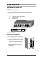
2.2.1 imaging Quartet series trays
To install this card into Quartet-A75 or Quartet-A110 follow these steps. For a closer look at card
installation and removal, refer to the tray's technical manual.
1. Remove the tray's front panel by rotating the thumbscrews counter clockwise. Pull
on the handles.
2. Select an empty slot
3. Carefully place the ASD-711i or ASD-712i between a set of card guides and gently
push the card towards the rear of the tray until the card edge connector is secured
to the back plane. The card's edge connector having 96 points, it may be
necessary to push lightly when connecting the two connectors. Pull lightly on the
card verifying that it does not move.
4. Replace the tray's front panel. Make sure to rotate the thumbscrews clockwise in
order to secure it to the chassis.

ASDASD--711i/712i711i/712i
7
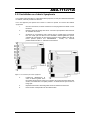
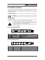
2.2.2 imaging Symphonie Housing Frame
It is not necessary to switch off the power when installing or removing a module from/to
Symphonie. To install a module, follow these steps. For a closer look at card installation and
removal, refer to the housing frame's Guide to Installation and Operation.
1. Open the front panel door by pulling on the door handles and gently lowering it.
2. Unscrew the bar.
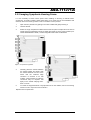
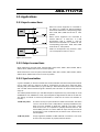
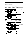
3. Select an empty compartment. Make sure that the rear panel corresponds to the card to
install, and that configuration jumper of 5 BNC rear panel are in the proper position (LK1
switch: REFERENCE: LOCAL). A bad configuration will induce a malfunction.
Figure 1: rear panels for Symphonie
4. Carefully place the module between
the module guides and slowly push
the module towards the rear of the
frame until the module's edge
connector is secured to its rear
module. A light pressure to mate the
connectors may be required. Pull
lightly on the module verifying that it
does not move.
5. To install the Symphonie-R-M or Symphonie-R-A-75 rear module, refer to the housing
frame's Guide to Operation and Installation.
Replace the front panel door.

ASDASD--711i/712i711i/712i
8
2.3 Rear Panel Label
2.3.1 Quartet Frame
A connector label has been shipped with your ASD-711i or ASD-712i. This label is to be
connected on the Quartet tray rear panel in order to identify the ASD-711i or ASD-712i external
connectors. ASD-711i corresponds to only channel 1; ASD-712i corresponds to channel 1 and 2.
The-rear panel is always equipped with ASD-712i rear panel.
1. To install the label, follow these steps
2. On the tray's rear panel, locate the ASD-711i or ASD-712i connectors
3. Remove the screws as shown in the following diagram
4. Carefully, apply the label to the connectors
5. Replace the screws making sure not to damage the label.
Figure 2: Example of label installation
2.3.2 Symphonie Frame
To install the Symphonie label, follow these steps
while referring to Figure below
1. On Symphonie’s rear panel, locate the
appropriate connectors.
2. Remove the rear label mounting screws
from the rear module.
3. Carefully apply the label to the connectors
making sure the label’s text is read from
top to bottom.
4. Replace the screws making sure not to
damage the label.
Figure 3: Symphonie rear panel label installation
ReferenceMODULE LABEL ORIENTATIONMODULE 1

ASDASD--711i/712i711i/712i
9
2.4 Electrical installation
When connecting the ASD-711i or ASD-712i to external equipment, make sure that all digital
connections are point-to-point.
Refer to the figure below and to the following descriptions for a complete ASD-711i or ASD-712i
installation.
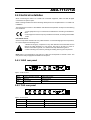
This equipment is conform to the CEE 89 / 336 directive and operation is subject to the following
two conditions:
1- This equipment may not cause harmful interference according to EN 50081-1
rules.
2- This equipment must accept any interference received, according to EN 50082-
1 rules.
Precaution of use:
Several components included are very static-sensitive. To avoid damaging those components,
be sure to respect the following rules:
1- Before touching any component or any other element of the card make sure to
reduce any static electricity on your person. One way to do this is to touch a
surface connected to ground, or to wear a wrist strap attached to ground.
2- When handling card, hold it by the edges avoiding touching the components.
Note: ASD-711i corresponds to only channel 1; ASD-712i corresponds to channel 1 and 2. The
rear panel is always equipped with ASD-712i rear panel.
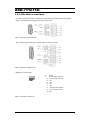
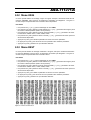
2.4.1 110 ΩΩ rear panel
Figure 4: 110 Ω rear panel
AES 26 point HD Sub-D socket Digital audio outputs and AES3 reference input
ANLG 15 point HD Sub-D socket Analog audio inputs
REF.IN BNC jack Reference input
REM RJ10 socket GPI outputs
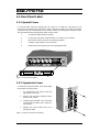
2.4.2 75 ΩΩ rear panel
Figure 5: 75 Ω rear panel
OUT1, OUT2 BNC jacks Digital audio outputs
REF.IN BNC jack Reference input
ANLG 15 point HD Sub-D socket Analog audio inputs
REM RJ10 socket GPI outputs

ASDASD--711i/712i711i/712i
10
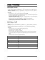
2.4.3 Pin assignment
ASD-711i corresponds to channel 1only; ASD-712i corresponds to channel 1 and 2.
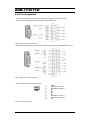
ANLG (15 points high density D-SUB socket): Analog Audio Inputs:
Figure 6: Analog audio input pin assignment
AES (26 points high density D-SUB socket): Digital Audio Outputs and AES3 Reference input
Figure 7: Digital audio output pin assignment
REM (10 points RJ10socket): GPI outputs
1: GND
2: ERROR OUT LEFT 1
3: ERROR OUT RIGHT 1
4: NC
5: NC
6: NC
7: NC
8: ERROR OUT LEFT 2
9: ERROR OUT RIGHT 2
10: NC
Figure 8: Remote pin assignment

ASDASD--711i/712i711i/712i
11
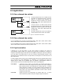
2.5 Applications
2.5.1 Input connections
When one source equipment is connected to
one ASD-711i or ASD-712i, 600 Ω termination
load can be selected: the corresponding jumper
IN1L, IN1R, IN2L, IN2R must be set on "ON"
position.
When source equipment are connected to
several ASD-711i or ASD-712i, if a 600
Ω termination load is needed, it must be
selected on the last ASD-711i or ASD-712i. The
corresponding jumper IN1L, IN1R, IN2L, IN2R
must be set on "ON" position.
ASD-711i corresponds to only channel 1; ASD-
712i corresponds to channel 1 and 2.
Figure 9: Input connections
2.5.2 Output connections
When used with a 75 Ω rear panel, switches SW1, SW2, SW11, SW21, SW12, SW22, SW13,
SW23, SW14, SW24 must be set on the A75 position.
When used with a 110 Ω rear panel, switches SW1, SW2, SW11, SW21, SW12, SW22, SW13,
SW23, SW14, SW24 must be set on the A110 position.
2.5.3 Synchronization
A green Led (REF) on the front-end side of the board indicates when lit that the present external
sync is valid. If the sync signal is an AES or a Wordclock, the user has to select the same
sampling rate (in the FREQ menu) to get a valid sync. When the external sync mode is selected
and non-valid external reference signal is detected, this Led blinks. In external mode, the Led
stays off.
The relative phase between sync and AES samples is respected for any case except for mode
VIDEO/NTSC. For VIDEO/PAL mode, output samples are aligned with the start of the first line.
The setting of internal or external synchronization is made via the user's front interface or
remotely.
110 ΩΩ rear panel The AES 110 Ω sync input is located on "AES" D-Sub socket. The switch
“LD110” must be set on the 110Ω position to properly terminate the line.
Other syncs are available on BNC jack "REF.IN". The switch “LD75”
must be set on the 75 Ω position to properly terminate the line. The
second BNC jack "N/C" is lined to "REF.IN" input and may be used as
loop-through. For this conditional use, the switch “LD75” must be set on
the HIZ position.
75 ΩΩ rear panel All sync signal are available on BNC "REF.IN". The switch “LD75” must
be set on the 75 Ω position to properly terminate the line.

ASDASD--711i/712i711i/712i
12
2.5.4 0dBFS
The three switches “SW3”, “SW4” and “SW5” set the RMS value of sine wave to obtain 0dBFS
for a level adjustment set to 0dB.
2.5.5 GPI Outputs
Four open-collector GPI outputs (one for each channel) are available on the REM socket. No
current flows through one output pin when the corresponding Led is OFF (Analog signal present)
and each output sinks current if the Led is ON (absence signal or overload).
These outputs are inactive when the alarm are disabled (ALRM menu, OFF selection).

ASDASD--711i/712i711i/712i
13
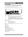
3 Operation
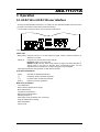
3.1 ASD-711i or ASD-712i user interface
The Figure below illustrates the ASD-711i or ASD-712i user interface situated at the front end of
the card. The interface components include the following:
For information on these controls, refer to the rest of this section
Figure 10: ASD-711i or ASD-712i user interface
Status Leds
REF (green) indicates presence of a valid reference signal, blinks if external reference is
selected or not valid.
INPUT1/2 one green and one red led for each channel
Presence signal L & R (green led)
Default L & R (red led). These Leds indicate no signal has been detected on
Analog inputs in the last 15 seconds when corresponding green Led are
extinguished or Overload when corresponding green Led are lighted.
TEST (yellow)indicates tone generator or AES silence selected
Front panel pushbuttons
[ SEL]: Activates the displayed parameter
[ -]: Decreases value of selected parameter
[ + ]: Increases value of selected parameter
[ ESC ): Returns to previous parameter
Main menu parameters
Level adjustment
Dither insertion (Output Word Length)
Mute (AES silence)
Test (AES tone generator)
Reference (synchronization)
Sampling Frequency
AES coding mode (Professional or Consumer)
Origin and destination message
Alarm deactivation
Factory reset

ASDASD--711i/712i711i/712i
14
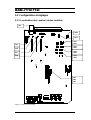
3.2 Configurations and adjustments
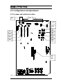
3.2.1 Jumper and switches location
Figure 11: Switches location
LD110
LD75
SW2 SW1
SW21
SW11
SW22
SW12
SW23
SW13
SW24
SW14
IN2L
IN2R
IN1L
IN1R
SW3
SW4
SW5

ASDASD--711i/712i711i/712i
15
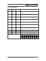
3.2.2 Configuration
Switch
Channel
1
Switch
Channel
2
Position Designation
SW1 SW2 A75 Rear panel selection (75 or 110 Ω)
A110
SW11 SW21 A75 Rear panel selection (75 or 110 Ω)
A110
SW12 SW22 A75 Rear panel selection (75 or 110 Ω)
A110
SW13 SW23 A75 Rear panel selection (75 or 110 Ω)
A110
SW14 SW24 A75 Rear panel selection (75 or 110 Ω)
A110
LD75 75 Ω
75 Ω termination for a video or word clock reference
signal
HIZ
LD110 110 Ω 110 Ω termination for an AES3 reference signal
HIZ
IN1L IN2L ON Internal 600 Ω load on Analog left input
IN1R IN2R ON Internal 600 Ω load on Analog right input
J4, J5, J6 Spare jumpers
0dBFS: Selects the 0 dBFS value
+15 +16 +18 +20 +21 +22 +24 +28
SW3 ON OFF ON OFF ON OFF ON OFF
SW4 ON ON OFF OFF ON ON OFF OFF
SW3, SW4, SW5
SW ON ON ON ON OFF OFF OFF OFF

ASDASD--711i/712i711i/712i
16
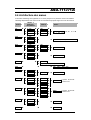
3.3 Menu introduction
Most ASD-711i or ASD-712i parameters are accessed and changed via an easy-to-use menu.
The flow chart of figure below outlines the entire ASD-711i or ASD-712i menu path. Each menu is
described throughout this section. The follow items should be remembered when accessing the
menu.
Automatic display turn off after 1-minute interval
If the menu is currently being accessed and no push-button has been pressed for 1 minute, the
ASD-711i or ASD-712i automatically turns off the display. A press on any push button [ + ], [ - ] or
[ SEL ] will turn on the display without any change on the current parameter.
Navigating through the menu
The front panel push buttons are used to navigate the menu. The following describes the function
of each push-button when navigating through the menu.
[ + ] Press [ + ] to move down in the menu or to increase the parameter value. For
example, if you are currently at I-1&2, pressing [ + ] will scroll downwards
through the selections I-1 and I-2.
Depressing [ + ] during an adjustment will increase the parameter value at faster
rate.
[ - ] Press [ - ] to move up in the menu or to decrease the parameter value. For
example, if you are currently at FREQ, pressing [ - ] will scroll through the
selections REF, TEST, MUTE and DITH.
Depressing [ - ] during an adjustment will decrease the parameter value at faster
rate.
[ SEL ] Changes to a menu parameter are stored immediately to non-volatile memory.
For example, after the L gain value has been set, press [ SEL] and the new
value is stored for the current format and ASD-711i or ASD-712i returns to
previous menu .
[ ESC ] If [ ESC ] is pressed after changes to a parameter, the parameter is reset to the
value it had prior to the change, For example, after changing L level, press [
ESC ] the previous value is reloaded and ASD-711i or ASD-712i returns to
previous menu. When on root menu, a press on [ ESC ] turns off the display.
Note: If the L and R values are different, the L value will be displayed after a L&R
selection. On the same way, the channel 1 value will be displayed after a I-1&2
or 0-1&2 selection.

ASDASD--711i/712i711i/712i
17
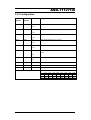
3.4 Menu organization
The architecture of the menus is built around main menus and secondary menus. Display
disappears after one minute and will reappear by pressing any of push-button
Level 1
Level 2
ASD-712 i
only
Level 3 Values
LVL
è
è
I-1&2
è
è
L&R
è
è
I-1
è
è
L
è
è
-
96; … ;0; … 31.
è
I-2
è
è
R
è
0.5 dB
steps
DITH
è
è
I-1&2
è
è
I-1
è
è
è
OFF; 20bt; 18bt; 16bt
è
I-2
è
MUTE
è
è
O-1&2
è
è
L&R
è
è
O-1
è
è
L
è
è
OFF; ON
è
O-2
è
è
R
è
TEST
è
è
I-1&2
è
è
I-1
è
è
è
OFF; EBU
è
I-2
è
REF
è
è
è
INT
è
EXT,PAL,NTSC,WORD,AES
FREQ
è
è
è
32K; 44K1; 48K; 96K
AES
è
è
O-1&2
è
è
O-1
è
è
MODE
è
è
PRO; CONS
è
O-2
è
ORIG
è
è
O-1&2
è
è
CHR1
è
è
O-1
è
è
CHR2
è
è
0000
4 x 1 of 96 ASCII
characters
è
O-2
è
è
CHR3
è
è
CHR4
è
DEST
è
è
O-1&2
è
è
CHR1
è
è
O-1
è
è
CHR2
è
è
0000
4 x 1 of 96 ASCII
characters
è
O-2
è
è
CHR3
è
è
CHR4
è
ALRM
è
è
I-1&2
è
è
I-1
è
è
è
OFF; ON
è
I-2
è
FACT
è
è
è
NO; YES

ASDASD--711i/712i711i/712i
18
3.5 Menu LVL
This menu enables to select input level configuration. This adjustment is made within a range of
-96 dB to +31.5 dB by 0.5 dB steps.
Procedure
• Press [ + ] or [ - ] displays the LVL menu,
• Press [ SEL ] displays the selected input, use [ + ] or [ - ] to scroll through the available audio
inputs. (ASD-712i only)
• Press [ SEL ] validates the input and displays the selected channel , use [ + ] or [ - ] to scroll
through the available audio channels.
• Press on [ SEL ] validates the channel and displays the current level value. Use [ + ] to
increase or [ - ] to decrease the value. For a quicker response, keep the push button
depressed.
• Press [ SEL ] to store the new parameter, and to return to the previous menu
• Or press [ ESC ] to return to the previous menu without updating the parameter.
• To turn off the display, press [ ESC ].
3.6 Menu DITH
Follow these steps for Dither insertion (Output Word Length) configuration.
Procedure
• Press [ + ] or [ - ] displays the DITH menu,
• Press [ SEL ] displays the selected channel, use [ + ] or [ - ] to scroll through the available
audio channels. (ASD-712i only)
• Press [ SEL ] validates the channel and displays the current value , use [ + ] or [ - ] to scroll
through the available values.
• Press [ SEL ] to store the new parameter, and to return to the previous menu
• Or press [ ESC ] to return to the previous menu without updating the parameter.
• To turn off the display, press [ ESC ].
3.7 Menu MUTE
Follow these steps to disable or enable mute functions.
Procedure
• Press [ + ] or [ - ] displays the MUTE menu,
• Press [ SEL ] displays the selected channel, use [ + ] or [ - ] to scroll through the available
audio channels. (ASD-712i only)
• Press [ SEL ] validates the channel and displays the current value , use [ + ] or [ - ] to scroll
through the available values ON and OFF.
• Press [ SEL ] to store the new parameter, and to return to the previous menu
• Or press [ ESC ] to return to the previous menu without updating the parameter.
• To turn off the display, press [ ESC ].

ASDASD--711i/712i711i/712i
19
3.8 Menu TEST
An internal tone generator provides a steady - 18 dBFS 1 kHz continuous sine wave on right
channel and a pulsed steady - 18 dBFS 1 kHz continuous sine wave on left channel. To enable
the tone generator, follow these steps
Procedure
• Press [ + ] or [ - ] displays the TEST menu,
• Press [ SEL ] displays the selected channel, use [ + ] or [ - ] to scroll through the available
audio channels. (ASD-712i only)
• Press [ SEL ] validates the channel and displays the current value , use [ + ] or [ - ] to scroll
through the available values OFF and EBU.
• Press [ SEL ] to store the new parameter, and to return to the previous menu
• Or press [ ESC ] to return to the previous menu without updating the parameter.
• To turn off the display, press [ ESC ].
3.9 Menu REF
This menu enables to select the sync mode, internal or external.
Procedure
• Press [ + ] or [ - ] displays the REF menu,
• Press [ SEL ] displays current value, use [ + ] or [ - ] to scroll through the available values INT
or EXT. When external reference is valid the display indicates AES, WORD, PAL or NTSC.
• Press [ SEL ] to store the new parameter, and to return to the previous menu
• Or press [ ESC ] to return to the previous menu without updating the parameter.
• To turn off the display, press [ ESC ].

ASDASD--711i/712i711i/712i
20
3.10 Menu FREQ
To set the sampling frequency, follow these steps.
Procedure
• Press [ + ] or [ - ] displays the FREQ menu,
• Press [ SEL ] displays the selected value, use [ + ] or [ - ] to scroll through the available
frequency values (32k, 44k1, 48k et 96k).
• Press [ SEL ] to store the new parameter, and to return to the previous menu
• Or press [ ESC ] to return to the previous menu without updating the parameter.
• To turn off the display, press [ ESC ].
3.11 Menu AES
This menu is used to insert channel status information in AES outputs. Consumer or professional
mode can be selected. In consumer mode sample rate, and in professional mode lock sample
rate, word length, origin and destination parameters follow the user selection.
Procedure
• Press [ + ] or [ - ] displays the AES menu,
• Press [ SEL ] displays selected channel, use[ + ] or [ - ] to scroll through the available
Channels. (ASD-712i only)
• Press [ SEL ]validates the channel and displays the mode, use [ + ] or [ - ] to select the mode
PRO (PROfessional) or CONS (CONSumer)
• Press [ SEL ] to store the new parameter, and to return to the previous menu
• Or press [ ESC ] to return to the previous menu without updating the parameter.
• To turn off the display, press [ ESC ].
La page charge ...
La page charge ...
La page charge ...
La page charge ...
La page charge ...
La page charge ...
La page charge ...
La page charge ...
La page charge ...
La page charge ...
La page charge ...
La page charge ...
La page charge ...
La page charge ...
La page charge ...
La page charge ...
La page charge ...
La page charge ...
La page charge ...
La page charge ...
La page charge ...
La page charge ...
La page charge ...
-
 1
1
-
 2
2
-
 3
3
-
 4
4
-
 5
5
-
 6
6
-
 7
7
-
 8
8
-
 9
9
-
 10
10
-
 11
11
-
 12
12
-
 13
13
-
 14
14
-
 15
15
-
 16
16
-
 17
17
-
 18
18
-
 19
19
-
 20
20
-
 21
21
-
 22
22
-
 23
23
-
 24
24
-
 25
25
-
 26
26
-
 27
27
-
 28
28
-
 29
29
-
 30
30
-
 31
31
-
 32
32
-
 33
33
-
 34
34
-
 35
35
-
 36
36
-
 37
37
-
 38
38
-
 39
39
-
 40
40
-
 41
41
-
 42
42
-
 43
43


Miranda ASD-712i Manual To Installation And Operation
- Taper
- Manual To Installation And Operation
- Ce manuel convient également à
dans d''autres langues
- English: Miranda ASD-712i
Documents connexes
Autres documents
-
Baumer MY-COM A75/80 Fiche technique
-
 ASD ASD-SFL2040 Manuel utilisateur
-
JVC SP-A110 Manuel utilisateur
-
TC Electronic BMC-2 Le manuel du propriétaire
-
Denon AVR-1611 Manuel utilisateur
-
Denon AVR-391E3 Le manuel du propriétaire
-
MSI FUZION Le manuel du propriétaire
-
-
-
