
1-877-SKIL-999
OR
www.skil.com
WARNING: To reduce the risk of injury, the user must read and understand the
Operator’s Manual before using this product. Save these instructions for future reference.
AVERTISSEMENT : Afin de réduire les risques de blessure, l’utilisateur doit lire et
comprendre le guide d’utilisation avant d’utiliser cet article. Conservez le présent guide
afin de pouvoir le consulter ultérieurement.
ADVERTENCIA : Para reducir el riesgo de lesiones, el usuario debe leer y comprender
el Manual del operador antes de utilizar este producto. Guarde estas instrucciones para
consultarlas en caso sea necesario.
Owner’s Manual
Guide d’utilisation
Manual del propietario
For Customer Service
Pour le service à la clientèle
Servicio al cliente
Model/ Modelo/ Modèle: #LL932301/LL932401
Compact Self-Leveling Cross Line Laser
Compact À Rayon Laser En Croix Et À
Nivellement Automatique
Láser Autonivelante Compacto
De Líneas Cruzadas

2
TABLE OF CONTENTS
General Laser Tool Safety Warnings .................3-4
FCC Statement ...................................4-5
Safety Rules For Connecting Power Supply ...........5-6
Symbols ........................................7-9
Get to Know Your Laser Tool ........................10
Packing List ......................................11
Specications ....................................11
Operating Instructions ..........................12-17
Maintenance ......................................18
Trouble Shooting ..................................19
Limited Warranty Of Skil Consumer Tools ..........20-21

3
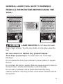
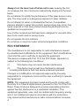
GENERAL LASER TOOL SAFETY WARNINGS
READ ALL INSTRUCTIONS BEFORE USING THE
TOOL!
4.44 Wh
CAN ICES-3(B)/NMB-3(B)
MADE IN CHINA / HECHO EN CHINA
FABRIQUÉ EN CHINE
SERIAL NO.
SERIE NO.
NUMÉRO DE SÉRIE
Model / Modelo / Modèle: LL932401
520nm, OUTPUT < 1mW/CLASS II LASER PRODUCT
3.7V 1200mAh Li-Polymer
COMPLIES WITH 21 CFR PARTS 1040.10 AND 1040.11
PRODUCTO LÁSER CON SALIDA < 1mW. CLASE II,
520 nm, 3,7V 1200mAh polímero de litio
CUMPLE CON LAS SECCIONES 21 CFR 1040.10 Y 1040.11
520 nm, SORTIE < 1 mW/PRODUIT LASER DE CLASSE II
Pile au lithium-polymère de 3,7 V, 1200 mAh
CONFORME AUX NORMES 21CFR ARTICLES 1040.10
ET 1040.11
LASER RADIATION-DO NOT STARE INTO BEAM
RADIACIÓN LÁSER: NO MIRE DIRECTAMENTE EL RAYO
RAYONNEMENT LASER – NE FIXEZ PAS DES YEUX LE
RAYON LASER
CAUTION: Risk of re and burns. Do not open, crush, heat
above 100° C (212° F) or incinerate.
PRECAUCIÓN : Riesgo de incendio y quemaduras. No abra,
triture, permita que esté a mayor temperatura que 100° C
(212 °F) ni incinere.
ATTENTION : Risque d’incendie et de brûlures. N’ouvrez pas
le produit, ne l’écrasez pas, ne le chauffez pas à plus de
100ºC (212°F) et ne l’incinérez pas.
CAUTION/PRECAUCIÓN/ATTENTION
AVOID EXPOSURE/EVITE LA
EXPOSICIÓN/ÉVITEZ
L’EXPOSITION
LASER RADIATION IS EMITTED
FROM THIS APERTURE
LA RADIACIÓN LÁSER SE EMITE
DE ESTA ABERTURA
CET OUTIL PRODUIT UN
RAYONNEMENT LASER
4.44 Wh
CAN ICES-3(B)/NMB-3(B)
MADE IN CHINA / HECHO EN CHINA
FABRIQUÉ EN CHINE
SERIAL NO.
SERIE NO.
NUMÉRO DE SÉRIE
Model / Modelo / Modèle: LL932301
635nm, OUTPUT < 1mW/CLASS II LASER PRODUCT
3.7V 1200mAh Li-Polymer
COMPLIES WITH 21 CFR PARTS 1040.10 AND 1040.11
PRODUCTO LÁSER CON SALIDA < 1mW. CLASE II,
635 nm, 3,7V 1200mAh polímero de litio
CUMPLE CON LAS SECCIONES 21 CFR 1040.10 Y 1040.11
635 nm, SORTIE < 1 mW/PRODUIT LASER DE CLASSE II
Pile au lithium-polymère de 3,7 V, 1200 mAh
CONFORME AUX NORMES 21CFR ARTICLES 1040.10
ET 1040.11
LASER RADIATION-DO NOT STARE INTO BEAM
RADIACIÓN LÁSER: NO MIRE DIRECTAMENTE EL RAYO
RAYONNEMENT LASER – NE FIXEZ PAS DES YEUX LE
RAYON LASER
CAUTION: Risk of re and burns. Do not open, crush, heat
above 100° C (212° F) or incinerate.
PRECAUCIÓN : Riesgo de incendio y quemaduras. No abra,
triture, permita que esté a mayor temperatura que 100° C
(212 °F) ni incinere.
ATTENTION : Risque d’incendie et de brûlures. N’ouvrez pas
le produit, ne l’écrasez pas, ne le chauffez pas à plus de
100ºC (212°F) et ne l’incinérez pas.
CAUTION/PRECAUCIÓN/ATTENTION
WARNING
LASER RADIATION.
Do not stare into beam.
Class II laser product. Turn the laser beam on only when using this
tool.
Do not remove or deface any product labels.
Avoid direct eye exposure.
The laser beam can cause ash
blindness.
Do not operate the tool around children or allow children to operate
the tool.
Do not
place the tool in a position that may cause anyone to stare at
the laser beam, whether intentionally or unintentionally.
Do not use on surfaces such as sheet steel that have shiny,
reective surfaces. The shiny surface could reect the beam back at
the operator.

4
Always turn the laser tool off when not in use.
Leaving the tool
on increases the risk of someone inadvertently staring into the laser
beam.
Do not attempt to modify the performance of this laser device in any
way. This may result in a dangerous exposure to laser radiation.
Do not attempt to repair or disassemble the tool. If unqualied
persons attempt to repair this product, serious injury may occur. Any
repair required on this laser product should be performed only by
qualied service personnel.
Use of other accessories that have been designed for use with other
laser tools could result in serious injury.
Do not operate the tool outdoors.
Do not place or store tool under extreme temperature conditions.
FCC STATEMENT
The manufacturer is not responsible for radio interference caused
by unauthorized modications to this equipment. Such modications
could void the user’s authority to operate the equipment.
This device complies with Part 15 of the FCC Rules. Operation is
subject to the following two conditions:
(1) This device may not cause harmful interference.
(2) This device must accept any interference received,
including interference that may cause undesired operation.
Changes or modications not expressly approved by the party
responsible for compliance could void the user’s authority to operate
the equipment.
NOTE:
This equipment has been tested and found to comply with
the limits for a Class B digital device, pursuant to Part 15 of the FCC
Rules. These limits are designed to provide reasonable protection
against harmful interference in a residential installation. This
equipment generates, uses, and can radiate radio frequency energy
and, if not installed and used in accordance with the instructions,
may cause harmful interference to radio communications. However,

5
there is no guarantee that interference will not occur in a particular
installation. If this equipment does cause harmful interference to
radio or television reception, which can be determined by turning
the equipment off and on, the user is encouraged to try to correct
the interference by one or more of the following measures:
•
Reorient or relocate the receiving antenna.
•
Increase the separation between the equipment and receiver.
•
Connect the equipment into an outlet on a circuit different from
that to which the receiver is connected.
•
Consult the dealer or an experienced radio/TV technician for help.
DANGER
People with electronic devices, such as
pacemakers, should consult their physician(s)
before using this product. Operation of electrical equipment in close
proximity to a heart pacemaker could cause interference or failure
of the pacemaker.
SAFETY RULES FOR CONNECTING POWER
SUPPLY
WARNING
Read and follow all instructions below
before connecting with an external power
supply, such as AC supply or DC mobile power.
Failure to follow
all instructions below may result in electric shock, explosion, re
and/or serious personal injury.
Use only an adapter for which output voltage is 5V and output
electricity is ≥0.5A.
Conrm that the adapter suits the AC supply before connecting.
Conrm that the mobile power source has output voltage of 5V and
output electricity of ≥0.5A before connecting.
Keep the adapter clean. Check the adapter, cable and plug before
do connecting. If damage is detected, do not use or repair by
yourself, change the damaged one or get repairs performed by
authorized service personnel, otherwise electric shock may occur.

6
Do not connect with AC supply on easily ammable surfaces (e.g.,
paper, textiles, etc.) or surroundings. The heating of the adapter
during use may pose a re hazard.
Children or persons with physical, sensory or mental limitations
or lack of experience and knowledge are not capable of securely
operating the adapter unless they are being given supervision or
have been instructed by a responsible person.

7
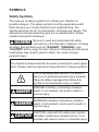
SYMBOLS
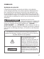
Safety Symbols
The purpose of safety symbols is to attract your attention to
possible dangers. The safety symbols and the explanations with
them deserve your careful attention and understanding. The
symbol warnings do not, by themselves, eliminate any danger. The
instructions and warnings they give are no substitutes for proper
accident prevention measures.
WARNING
Be sure to read and understand all safety
instructions in this Operator’s Manual, including
all safety alert symbols such as “
DANGER
,” “
WARNING
,” and
“
CAUTION
” before using this tool. Failure to following all instructions
listed below may result in electric shock, re, and/or serious
personal injury.
The denitions below describe the level of severity for each signal
word. Please read the manual and pay attention to these symbols.
This is the safety alert symbol. It is used to
alert you to potential personal injury hazards.
Obey all safety messages that follow this
symbol to avoid possible injury or death.
DANGER
DANGER indicates a hazardous situation
which, if not avoided, will result in death or
serious injury.
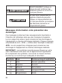
WARNING
WARNING indicates a hazardous situation
which, if not avoided, could result in death or
serious injury.
CAUTION
CAUTION, used with the safety alert symbol,
indicates a hazardous situation which, if not
avoided, will result in minor or moderate injury.

8
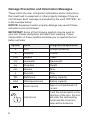
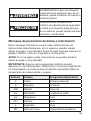
Damage Prevention and Information Messages
These inform the user of important information and/or instructions
that could lead to equipment or other property damage if they are
not followed. Each message is preceded by the word “NOTICE”, as
in the example below:
NOTICE:
Equipment and/or property damage may result if these
instructions are not followed.
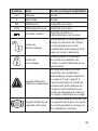
IMPORTANT:
Some of the following symbols may be used on
your tool. Please study them and learn their meaning. Proper
interpretation of these symbols will allow you to operate the tool
better and safer.
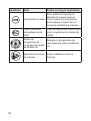
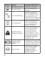
Symbol Name Designation/Explanation
V Volts Voltage (potential)
A Amperes Current
mW Milliwatt Power
nm nanometer Wavelength
kg Kilograms Weight
min Minutes Time
s Seconds Time
Wh Watt-hours Battery capacity
mAh Milliampere-Hours Battery capacity
Direct current
Type or a characteristic of
current
Unlock Icon
Push the mode switch in the
direction of the icon, the tool
will enter the self-leveling
mode and the cross line
laser will be turned on

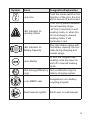
9
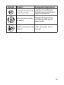
Symbol Name Designation/Explanation
Lock Icon
Push the mode switch in the
direction of the icon, the tool
will be turned off and locked
LED Indicator for
Leveling Status
If the tool is placed exceeds
the self-leveling range
(±4°from horizontal) in self-
leveling mode, or when the
tool is working in manual
leveling mode, it will
illuminate in red.
LED Indicator for
Battery Capacity
The color status varies with
the battery capacity the tool
rests during charging and
normal usage
Laser Button
To turn the compact self-
leveling cross line laser on
and off in manual leveling
mode
CEC Energy Efciency
Logo
CEC certication logo for
battery charging system
Li-ion RBRC seal
Designates Li-ion battery
recycling program
Read manual symbol Alerts user to read manual

10
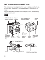
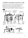
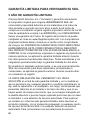
GET TO KNOW YOUR LASER TOOL
This compact self-leveling cross line laser is highly versatile. It can
be hand-held, leveled on a horizontal surface or mounted on the
clamp.
Use the automatic cross line laser for aligning: tiles, wall studding,
windows, doors, etc.
Fig. 1
LED Indicator for
Battery Capacity
Laser
Button
1/4”
Threaded
Mounting
Hole on
Bottom
1/4”
Threaded
Mounting
Hole on
Top
Handle
USB Charging Cable
Rod
Lock
Icon
Micro USB
Charging
Port
1/4" Screw Platform
Laser
Aperture
Mode
Switch
Unlock
Icon
LED Indicator for
Leveling Status
Knob

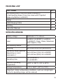
11
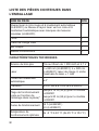
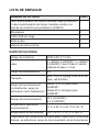
PACKING LIST
PART NAME QTY
Self-leveling Red Cross line Laser (LL932301),
or Self-leveling Green Cross line Laser with Projected
Measuring Marks (LL932401)
1
Clamp 1
USB Charging Cable 1
Soft Bag 1
Instruction Manual 1
SPECIFICATIONS
Battery voltage 1200mAh 3.7 V Lithium
Laser
λ=635nm (LL932301); λ=520nm
(LL932401); Class II laser; Maximum
laser output < 1mw
Self-levelling Range ± 4°
Accuracy ±3/16 inch at 30 foot (±0.5mm/m)
Operating range (typically,
depending on room
illumination )*
Up to 50 feet (15m) for LL932301
Up to 65 feet (20m) for LL932401
Operating time
16h (LL932301)
6h (LL932401)
Optimum operating
temperature
+23°F to 104°F (-5
o
C to 40
o
C)
Storage temperature -4°F to 158°F (-20
o
C to 70
o
C)
*Important: Under unfavorable conditions, such as in bright light,
the tool’s operating range will be reduced.

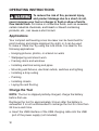
12
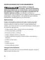
OPERATING INSTRUCTIONS
WARNING
To reduce the risk of re, personal injury,
and product damage due to a short circuit,
never immerse your tool or charger in uid or allow a uid to
ow inside them.
Corrosive or conductive uids, such as seawater,
certain industrial chemicals, and bleach or bleach containing
products, etc., can cause a short circuit.
Applications
Your compact self-leveling cross line laser can be hand-held for
point marking and simple alignment by sight, or it can be used
to make a “chalk line” by using the lock mode. It is ideal for the
following applications:
•
Hanging pictures, photos, or artwork on walls
•
Wallpapering and stencil work
•
Framing doors and windows
•
Installing electrical wiring and pipes
•
Mounting wall xtures, electrical outlets, switches and lighting
•
Installing a drop ceiling
•
Painting
•
Installing closets
•
Laying tile and ooring
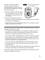
Charge the Tool
NOTE:
The tool is shipped partially charged; charge the battery
before rst use.
Recharge the tool for approximately 3 hours after the battery is
exhausted. It is not recommended to recharge the tool for more than
24 hours each time.
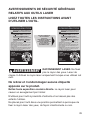
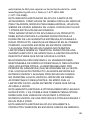
a. Insert the USB interface of the USB charging cable into the USB
port of the power supply (not included).

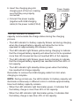
13
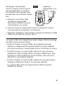
b. Insert the charging plug into
charging port of the tool, making
sure that they are properly
connected.
c. Connect the power supply
(together with USB charging
cable) to the power outlet (FIG.2)
The LED indicator for battery
capacity communicate the charge status during the charging
process.
•
The LED indicator for battery capacity ickers red during charging
when the charged battery capacity will allow the tool to be
operated for approximately 30 minutes or less.
•
The LED indicator light ickers yellow during charging to indicate
that the charged battery capacity will allow the tool to be operated
more than 30 minutes but has not reached 90% of full capacity.
•
The LED indicator light ickers green during charging to indicate
that the charged battery capacity has reached more than 90% of
full capacity.
•
The LED indicator light steadily shines green when the battery
has reached full charge capacity.
Remember to remove the USB charging cable from tool when
charging is complete.
NOTE:
During normal use, the LED indicator for battery capacity will
illuminate continuously in different colors to indicate approximately
how much battery capacity remains.
•
When the LED indicator light illuminates green, it indicates that
the battery charge is more than 40% of full capacity.
•
When the LED indicator light illuminates yellow, it indicates that
the battery charge is less than 40% of full capacity
Fig. 2
Power Supply
(not included)

14
•
When the LED indicator light illuminates red, it indicates that the
tool can only be operated for approximately 30 minutes before
turning off automatically.
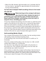
To Turn the Compact Self-Leveling Cross Line Laser
On and Off
WARNING
When turning on the compact self-level-
ing cross line laser, always be aware of
protecting your eyes and the eyes of those around you.
Never point the compact self-leveling cross line laser at
anyone’s face, including your own.
To turn the compact self-leveling cross line laser on, push the mode
switch in the direction of the unlock icon, or press the laser button
when the mode switch is already in the direction of the lock icon.
If the cross line laser is turned on by the mode switch in the direction of
the unlock icon, push the mode switch in the direction of the lock icon
to turn off. If the cross line laser is turned on with the mode switch in the
direction of the lock icon, press the laser button again to turn off.
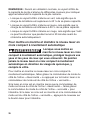
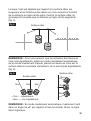
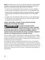
Self-Leveling Mode (Fig.3)
Your compact self-leveling cross line laser has two working modes:
self-leveling mode and manual leveling mode.
In self-leveling mode, the tool will level itself if it is within ±4° of
horizontal.
Place the compact self-leveling cross line laser on a at, smooth
surface that is within ±4° of horizontal.
Turn the tool on by sliding the mode switch in the direction of
the unlock icon. The compact self-leveling cross line laser will
automatically level within 6 seconds.
If the surface on which the compact self-leveling cross line laser is
placed exceeds ±4° from horizontal, the laser line will blink as an
alarm and the LED indicator for leveling status will illuminate in red.
In this event, adjust the angle of the surface slightly.

15
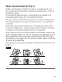
To turn off the laser lines, slide the mode switch in the direction of
the lock icon.
Fig. 3
Manual Leveling Mode
Keep the mode switch in the lock icon position and press the laser
button to turn on the laser. The laser lines are now locked and are
no longer self-leveling.
NOTE:
In this mode, the LED indicator for leveling status will always
illuminate in red; the laser lines are projected continuously and will
not blink, even if the slope angle exceeds 4°.
Press the laser button again to turn off the laser.
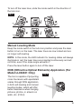
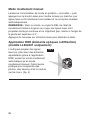
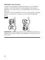
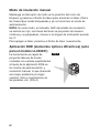
DOE (Diffractive Optical Elements) Application (For
Model LL932401 Only)
The tool is capable of projecting
cross line lasers with equidistant
scales through DOE application
in both self-leveling and manual
leveling modes, which will offer
better assistance when hanging
pictures, photos, or artwork on
walls, etc. (FIG.4)
Fig. 4

16
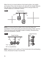
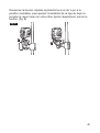
When the tool is moved relative to the target surface, the lengths
and scales of the cross line lasers will vary with the straight distance
from the tool to the target surface and will be enlarged when the
straight distance is increased. (FIG.5)
Fig. 5
Target Surface
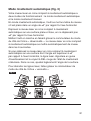
NOTE:
To ensure that the scales of the cross line lasers are
equidistant in both self-leveling and manual leveling modes, aim the
cross line lasers onto the target surface vertically; otherwise they
will not be equidistant. (FIG.6)
Fig. 6
Target Surface
Target Surface
No
No NoYes
“Yes”- equidistantly
“No”-un-equidistantly
Yes
No
NOTE:
Keep the tool to within ±4° from horizontal in the self-leveling
mode, otherwise the laser line will blink.

17
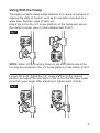
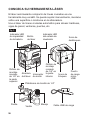
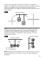
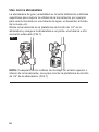
Using With the Clamp
The highly versatile clamp easily attaches to a variety of surfaces to
improve the utility of the tool, such as for use when mounted on a
water pipe, banister, edge of table, etc.
Mount the tool to the 1/4” screw platform on the clamp and secure
the clamp to a pole, pipe or other suitable item (FIG.7).
Fig. 7
NOTE:
Either of the mounting holes on top and bottom side of the
tool may be mounted to the 1/4” screw platform of the clamp. (FIG.7)
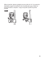
Loosen the knob. Adjust the 1/4” screw platform to the desired
position and adjust the orientation of the rod so that the laser beam
projects to your target. After adjustment, tighten knob. (FIG.8)
Fig. 8

18
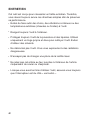
MAINTENANCE
This tool has been designed to be a low-maintenance tool.
However, in order to maintain its performance, you must always
follow these simple directions:
•
Avoid exposing the tool to shock, continuous vibration or extreme
hot or cold temperature.
•
Always store the tool indoors.
•
Always keep the tool free of dust and liquids. Use only a clean,
soft cloth for cleaning. Avoid using any solvents.
•
Do not disassemble the tool; this will expose the user to
hazardous radiation exposure.
•
Do not attempt to change any part of the laser lens.
•
Do not dispose of this product in re, batteries inside the product
may explode or leak.
•
After you have nished using the tool, always make sure that the
switch is in the lock icon position.

19
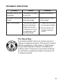
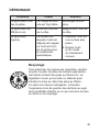
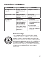
TROUBLE SHOOTING
Problem Cause Remedy
The laser line is not
projected.
The battery charge
is too low.
Charge the battery.
The laser line is hard
to see.
The tool is too far
from the target.
Move the tool closer
to the target.
Laser line ickers. The surface where
the tool has been
placed is uneven
or the tool is out of
its automatic self-
leveling range.
1. Place the tool on a
more level surface.
2. Set the tool to its
manual leveling
mode.
For Recycling
To preserve natural resources, please recycle or
dispose of batteries properly. This product contains
lithium-ion batteries. Local, state, or federal laws
may prohibit disposal of lithium-ion batteries in
ordinary trash. Consult your local waste authority
for information regarding available recycling and/
or disposal options.

20
LIMITED WARRANTY OF SKIL CONSUMER TOOLS
5 YEAR LIMITED WARRANTY- LEGAL
Chervon North America, Inc. ("Seller") warrants to the original
purchaser only, that all SKIL consumer TOOLS will be free from
defects in material or workmanship for a period of ve years
from date of purchase, if original purchaser registers the product
within 30 days from purchase. BATTERIES AND CHARGERS are
warranted for 2 years. Product registration can be completed online
at www.Registermyskil.com. Original purchasers should also retain
their receipt as proof of purchase. THE FIVE-YEAR WARRANTY
PERIOD FOR TOOLS IS CONDITIONED ON REGISTRATION
OF THE PRODUCT WITHIN 30 DAYS OF PURCHASE. If original
purchasers do not register their product timely, the foregoing
limited warranty will apply for a duration of three years for tools.
All batteries and chargers will remain under the two-year limited
warranty.
Notwithstanding the foregoing, if a SKIL consumer tool is used
for industrial, professional or commercial purposes, the foregoing
warranty will apply for a duration of ninety days, regardless of
registration.
SELLER’S SOLE OBLIGATION AND YOUR EXCLUSIVE REMEDY
under this Limited Warranty and, to the extent permitted by law, any
warranty or condition implied by law, shall be the repair or
replacement of parts, without charge, which are defective in material
or workmanship and which have not been misused, carelessly
handled, or repaired by persons other than Seller or Authorized
Service Station. To make a claim under this Limited Warranty, you
must return the complete product, transportation prepaid, to any
SKIL Factory Service Center or Authorized Service Station. For
Authorized SKIL Power Tool Service Stations, please visit www.
Registermyskil.com or call 1-877-SKIL-999 (1-877-754-5999).
THIS LIMITED WARRANTY DOES NOT APPLY TO ACCESSORY
ITEMS SUCH AS CIRCULAR SAW BLADES, DRILL BITS,
ROUTER BITS, JIGSAW BLADES, SANDING BELTS, GRINDING
WHEELS AND OTHER RELATED ITEMS.
La page charge ...
La page charge ...
La page charge ...
La page charge ...
La page charge ...
La page charge ...
La page charge ...
La page charge ...
La page charge ...
La page charge ...
La page charge ...
La page charge ...
La page charge ...
La page charge ...
La page charge ...
La page charge ...
La page charge ...
La page charge ...
La page charge ...
La page charge ...
La page charge ...
La page charge ...
La page charge ...
La page charge ...
La page charge ...
La page charge ...
La page charge ...
La page charge ...
La page charge ...
La page charge ...
La page charge ...
La page charge ...
La page charge ...
La page charge ...
La page charge ...
La page charge ...
La page charge ...
La page charge ...
La page charge ...
La page charge ...
La page charge ...
La page charge ...
La page charge ...
La page charge ...
La page charge ...
La page charge ...
La page charge ...
La page charge ...
La page charge ...
La page charge ...
La page charge ...
La page charge ...
-
 1
1
-
 2
2
-
 3
3
-
 4
4
-
 5
5
-
 6
6
-
 7
7
-
 8
8
-
 9
9
-
 10
10
-
 11
11
-
 12
12
-
 13
13
-
 14
14
-
 15
15
-
 16
16
-
 17
17
-
 18
18
-
 19
19
-
 20
20
-
 21
21
-
 22
22
-
 23
23
-
 24
24
-
 25
25
-
 26
26
-
 27
27
-
 28
28
-
 29
29
-
 30
30
-
 31
31
-
 32
32
-
 33
33
-
 34
34
-
 35
35
-
 36
36
-
 37
37
-
 38
38
-
 39
39
-
 40
40
-
 41
41
-
 42
42
-
 43
43
-
 44
44
-
 45
45
-
 46
46
-
 47
47
-
 48
48
-
 49
49
-
 50
50
-
 51
51
-
 52
52
-
 53
53
-
 54
54
-
 55
55
-
 56
56
-
 57
57
-
 58
58
-
 59
59
-
 60
60
-
 61
61
-
 62
62
-
 63
63
-
 64
64
-
 65
65
-
 66
66
-
 67
67
-
 68
68
-
 69
69
-
 70
70
-
 71
71
-
 72
72


Skil LL932401 Le manuel du propriétaire
- Taper
- Le manuel du propriétaire
- Ce manuel convient également à
dans d''autres langues
- English: Skil LL932401 Owner's manual
- español: Skil LL932401 El manual del propietario
